
Subscribe to Our Youtube Channel
Related Manuals for Muller Elektronik MIDI 3.0


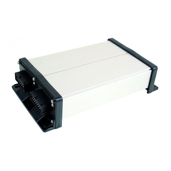
Summary of Contents for Muller Elektronik MIDI 3.0
- Page 1 Operating Instructions SPRAYER-Controller MAXI and MIDI 3.0 Version: V1.20180921 30303187-02-EN Read and follow these operating instructions. Keep these operating instructions in a safe place for later reference.
- Page 2 Company details Document Operating Instructions Product: SPRAYER-Controller MAXI and MIDI 3.0 Document number: 30303187-02-EN As of software version: 07.07.14 Original language: German Copyright © Müller-Elektronik GmbH & Co.KG Franz-Kleine-Straße 18 33154 Salzkotten Germany Phone: ++49 (0) 5258 / 9834 - 0 Fax: ++49 (0) 5258 / 9834 - 90 Email: info@mueller-elektronik.de...
-
Page 3: Table Of Contents
Table of contents Table of contents For your safety Basic safety instructions Intended use Layout and meaning of warnings Layout and meaning of alert messages User requirements Safety sign for the field sprayer Safety stickers on the product Disposal EU declaration of conformity About these Operating Instructions Who should read these instructions Diagrams in this manual... - Page 4 Table of contents 5.2.1 Spray data area 5.2.2 Boom display area 5.2.3 Icons beside the implement image 5.2.4 Icons on the implement image Control units Operating job computer on the field Tank filling 6.1.1 Filling up the tank manually without additional systems 6.1.2 Filling up the tank with TANK-Control 6.1.3...
- Page 5 Table of contents 7.1.10 “Tank Size” parameter 7.1.11 “Tank level alarm” parameter 7.1.12 “Impulses Main Flow” parameter 7.1.13 “Stirring off Below” parameter 7.1.14 “Maximum Wind Speed” parameter 7.1.15 “Extremity nozzles set” parameter 7.1.16 “Pump” parameter 7.1.17 “Section Control” parameter 7.1.18 “Filling Mode”...
- Page 6 Table of contents Troubleshooting Alarm messages Checking the software version Technical specifications ECU-MIDI 3.0 job computer ECU-MAXI 3.0 job computer Available languages V1.20180921 30303187-02-EN...
-
Page 7: For Your Safety
For your safety Basic safety instructions For your safety Basic safety instructions Operation Be sure to always comply with the following instructions during operation: ▪ Before you leave the vehicle cab, ensure that all automatic mechanisms are deactivated or manual mode is activated. ▪... -
Page 8: Layout And Meaning Of Warnings
For your safety Layout and meaning of warnings All applicable accident prevention regulations and all other generally recognized safety, industrial, and medical standards as well as all road traffic laws must be observed. Any unauthorized modifications made to the equipment will void the manufacturer's warranty. Layout and meaning of warnings All safety instructions found in these Operating Instructions are composed in accordance with the following pattern:... -
Page 9: User Requirements
For your safety User requirements Alarm message structure Type of alarm Name of the component that caused the alarm. Problem description and solution Information on the exact cause of an alarm message or how to rectify a fault can be found in the section “Alarm messages”... -
Page 10: Safety Stickers On The Product
For your safety Safety stickers on the product Safety sign Where to attach Meaning Near the the bend area between tractor Do not stay in the bend area and trailed implement. during operation. Safety stickers on the product Sticker on the job computer Do not clean with a high-pressure cleaner. -
Page 11: Eu Declaration Of Conformity
ME_RE ECU-MAXI 3.0 Item number: 30303185 Variants: 30303187 Harmonised standards applied: EN ISO 14982:2009 (EMC Directive 2014/30/EU) Product name: ME_RE ECU-MIDI 3.0 Item number: 30303184 Variants: 3004748207, 3004748208, 3004748209, 3004748210, 3004765002, 30193549, 3019354901, 3019354902, 3019354903, 3019354904, 3019354905, 3019354906, 3019354907, 3019354908, 3019354909,... -
Page 12: About These Operating Instructions
Who should read these instructions These operating instructions are intended for operators of field sprayers that are equipped with the SPRAYER-Controller MAXI 3.0 or MIDI 3.0 system with the standard configuration. The instructions will show you: ▪ The meaning of the icons on the screen;... -
Page 13: Layout Of Operating Instructions
About these Operating Instructions Layout of operating instructions Layout of operating instructions The operating instructions explain step by step how you can perform certain operations with the product. We use the following symbols throughout these Operating Instructions to identify different operating instructions: Type of depiction Meaning... -
Page 14: About The Job Computer
About the job computer Job computer functions The SPRAYER-Controller MIDI 3.0 and MAXI 3.0 job computers are ISOBUS job computers that can control the operation of field sprayers. The ISOBUS job computer is the control central of the sprayer. Several sensors are connected to the job computer, which monitor important implement parts. -
Page 15: Main System - Maxi
About the job computer System Overview Example: MIDI 3.0 as the main job computer 3.2.1 Main system - MAXI The system can be expanded. In the basic version, it consists of a job computer that is connected to the junction box and the ISOBUS power socket of the tractor. -
Page 16: Main System - Midi
The system can be expanded. The basic version consists of one to three job computers. The first job computer is connected to the ISOBUS power socket on the tractor. Main system of the MIDI 3.0 version Connector cable for job computer to ISOBUS... -
Page 17: Extension: Distance-Control Ii
About the job computer System Overview 3.2.3 Extension: DISTANCE-Control II DISTANCE-Control II Connection to ECU-MAXI 3.0 or to the last Junction box ECU-MIDI job computer. Termination plug. Job computer Otherwise, connection of other extensions. The instructions for the DISTANCE-Control II extension can be found in the download area of our website: www.mueller-elektronik.de 3.2.4... -
Page 18: Extension: Eds
About the job computer Software extensions Connection to the main system or to a system Junction box add-on Job computer TANK-Control III on-board integrated display/controller Water and dust protection cap or terminating Fill level sensor resistor. Otherwise, connection of extensions The instructions for the TANK-Control III extension can be found in the download area of our website: www.mueller-elektronik.de 3.2.5... -
Page 19: Rating Plate
About the job computer Rating plate Rating plate Abbreviations on the rating plate Abbreviation Meaning Customer number If the product was manufactured for an agricultural machinery manufacturer, the agricultural machinery manufacturer's item number will be shown here. Hardware version Müller-Elektronik item number Operating voltage The product may only be connected to voltages within this range. -
Page 20: Mounting And Installation
Mounting and installation Installing the job computer Mounting and installation Installing the job computer 4.1.1 Instructions for safe installation To prevent damage to the system components, consider the following during installation: ▪ Install the job computer where it is protected from dirt. You therefore avoid unintentional cleaning of the job computer by the implement operator using a high-pressure cleaner. -
Page 21: Separating The Amp Connectors
Mounting and installation Connecting the job computer to the ISOBUS ⇨ You have connected and locked the connector with the socket. 4.1.3 Separating the AMP connectors Procedure This is how to separate two AMP connectors: 1. Press in both ends of the red locking device in direction of the connector. ⇨... -
Page 22: Installing The Junction Box
Mounting and installation Installing the junction box ⇨ 6. When the work is completed, separate the connection and screw the dust protection cap back ⇨ Installing the junction box Take note of the following when selecting the installation location: ▪ Ensure that cables cannot be damaged by the moving implement. ▪... -
Page 23: Inserting The Cable Core Into A Terminal
Mounting and installation Installing the junction box 4. CAUTION! Pay attention to the proper polarity of the cable cores and the terminals. 5. Connect the cable cores to the terminals. To do so, use the information on the lid of the junction box, on the relay circuit board and in the pin-out diagram. -
Page 24: Basic Control Principles
Basic control principles Switching on the job computer Basic control principles Switching on the job computer Procedure 1. Connect the ISOBUS cable of the job computer to the ISOBUS connector on the tractor. 2. Start the ISOBUS terminal. ⇨ The job computer is started together with the terminal. ⇨... -
Page 25: Spray Data Area
Basic control principles Layout of work screen Function icon Function Opens the “Counters” screen. Opens the “Parameters” screen. Opens the “Tank Filling” screen. Opens the “Boom Folding” screen. Switches between manual and automatic regulation of the application rate. Opens a screen with additional functions. Starts and stops the drawbar steering (or stub axle steering). - Page 26 Basic control principles Layout of work screen Icon Meaning - Section status - Target rate out of reach - SECTION-Control has terminated the application The application rate will be automatically regulated. The target rate appears next to it. See: Using Automatic mode [➙ 44] The application rate will be manually regulated.
-
Page 27: Boom Display Area
Basic control principles Layout of work screen Icon Meaning Simulated speed activated. [➙ 66] Pressure 5.2.2 Boom display area In the boom display you find the following information: ▪ Number of sections ▪ Which sections are preselected or switched off ▪... -
Page 28: Icons Beside The Implement Image
Basic control principles Layout of work screen Picture Status of the section valve Status of the control/main valve Open valve Closed valve Open valve Open valve Closed valve Open valve The section is permanently deactivated When the sections are automatically switched using SECTION-Control, you have to ensure that the sections are not deactivated using an S-Box or a joystick. - Page 29 Basic control principles Layout of work screen Icon Meaning - Field sprayer on the headlands Other causes are also possible. Beacon is switched on. Stirrer has been stopped. Cause: Fill level [➙ 57] is too low. (flashing) Stirrer has been stopped. Cause: Stopped by the driver. (not flashing) Stirrer is working.
- Page 30 Basic control principles Layout of work screen Icon Meaning Permanent tank internal cleaning is activated. Filter rinsing is activated. Filter rinsing is activated and being used. Compressed air rinsing is being used. CURVE-Control is activated. Airtec icons Icon Meaning Current air pressure System is increasing the air pressure.
-
Page 31: Icons On The Implement Image
Basic control principles Layout of work screen Icon Meaning Area output per hour 5.2.4 Icons on the implement image General icons Icon Meaning Tank counter: - Current fill level (l) - Area that can be sprayed until the tank is empty (ha) - Distance that can be driven until the tank is empty (km) Ring line circulation function switched on. -
Page 32: Control Units
Basic control principles Control units Meaning Icons for drawbar steering Icons for axle steering The implement is steered to the left. The implement is steered to the right. Control units The following options are available for operating the job computer: ▪... -
Page 33: Operating Job Computer On The Field
Operating job computer on the field Tank filling Operating job computer on the field Tank filling After each fill-up of the spray liquid tank, you enter how much water you added. Methods Depending on what additional equipment is fitted to your field sprayer, the process may be different. In doing so, you can: ▪... -
Page 34: Filling Up The Tank With Tank-Control And Fill Stop
Operating job computer on the field Tank filling Procedure 1. Switch to the “Filling - TANK-Control” screen: - Start filling. ⇨ During the filling procedure, the following icon appears on the screen: ⇨ While filling is taking place, the filled quantity appears on the “Filling - TANK-Control” screen on the “Current content ”... -
Page 35: Controlling The Boom
Operating job computer on the field Controlling the boom ⇨ The following screen appears: 2. For Refilling limit 1 and 2, you can enter up to two fill levels at which the filling pump should be stopped or the filling ball valve should be closed. ⇨... -
Page 36: Lifting And Lowering The Boom
Operating job computer on the field Controlling the boom 6.2.1 Lifting and lowering the boom Path This is how you reach the screen with this function: To operate this function the user needs the ME joystick first of all. Use the following function keys to operate the function: Function icon Function Lifts the boom. -
Page 37: Folding And Unfolding The Boom
Operating job computer on the field Controlling the boom Icon Meaning The boom is being locked. The procedure is not completed. Illustration Work screen: Boom locked If no lock sensor is installed on the field sprayer, the icon does not appear. 6.2.3 Folding and unfolding the boom This function folds the field sprayer boom in and out. - Page 38 Operating job computer on the field Controlling the boom Illustration Screen Representation of the boom on the “Boom folding” screen Folding parts of the boom Icon: Boom section is being folded in or out The arrows appear for folding boom sections and indicate the direction of movement. Icon Meaning The boom is at the same height as the boom top height sensor.
-
Page 39: Raising And Lowering The Wings (Tilting Up / Down)
Operating job computer on the field Controlling the boom Function Three-section boom Five-section boom Seven-section boom Unfold boom in the middle symmetrically Unfold outer left boom Unfold outer right boom Fold inner and middle boom symmetrically Unfold inner and middle boom symmetrically Block boom section 6.2.4... -
Page 40: Sloping The Boom
Operating job computer on the field Controlling the boom 6.2.5 Sloping the boom Path This is how you reach the screen with this function: To operate this function the user needs the ME joystick first of all. Use the following function keys to operate the function: Function icon Function Slopes the boom to the right. - Page 41 Operating job computer on the field Controlling the boom Function icon Meaning Slopes the boom manually. By pressing this button, the automatic reproduction of the slope angle is terminated. Illustration When the function is active, the current setting is shown above the boom on the work screen. Current direction of movement of the boom.
-
Page 42: Starting Application
Operating job computer on the field Starting application 4. Turn only when the boom is horizontal. - Press once after the turning manoeuvre. ⇨ The job computer slopes the boom in the opposite direction until the previously saved angle is reached on the other side. ⇨... -
Page 43: Regulating The Application Rate
Operating job computer on the field Regulating the application rate Automatic mode is activated. 1. Press and hold the application button on the joystick for three seconds. ⇨ The field sprayer starts the application. Spray cones appear under the boom icon: 2. -
Page 44: Using Automatic Mode
Operating job computer on the field Regulating the application rate Function icon Function Increases the application rate. Reduces the application rate. 6.4.2 Using Automatic mode In automatic mode, the job computer regulates the degree of opening of the control valve and the main valve on the manifold such that the target rate defined for the application rate can be reached. -
Page 45: Setting Target Rate
Operating job computer on the field Regulating the application rate Function icon Function Increases the target rate by 10%. Reduces the target rate by 10%. Restores the target rate back to 100%. Changes to the entered “Rate 1”. Changes to the entered “Rate 2”. Procedure To change the target rate during work: - Activate automatic steering. -
Page 46: Stopping Application
Operating job computer on the field Operating sections Target rate from parameters Target rate from an external source Target rates from external data sources have a higher priority than the target rate entered in the job computer. For this reason, you do not have to adjust the “Rate” parameter when you are working with prescription maps. -
Page 47: Operating The Me Joystick
Operating job computer on the field Operating the ME joystick ▪ Trip counter – documents the work until it is deleted. ▪ Total counter – documents the work since initial start-up. The “Counters” screen has the following information: ▪ Quantity - Applied quantity. ▪... -
Page 48: Preview Mode For The Me Joystick
Operating job computer on the field Operating the ME joystick Side-mounted switch Three functions are assigned to each button. The position of the side switch determines the function that is executed when a button is pressed. Position of the switch Color of the LED Yellow Green... -
Page 49: Viewing The Assignment Of The Joystick
Operating job computer on the field Using foam markers 6.7.2 Viewing the assignment of the joystick The assignment of the joystick can only be viewed when your joystick works with the AUX1 auxiliary protocol. Procedure To display the button assignment on the screen: ... -
Page 50: Operating Additional Functions
Operating job computer on the field Operating additional functions Foam marker activated on both sides of the boom Operating additional functions Additional functions are manufacturer-specific functions. They can only be activated or deactivated by pressing a button. All functions are in the additional screens. Path To access the controls: Additional functions... -
Page 51: Regulating The Drop Size With Airtec
Operating job computer on the field Regulating the drop size with AIRTEC Function icon Function that can be activated or deactivated Empty fresh water tank Fill fresh water tank Compressed air flushing Filter rinsing Left foam marker Right foam marker Four hydraulic functions that can be freely connected Drop size increase for AIRTEC Drop size decrease for AIRTEC... -
Page 52: Switching The Air Compressor On And Off
Operating job computer on the field Regulating the drop size with AIRTEC Icon Meaning System is increasing the air pressure. System is reducing the air pressure. Air compressor is off. Air compressor is on. Manual mode is activated. The number indicates the drop size. Drop size (automatic mode activated). -
Page 53: Airtec In Automatic Mode
Operating job computer on the field Regulating the drop size with AIRTEC ▪ Compressor on the tractor NOTICE Liquid in the compressed air system Damage to the compressed air system ◦ Only switch the air compressor off when the AIRTEC nozzles are not installed. If AIRTEC nozzles are installed, the air compressor must be activated. -
Page 54: Using The Isb Short-Cut Button
Operating job computer on the field Using the ISB short-cut button 6.11 Using the ISB short-cut button If you are using your terminal with an ISB short-cut button, you can use it to directly terminate various functions of the sprayer, depending on the configuration. The following functions can be configured: ▪... -
Page 55: Configuring The Job Computer
Configuring the job computer Entering field sprayer parameters Configuring the job computer The following table contains the most important configuration steps that must be performed during initial start-up. If your system includes additional components, such as TRAIL-Control, DISTANCE- Control, AIRTEC, TANK-Control etc., these must also be configured and calibrated. You have to configure the following Section with more information Field sprayer parameters... -
Page 56: Target Rate" Parameter
Configuring the job computer Entering field sprayer parameters 7.1.2 “Target Rate” parameter The quantity entered as the target rate will be applied when the field sprayer is working in automatic mode. You can configure up to three different target rates, between which you can switch on the work screen. -
Page 57: Regulation Factor" Parameter
Configuring the job computer Entering field sprayer parameters When the value is set to 0, this function is deactivated. This parameter must be higher or the same as the “Sprayer off below” parameter. 7.1.9 “Regulation Factor” parameter In Automatic mode, the spray pressure will be adapted to the current speed of the field sprayer. The adjustment should ensure that the volume of spray liquid that is applied is exactly what you defined in the target rate. -
Page 58: Pump" Parameter
Configuring the job computer Configuring the control units 7.1.16 “Pump” parameter When the pump speed is higher than the maximum permitted pump speed, an error message appears. This allows drivers to have better control of their work and prevent the pump from being damaged when the speed is too high. -
Page 59: Calibrating The Flow Meter
Configuring the job computer Calibrating the flow meter – “Ignore ME Joystick”: The joystick should be ignored. Setting for the auxiliary job computer for systems with two job computers. – “ME-Joyst. only On/Off”: Setting for the auxiliary job computer, if on/off (section main switch) is deactivated on the S-Box. - Page 60 Configuring the job computer Calibrating the flow meter The computer calculates the number of impulses per litre. WARNING Spray liquid or spray liquid residues Danger of poisoning or chemical burning ◦ Clean the spray liquid tank thoroughly prior to calibration. The field sprayer must be free of spray liquids or spray liquid residues.
-
Page 61: Calibrating The Flow Meter With The Nozzle Method
Configuring the job computer Calibrating the flow meter ⇨ The following screen appears: - Start application ⇨ During application, the number of impulses will be counted on the “CALIBRATION – Main flow meter” screen. 6. Apply a few hundred litres. Do not fully empty the tank. This prevents air bubbles from forming and distorting the results. - Page 62 Configuring the job computer Calibrating the flow meter WARNING Spray liquid or spray liquid residues Danger of poisoning or chemical burning ◦ Clean the spray liquid tank thoroughly prior to calibration. The field sprayer must be free of spray liquids or spray liquid residues. ◦...
-
Page 63: Manually Entering The Number Of Impulses Per Liter For The Flow Meter
Configuring the job computer Calibrating the flow meter ⇨ The following screen appears: ⇨ The current flow appears on the “Measured flow” line. - Start application 5. Go to one of the nozzles and carefully collect the water sprayed for 60 seconds by using the prepared measuring cup. -
Page 64: Flow Tolerance" Parameter
Configuring the job computer Selecting and configuring the speed sensor Procedure 1. Switch to the “FLOW METER” screen: > > > 2. Activate the “Combined flow/pressure regulation” parameter. 3. Configure parameter. “Flow Tolerance” parameter Enter a percent value at which the system should switch to pressure regulation. If, for example, the current flow rate drops below 60 % of the desired flow rate, the system switches to pressure regulation. -
Page 65: Calibrating The Speed Sensor With The 100M Method
Configuring the job computer Selecting and configuring the speed sensor Procedure 2 If the “Speed source” parameter does not appear on the “Speed” screen, and the speed signal should be received through the ISOBUS, proceed as follows: The speed signal can be received through the ISOBUS. 1. -
Page 66: Simulated Speed" Function
Configuring the job computer Configuring sections ▪ “None” - The job computer should not expect a reverse driving signal. Even if a reverse driving signal is transmitted through the ISOBUS, the job computer will ignore the signal. ▪ “ISOBUS” - The reverse driving signal is sent by the tractor or a different job computer through the ISOBUS. -
Page 67: Switching Sections Off Permanently
Configuring the job computer Configuring sections Procedure 1. Switch to the “Boom” screen: > ⇨ The “BOOM” screen appears. ⇨ Here, you can see the set working width, the number of sections and the number of nozzles. The two last values may not be changed. - Press. -
Page 68: Permanently Switching Off A Section Using A Sensor
Configuring the job computer Configuring sections 7.5.3 Permanently switching off a section using a sensor If a sensor for monitoring the unfolding of boom sections is installed on the boom, sections can be automatically permanently switched off. This enables the use of a field sprayer with multiple working widths without having to change the configuration each time. -
Page 69: Configuring The Nozzles - For Field Sprayers With Pressure Sensor Regulation
Configuring the job computer Configuring the nozzles - for field sprayers with pressure sensor regulation Sections off Applied on Function the map deactivated The sections are not closed when the application rate is 0 l/ha. Everything is recorded in the process. activated deactivated The sections are closed when the application rate is 0 l/ha. - Page 70 Configuring the job computer Configuring the nozzles - for field sprayers with pressure sensor regulation Selected nozzle Here, you can enter: - The intended working speed - The optimal pressure for the nozzle Here, you can see which application rates are possible with this nozzle at the set working speed. Determination of the fitting nozzles Selected nozzle Here, you can enter:...
-
Page 71: Calibrate The Nozzles
Configuring the job computer Configuring the nozzles - for field sprayers with pressure sensor regulation - Press for the icon to appear in the “User data” area. 2. Enter the intended application rate in the field. 3. Enter the pressure range for the nozzle colour. 4. -
Page 72: Extremity Nozzles
Configuring the job computer Extremity nozzles - On the work screen, switch the application mode to manual. - Start application - Set the spray pressure to 3 bar. 4. Using a measuring cup, collect the water from several nozzles for one minute each. 5. -
Page 73: Configuring The Extremity Nozzles
Configuring the job computer Extremity nozzles 7.7.1 Configuring the extremity nozzles Screen for configuring the extremity nozzles “Extremity nozzles set” parameter Currently selected extremity nozzle pair Extremity nozzles left and right Installation site for the left and right extremity nozzle “Extremity nozzles set”... -
Page 74: Operating The Extremity Nozzles
Configuring the job computer Extremity nozzles ⇨ The following screen appears: 2. On the “Extremity nozzles set” line, enter the set of extremity nozzles for which you want to enter settings. For example “2”: ⇨ The saved settings appear on the screen. 3. -
Page 75: Configuring Airtec
Configuring the job computer Configuring AIRTEC Function icon Meaning Activate and deactivate corner nozzles on left and right Activate and deactivate wide area nozzles on left and right Procedure To operate the extremity nozzles: 1. Stop application. 2. Change to the additional screens: ⇨... -
Page 76: Calibrating The Sensors For Reproducing The Boom Slope
Configuring the job computer Calibrating the sensors for reproducing the boom slope Procedure 1. Switch to the “Geometry” screen: > > > > > ⇨ The following screen appears: 2. Select the field sprayer type in the topmost box. ⇨ A diagram of the sprayer appears. 3. -
Page 77: Field Sprayer With Two Circulations And Job Computers
Configuring the job computer Field sprayer with two circulations and job computers ⇨ The following progress icon appears: ⇨ You must now start the calibration within a few seconds. - Start calibration. ⇨ Horizontal position is being saved as long as the icon appears. -
Page 78: Identifying The Job Computer
Configuring the job computer Field sprayer with two circulations and job computers Field sprayer with one boom at the front and one at the rear. Main system Auxiliary system 7.11.1 Identifying the job computer For systems with two ISOBUS job computers, you must identify both job computers. You must activate the so-called second connector on the main job computer. -
Page 79: Geometry On A Field Sprayer With Two Job Computers
Configuring the job computer Field sprayer with two circulations and job computers ⇨ The “ISO 11783” screen appears: 2. Configure parameter. 7.11.2 Geometry on a field sprayer with two job computers You must measure and enter the following distances: ▪ On the main job computer: Distances between the main boom, the axle, and the attachment point. -
Page 80: Activating Licenses
Configuring the job computer Activating licenses ⇨ The following screen appears: ⇨ The red dot CRP_2 marks the first boom. 2. On the line above the drawing, select whether the second boom is located in front of or behind the first boom (looking in the direction of travel): “2nd boom, behind the 1st” or “2nd boom, front of 1st”... -
Page 81: Troubleshooting
Troubleshooting Alarm messages Troubleshooting Alarm messages The following table lists possible error messages and a short help to remedy the fault. Axle suspension Text of alarm message Meaning Right axle height sensor is faulty. The angle sensor that measures the spring deflection for the right wheel is defective. The signal voltage is outside of the valid range. - Page 82 Troubleshooting Alarm messages Text of alarm message Meaning The signal voltage is outside of the valid range. Valid range: 0.5 V to 4.5 V The sensor is used both for DISTANCE-Control and for TRAIL-Control, and is therefore calibrated with each of these systems. BOOM The slope sensor installed on the boom of the field sprayer is defective or was not configured.
- Page 83 Troubleshooting Alarm messages Boom Text of alarm message Meaning BOOM The alarm is coupled to the Id37 input function. Display via graphic in the boom and alarm message. Out of transport position. BOOM Alarm appears when no signal is received from the boom locking sensor. No locking.
- Page 84 Troubleshooting Alarm messages Text of alarm message Meaning Field mode is activated. Alarm appears when the “Tractor-ECU” job computer sends a signal that the mode was switched from driving on the road to driving on the field. When driving on the road, the joystick buttons will be ignored. Axle not locked.
- Page 85 Troubleshooting Alarm messages Text of alarm message Meaning Defective gyroscope. The analog input voltage is outside of the valid range. Valid range: 0.5 V to 4.5 V 1. Replace the gyroscope. Calibration required. No valid value for the drawbar middle position. 1.
-
Page 86: Checking The Software Version
Troubleshooting Checking the software version Text of alarm message Meaning continue. Checking the software version Procedure To find out the software version: 1. Switch to the “PARAMETERS” screen: > > > > ⇨ The software version will be shown. V1.20180921 30303187-02-EN... -
Page 87: Technical Specifications
Technical specifications ECU-MIDI 3.0 job computer Technical specifications ECU-MIDI 3.0 job computer ECU-MIDI 3.0 job computer 1st Processor: 32-bit ARM Cortex™-M4 CPU 168 MHz, 2048 KB flash; 256 KB RAM 2nd Processor: 32-bit ARM Cortex™-M4 CPU 168 MHz, 2048 KB flash; 256 KB RAM External memory: SPI-Flash 16 MB;... -
Page 88: Ecu-Maxi 3.0 Job Computer
Technical specifications ECU-MAXI 3.0 job computer ECU-MAXI 3.0 job computer ECU-MAXI 3.0 job computer Main processor 32-bit ARM Cortex™-M3 CPU 120 MHz, 1024 KB flash; 128 KB RAM 3x I/O processors 32-bit ARM Cortex™-M3 CPU 120 MHz, 256 KB flash; 96 KB RAM External memory: SPI-Flash 2x 8 MB;...
Need help?
Do you have a question about the MIDI 3.0 and is the answer not in the manual?
Questions and answers