
Related Manuals for Muller Elektronik DRILL-Control


Summary of Contents for Muller Elektronik DRILL-Control
- Page 1 Installation and operating instructions DRILL-Control Version: V3.20151130_rev.2 30283620-02-EN Read and follow these operating instructions. Keep these operating instructions in a safe place for later reference.
- Page 2 Company details Document Installation and operating instructions Product: DRILL-Control Document number: 30283620-02-EN As of software version: 0.0.17.0 Original language: German Copyright © Müller-Elektronik GmbH & Co.KG Franz-Kleine-Straße 18 33154 Salzkotten Germany Phone: ++49 (0) 5258 / 9834 - 0 Fax: ++49 (0) 5258 / 9834 - 90 Email: info@mueller-elektronik.de...
-
Page 3: Table Of Contents
Contents Contents For your safety Basic safety instructions Intended use Layout and meaning of warnings Disposal About the on-board integrated display/controller Functions of the on-board integrated display/controller System overview Overview of keys Information on the nameplate About these Operating Instructions Who is the target user for these Operating Instructions? Scope of the instructions Directional information in these instructions... - Page 4 Contents Adjusting the target rate during operation Using tramline control 7.7.1 Configuring the tramline control 7.7.2 Determining the machine type 7.7.3 Selecting tramline rhythm Creating an even tramline rhythm Creating uneven tramline rhythms Creating special tramline rhythms 7.7.4 Programming individual tramline rhythms Operating the hydraulic system with the job computer 7.8.1 Operating bout markers...
- Page 5 Contents 10.3 Importing a configuration 10.4 Updating the on-board integrated display/controller Troubleshooting 11.1 Performing diagnostics 11.2 Checking the version numbers 11.3 Alarm messages Technical specifications 12.1 Technical specifications of the on-board integrated display/controller 12.2 Connector pin assignment 12.2.1 8-pin flange socket 12.2.2 39-pin multipole connector 12.3...
-
Page 6: For Your Safety
For your safety Basic safety instructions For your safety Basic safety instructions Please read the following safety instructions carefully before using the product for the first time. ▪ Read the operating instructions to the agricultural device which you want to control by using the product. -
Page 7: Disposal
For your safety Disposal NOTICE This signal word identifies actions which could lead to operational malfunctions if performed incorrectly. These actions require that you operate in a precise and cautious manner in order to produce optimum work results. There are some actions that need to be performed in several steps. If there is a risk involved in carrying out any of these steps, a safety warning will appear in the instructions themselves. -
Page 8: About The On-Board Integrated Display/Controller
About the on-board integrated display/controller Functions of the on-board integrated display/controller DRILL-Control is an on-board integrated display/controller. A job computer is built into the on-board integrated display/controller, which can control the work of seeders. When a job computer is mentioned within these instructions, it always refers to the DRILL- Control on-board integrated display/controller. -
Page 9: Overview Of Keys
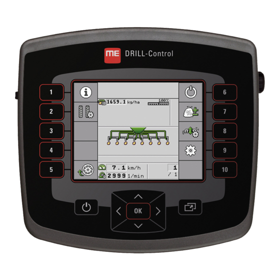
About the on-board integrated display/controller Overview of keys Overview of keys DRILL-Control on-board integrated display/controller Keys Function Switches the on-board integrated display/controller on and off. Confirms entries. Creates screenshots. Navigate within individual screens. Performs the function shown on the screen. - Page 10 About the on-board integrated display/controller Information on the nameplate Information on the nameplate Client’s item number Operating voltage If the product was manufactured for an The product may only be connected to agricultural machinery manufacturer, the voltages within this range. agricultural machinery manufacturer's item number will be shown here.
-
Page 11: About These Operating Instructions
Who is the target user for these Operating Instructions? About these Operating Instructions Who is the target user for these Operating Instructions? These Operating Instructions are intended for operators of seeders equipped with the DRILL-Control on-board integrated display/controller manufactured by Müller-Elektronik. Scope of the instructions These instructions describe all of the functions that can be actuated with the on-board integrated display/controller. - Page 12 About these Operating Instructions Layout of references References can be identified by their square brackets and an arrow. The number following the arrow shows you on what page the section starts where you can find further information. V3.20151130_rev.2 30283620-02-EN...
-
Page 13: Mounting And Installation
Mounting and installation Installing the on-board integrated display/controller Mounting and installation Installing the on-board integrated display/controller DRILL-Control - rear view Attachment for the bracket. 8-pin flange socket. ASD interface for the use of SECTION- Control. Power connection cable USB port For connection to the battery connection To connect a USB memory device. -
Page 14: Installing The Revolution Sensors
Mounting and installation Installing the sensors on the implement 4.2.1 Installing the revolution sensors Hall element sensors are suitable as revolution sensors. Functional principle The Hall element establishes a connection between the green and the white cable cores. To do so, the magnet must be held with the red side in front of the blue cap on the sensor. -
Page 15: Installing The Fill Level Sensor
Mounting and installation Installing the sensors on the implement Connector pin assignment 3-pin AMP connector Cable color Designation white brown 12VE green Signal Spare part number Item number Designation 30303623 Hall element sensor with 3-pin AMP connector, switching distance: 5-10 mm 4.2.2 Installing the fill level sensor Capacitive sensors are suitable as fill level sensors. -
Page 16: Installing The Working Position Sensors
Mounting and installation Installing the sensors on the implement Connector pin assignment 3-pin AMP connector Cable color Designation blue brown 12VE black Signal Spare part number Item number Designation 30303650 Capacitive sensor with 3-pin AMP connector 4.2.3 Installing the working position sensors Reed contact sensors are suitable as working position sensors. -
Page 17: Installing The Speed Sensor
Mounting and installation Installing the sensors on the implement Schematic overview Min. 25 mm Attachment angle Distance 15-25mm Sensor (red cap) South pole of the magnet (red side) Magnet (nonmagnetic attachment, e.g. V2A, copper, brass) Connector pin assignment 3-pin AMP connector Cable colour Designation white... - Page 18 Mounting and installation Installing the sensors on the implement Spare part number Item number Designation 30258321 Vansco type 740 radar sensor with 1 m cable and with 3-pin AMP connector V3.20151130_rev.2 30283620-02-EN...
-
Page 19: Basic Control Principles
Basic control principles Switching on the on-board integrated display/controller Basic control principles Switching on the on-board integrated display/controller You have installed the on-board integrated display/controller. [➙ 13] Procedure - Switch on the on-board integrated display/controller. ⇨ The work screen appears. Layout of the work screen The work screen is the part of the screen where you can see the current status of the implement based on the icons shown. - Page 20 Basic control principles Layout of the work screen ▪ - The left bout marker is being used and the change mode of the bout marker is activated. ▪ - The right bout marker is being used and the change mode of the bout marker is activated.
-
Page 21: Configuring The Basic Settings Of The On-Board Integrated Display/Controller
Configuring the basic settings of the on-board integrated display/controller Setting the date / time Configuring the basic settings of the on-board integrated display/controller Setting the date / time Procedure 1. On the work screen, press: > > ( ) > - Navigate to the date and time. - Page 22 Configuring the basic settings of the on-board integrated display/controller Selecting the language - Confirm. ⇨ You have selected the desired language. ⇨ When you exit the screen, the on-board integrated display/controller is restarted. V3.20151130_rev.2 30283620-02-EN...
-
Page 23: Operating The Implement On The Field
Operating the implement on the field Setting target rate Operating the implement on the field Setting target rate On the "Settings / Metering Unit" screen, you can configure or view the following parameters for each metering unit: ▪ "Metering Unit" Defines the currently selected metering unit. -
Page 24: Filling Metering Cells With Seed
Operating the implement on the field Filling metering cells with seed ⇨ The "Calibration" screen appears. 5. In the input box under the text "Speed correct?", enter the speed you want to use later on when seeding. - Fill the metering cells with seed or with fertilizer. ⇨... -
Page 25: Stop Seeding
Operating the implement on the field Stop seeding - Start seeding. Stop seeding Procedure - Stop seeding. ⇨ On the work screen, the following message appears: "Application is stopped." ⇨ All of the metering drives are stopped. Adjusting the target rate during operation You can adjust the target rate while working. -
Page 26: Configuring The Tramline Control
Operating the implement on the field Using tramline control Areas on the work screen that are relevant for the creation of tramlines A tramline is being created. Length of the tramline rhythm Number of tracks until the tramline rhythm is repeated. -
Page 27: Selecting Tramline Rhythm
Operating the implement on the field Using tramline control ▪ One tramline mechanism on one side of the seeder. ▪ Two tramline mechanisms on one side of the seeder. ▪ One tramline mechanism on one side and two tramline mechanisms on the other side of the seeder. ▪... -
Page 28: Creating An Even Tramline Rhythm
Operating the implement on the field Using tramline control Procedure This is how to select the proper tramline rhythm: You know the working width of your implement. You know the working width of your sprayer. You know which side of your seeder is used to create tramlines and how many tramline mechanisms your seeder has on each side. - Page 29 Operating the implement on the field Using tramline control Creating tramlines on both sides of the seeder simultaneously Example ▪ The figure shows the 4S tramline rhythm. ▪ The tramlines are created during track 2. (ex.: working width of the sprayer = 12 m, working width of the seeder = 3 m) ▪...
- Page 30 Operating the implement on the field Using tramline control Creating tramlines on one side of the seeder and with only one tramline mechanism Example ▪ The figure shows an individual tramline rhythm. ▪ The tramlines are created during tracks 2 and 3. (ex.: working width of the sprayer = 12 m, working width of the seeder = 3 m) Working start at the left field edge Possible position...
- Page 31 Operating the implement on the field Using tramline control Possible position Result of the RhNo. Length Left Right of the flaps calculation Creating tramlines on one side of the seeder and with two tramline mechanisms Example ▪ The figure shows an individual tramline rhythm. ▪...
-
Page 32: Creating Uneven Tramline Rhythms
Operating the implement on the field Using tramline control Possible position Result of the RhNo. Length Left Right of the flaps calculation Working start at the right field edge Possible position Result of the RhNo. Length Left Right of the flaps calculation Creating uneven tramline rhythms Uneven tramline rhythms are always created in one track. -
Page 33: Creating Special Tramline Rhythms
Operating the implement on the field Using tramline control Possible position Result of the RhNo. Length Left Right of the flaps calculation Creating special tramline rhythms Special tramline rhythms are always created in four tracks. Special tramline rhythms can only be created if the tramlines are created with both sides of the seeder. - Page 34 Operating the implement on the field Using tramline control Possible position Result of the RhNo. Length Left Right of the flaps calculation 2.67 3.33 4.67 5.33 6.67 9.33 Working start at the right field edge Possible position Result of the RhNo.
- Page 35 Operating the implement on the field Using tramline control Possible position Result of the RhNo. Length Left Right of the flaps calculation 2.67 3.33 4.67 5.33 6.67 9.33 30283620-02-EN V3.20151130_rev.2...
-
Page 36: Programming Individual Tramline Rhythms
Operating the implement on the field Operating the hydraulic system with the job computer 7.7.4 Programming individual tramline rhythms If you realize that the tramline rhythms stored do not match your work method, you can program an individual tramline rhythm. Procedure 1. -
Page 37: Using The Waterhole Mode
Operating the implement on the field Operating the hydraulic system with the job computer Function icon Meaning For example, to work on the headlands. Deactivate both bout markers. Lift the bout marker to pass over obstacles. The implement itself is not lifted. -
Page 38: Viewing Results
Operating the implement on the field Viewing results Procedure The implement is lowered. 1. On the work screen, press: > ⇨ The icon for the waterhole mode appears on the work screen: - Terminate the waterhole mode. ⇨ The icon for the waterhole mode disappears. Viewing results 7.9.1 Results... - Page 39 Operating the implement on the field Viewing results Procedure 1. On the work screen, press: > ⇨ "Total results" screen appears. 30283620-02-EN V3.20151130_rev.2...
-
Page 40: Configuring The On-Board Integrated Display/Controller For Work
Configuring the on-board integrated display/controller for work Selecting and configuring the speed source Configuring the on-board integrated display/controller for work Selecting and configuring the speed source You must enter the source from which the on-board integrated display/controller obtains the current speed. -
Page 41: Entering The Simulated Speed
Configuring the on-board integrated display/controller for work Associating products with a hopper 8.1.2 Entering the simulated speed To test the proper functioning of a sensor, you can simulate a speed. CAUTION Injury caused by working implement If the function is activated when the implement is at a standstill, the driver can activate functions that can otherwise only be activated during travel. -
Page 42: Configuring The Implement Equipment
Configuring the implement equipment General information on the configuration Configuring the implement equipment General information on the configuration 9.1.1 Performing the configuration The equipment of the implement is configured in a separate area of the application. You will find different parameters within the area. Procedure To perform the calibration: 1. -
Page 43: Sequence Of The Configuration
Configuring the implement equipment General information on the configuration Function icon Meaning Starts the screen for the next part of the same type. Starts the screen for the next part of the same type. Password entry Return 9.1.3 Sequence of the configuration The configuration differs according to the machine type that you are using and the implement equipment. -
Page 44: Configuration Of The Implement
Configuring the implement equipment Configuration of the implement Configuration of the implement For the configuration of the implement, you must set the basic equipment of the implement. The implement must always be configured first. 9.2.1 "Number of rows" parameter Enter the number of rows that the implement works with. Seed and fertilizer are counted separately. -
Page 45: Gear Ratio" Parameter
Configuring the implement equipment Configuration of the rows 1. On the "Settings / Implement" screen, press: > ⇨ You can configure the metering units. 9.4.1 "Gear ratio" parameter For each metering unit, enter the gear ratio between the metering shaft and the motor shaft. Example: A gear ratio of 50/1 means that the metering shaft must rotate 50 times for the motor shaft to rotate once. -
Page 46: Working Width" Parameter
Configuring the implement equipment Configuration of the sections 9.6.1 "Working width" parameter Enter the respective working width for each section. V3.20151130_rev.2 30283620-02-EN... -
Page 47: Using The System Functions Of The On-Board Integrated Display/Controller
⇨ If the export was successful, the configuration will be saved as a bin file on the USB memory device in the "USB-BOX\me-drill-control\export" folder. 10.3 Importing a configuration You can import a configuration from a USB memory device to your DRILL-Control. Procedure 1. Save the desired configuration on a USB memory device in the folder: "USB-BOX\me-drill- control\import". -
Page 48: Updating The On-Board Integrated Display/Controller
Using the system functions of the on-board integrated display/controller Updating the on-board integrated display/controller 10.4 Updating the on-board integrated display/controller If a new software version is available for your on-board integrated display/controller, you can update Procedure You have received an update file in zip format from Müller-Elektronik. 1. -
Page 49: Troubleshooting
Troubleshooting Performing diagnostics Troubleshooting 11.1 Performing diagnostics In the diagnostic, you can read the measured values for all of the pins that are connected to the junction box. In addition, you can test whether the functions of the job computer are working as desired. - Page 50 Troubleshooting Performing diagnostics Currently measured current flow of the function. The value of the power measurement always increases or decreases proportionally. Example: The faster an electric motor is turning, the higher the value of the power measurement ▪ "Input" – "low" The function is deactivated.
-
Page 51: Checking The Version Numbers
Troubleshooting Checking the version numbers 1. On the work screen, press: > > ( ) > ⇨ The "Diagnostic" screen will appear. ⇨ On the screen, you can see the measured values and possible settings for the individual functions. Procedure 11.2 Checking the version numbers Procedure... - Page 52 Troubleshooting Alarm messages Alarm text Possible cause Remedial measure range exceeded. or lower than the set speed. metering roll. Metering shaft is stationary. The revolution sensor on the metering shaft does Stop immediately! not register any movement of the metering shaft. Remediate the cause.
- Page 53 Troubleshooting Alarm messages Alarm text Possible cause Remedial measure Procedure is not allowed A task is activated in the ISOBUS-TC application. Deactivate the task. while a task is activated in the ISOBUS-TC application. Seed flow detected in a row The row is defective. Check the row.
-
Page 54: Technical Specifications
Technical specifications Technical specifications of the on-board integrated display/controller Technical specifications 12.1 Technical specifications of the on-board integrated display/controller Parameter Value Operating voltage 10 -16 V Operating temperature -20°C - +60°C Storage temperature -30°C - +70°C Dimensions (W x H x D) 220 x 205 x 90 mm In accordance with ISO 14982 / CISPR25 Interference suppression level 4... -
Page 55: Connector Pin Assignment
Technical specifications Connector pin assignment 12.2 Connector pin assignment 12.2.1 8-pin flange socket These abbreviations are used in the following table: ▪ VE – Electronics voltage ▪ VL – Power voltage 8-pin flange socket Signal 8-pin flange socket Signal Pin no. Pin no. -
Page 56: Hydraulic System Of The Implement
Technical specifications Hydraulic system of the implement 39-pin connector Signal 39-pin connector Signal 39-pin connector Signal Pin no.: Pin no.: Pin no.: speed sensor Engine speed 12VE sensor Fan speed sensor Lower level sensor Upper level sensor Calibration switch Work position sensor Potentiometer V-Namur... -
Page 57: Explanation Of The Signals In The Assignment Plan
Explanation of the signals in the assignment plan Explanation of the signals in the assignment plan There is an assignment plan for each implement model. You can obtain the assignment plan corresponding to your implement from your contact person at Müller-Elektronik. In the next tables, you will find explanations for the texts that are found on the assignment plan. -
Page 58: Notes
Notes Notes V3.20151130_rev.2 30283620-02-EN...
Need help?
Do you have a question about the DRILL-Control and is the answer not in the manual?
Questions and answers