
Related Manuals for Conrad GX110


Summary of Contents for Conrad GX110
- Page 1 OPERATING INSTRUCTIONS Version 02/16 GSM Remote Switching/Measuring/Alarm System „GX110“ Item no. 199285...
-
Page 2: Table Of Contents
Table of Contents Page 1. Introduction ........................................ 4 2. Intended Use ......................................4 3. Explanation of Symbols ....................................5 4. Scope of Delivery ....................................... 5 5. Safety Information ...................................... 6 6. Operating conditions ....................................7 7. Input Function Overview .................................... 7 8. - Page 3 Page 19. Troubleshooting ....................................... 32 a) Possible Errors during Communication ............................... 32 b) Possible Errors during Logon ................................32 c) Possible Errors during Response ................................ 32 d) Possible Errors during „INCALL“ ................................. 33 e) Possible Errors of TEMP1-4 ................................33 f) Possible Errors of IN1 and IN2 ................................
-
Page 4: Introduction
Tel. no.: +49 9604 / 40 88 80 Fax. no.: +49 9604 / 40 88 48 E-mail: tkb@conrad.de Mon. to Thur. 8.00am to 4.30pm, Fri. 8.00am to 2.00pm 2. Intended Use This GSM switching module is used for activating/deactivating devices via the GSM network, automatic temperature control, remote request of the status of all inputs and outputs and the generation of SMS and email messages. -
Page 5: Explanation Of Symbols
• Suitable connection lines for supply voltage and connection of the in- and outputs • Optionally, depending on use of the in- and outputs, you additionally need up to 12 relays (Conrad item no. 502892) or relay PCBs (Conrad item no. 585498) •... -
Page 6: Safety Information
5. Safety Information This GSM module left the factory in perfect condition in terms of safety engineering. The user must observe the safety instructions and warnings contained in these operating instructions to preserve this condition and to ensure safe operation. Please read the operating instructions completely before commissioning. -
Page 7: Operating Conditions
• Two temperature inputs „T1“ and „T2“ are used for temperature measurement and control. One temperature sensor each (e.g. Conrad item no. 198896) can be connected to the two temperature inputs. These inputs are used, e.g. to monitor room temperatures and for targeted control of heating systems. -
Page 8: Output Function Overview
• The output „FLS“ has no function. • The output „INV“ is reversed at each rising flank at the input. A relay (e.g. Conrad item no. 502892) or the relay PCB (Conrad item no. 585498) can be directly connected to the output. This is used, e.g. for power surge switches with several switches controlling a joint consumer as in the case of several light buttons in a hallway. -
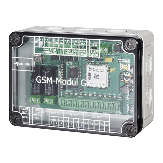
Page 9: Gsm Module Connections
Minus/- to the right terminal. 4 V/DC are applied to the left terminal. Connection for both temperature sensors (Conrad item no. 198896): Plus/+ (white) is connected to the left screw terminal, the signal (red) to the centre and Minus/- (black) to the right screw terminal. - Page 10 Minus/- is connected to the left screw terminal and Plus/+ to the right terminal. A relay (Conrad item no. 502892) or the relay PCB (Conrad item no. 585498) can be directly connected to the screw terminals. Red LEDs are applied to all outputs. The LEDs light up once an output is activated and thus serve as status LEDs.
-
Page 11: Required Steps And Information For Commissioning
10. Required Steps and Information for Commissioning Important! To take the GSM module into operation properly, the following steps must be performed strictly in the indicated order. Non-observance may lead to functions not being warranted, configuration being impossible and/or the SIM card being locked by the GSM module. a) Software Installation Before taking up any work at the GSM module, you have to install the control software and the required drivers on your computer. -
Page 12: C) General Settings Of The Control Software
c) General Settings of the Control Software Use the button „D/E“ to switch the program language between German and English in the control software. The help file is opened in the corresponding language. Click the button „General Settings“. An interface appears for entering the SIM card’s PIN number, the desired phone numbers (PHONE) and email addresses (MAIL). -
Page 13: G) Email With Smtp And Gprs
15 digits and is only displayed encrypted. You can enter up to 4 email addresses („MAIL“) in „General Settings“ (e.g. max.mustermann@conrad.de). You have to enter all email addresses to which the GSM module is supposed to send an email. -
Page 14: Initial Commissioning Of The Gsm Module (Test Configuration)
11. Initial Commissioning of the GSM Module (Test Configuration) At initial commissioning, observe that the removed PCB is not short-circuited by metal or live parts. When connecting the operating voltage, always ensure correct polarity. Avoid short circuits at the GSM module connections. If this is not observed, the GSM module will be destroyed. - Page 15 • Switch on the supply voltage now. • Start the GSM module control software on your computer. Select the COM port determined in your operating system’s device manager in the software under „Communication“. • Then click „Status“ and check whether a connection has been established.
- Page 16 • Send the change to the module in „Communication“ (click the button „Send“). • The message „All data transferred!“ must appear. • Switch off the operating voltage again. • The saved data is preserved in the module even after switching the operating voltage off and on again.
- Page 17 Due to the great number of SIM cards and providers on the market, you may receive the message „Wrong pin code! Waiting for data“ in the status window in spite of the SIM PIN being set correctly and the configuration being transmitted correctly. In this case, take a different provider’s card, perform the required changes to the configuration according to the instructions and test the GSM module again.
-
Page 18: General Information On The „Status" Button
12. General Information on the „Status“ Button The module performs a reset and dials into the GSM network once a configuration has been transferred to the GSM module. Once the green GSM LED flashes slowly (LED on for 1 second, then 3 seconds break), the status of all inputs and outputs can be displayed in „Communication“. -
Page 19: Determination Of Phone Numbers
The following values apply for the „Level“ display value: Status indicator Bar display control software Meaning 5 red bars no reception or not logged in 1 to 20% 1 red bar no reception 21 to 36% 1-2 green bars bad reception 37 to 56% 3 green bars minimum permissible reception strength... -
Page 20: Response / Error Message
You are sending an SMS to the GSM module with the text that is stored in the GSM module as „Response / Error Message“ (e.g. „Reply“). The GSM module responds with, e.g.: CONRAD GX110 T1=23C, T2=27C, TMP1-4=L,L,L,L, IN1-2=L,L, ADC=0mV, INCALL=L, SMS1-4=H,L,L,L, LOG=L, DEL=L, INV=L, ALARM=H, BILDER=0, PEGEL=60% -ENDE- The above message means that the temperature sensor has measured 23 °C at connection „T1“... -
Page 21: Installation And Configuration Of The Outputs
15. Installation and Configuration of the Outputs a) „INCALL“ Output The „INCALL“ output switches on for a defined time when the GSM module is called. Because the GSM module does not pick up, this is free of charge! Just call the GSM module and let it ring a few times. Then the „INCALL“ output switches on for the time set in the control software and then off again automatically. -
Page 22: B) Sms Outputs „Sms1" To „Sms4
The outputs „SMS1“ to „SMS4“ can be activated or deactivated by sending an SMS to the GSM module. A relay is already connected to the output „SMS1“. A relay (Conrad item no. 502892, not included in the delivery) or a relay PCB (Conrad item no. 585498, not included in the delivery) can be directly connected to the remaining outputs. -
Page 23: C) Temperature Outputs „Tmp1" To „Tmp4
(approx. 4 V, max. 100 mA) can also directly affect other electronic circuits when the output is active. However, a relay (Conrad item no. 502892) or the relay PCB (Conrad item no. 585498) can also be be directly connected to these outputs. - Page 24 (observe permissible operating voltages, see „Technical Data“) or install additional relays (Conrad item no. 502892) or relay PCBs (Conrad item no. 585498). Also observe the notes in these operating instructions, chapter 14 „Temperature Inputs T1 and T2“.
-
Page 25: D) Alarm Output „Ala
ADC, the logic, the delay and the inverter. A relay (Conrad item no. 502892, not included in the delivery) or a relay PCB (Conrad item no. 585498, not included in the delivery) can be directly connected to the output. The output has an indicator LED that visually displays the switching process. -
Page 26: G) Delay Output „Del
A relay (Conrad item no. 502892, not included in the delivery) or a relay PCB (Conrad item no. 585498, not included in the delivery) can be directly connected to the output. The output has an indicator LED that visually displays the switching process. -
Page 27: H) Logic Output „Log
NAND, OR, NOR or EXOR for activation and deactivation. A relay (Conrad item no. 502892, not included in the delivery) or a relay PCB (Conrad item no. 585498, not included in the delivery) can be directly connected to the output. The output has an indicator LED that visually displays the switching process. -
Page 28: Installation And Configuration Of The Inputs
16. Installation and Configuration of the Inputs Note: There is a separate 10-minute-lockout for each of the inputs: If a text message has been delivered because of a signal at the input, then this input is blocked for 10 minutes. This is regardless of what happens at this input - it is sent no text message before the end of 10 minutes! Each input has its own 10-minute-lockout. -
Page 29: B) Adc Input
b) ADC Input The ADC input can measure voltages from 0 to 14 V/DC. The voltage to be measured is connected to the middle input (ADC) and the right input (minus). An auxiliary voltage of +4 V/DC is output at the left terminal (+). The GSM module can trigger a message by SMS above and below a voltage set. -
Page 30: Sms Service
17. SMS Service With this GSM module, you can easily write and send an SMS as on a mobile phone. The SMS is then sent by the GSM module via the inserted SIM card. Therefore, also observe the costs resulting from sending SMS. Once the GSM module has dialled into the GSM network, you can gene- rate an SMS text with the button „SMS Service“... -
Page 31: Final Assembly
18. Final Assembly Before final assembly, first get familiar with all functions and try out the device in all applications you want to install. To install the GSM aerial, remove the protective foil from the GSM aerial. Glue the aerial to the assembly site you have already tested for good, interference-free reception as described in chapter „Configuration of the SIM-Card“. -
Page 32: Troubleshooting
19. Troubleshooting a) Possible Errors during Communication Drivers not installed: • Re-install „CP210xVCPInstaller.exe“ on the CD in directory „MCU“ Drivers not installed correctly: • Uninstall and reinstall drivers COM-Port above COM10: • Move COM port: Go to Properties / Connection Settings / More... / COM port number in the device manager and find a free COM-port below COM10 Software message „ERROR: No answer received from module!“: •... -
Page 33: D) Possible Errors During „Incall
d) Possible Errors during „INCALL“ Message „Participant not available“ • Module has not logged on to the GSM network yet: Wait briefly until the module has logged on or move the aerial to another place No phone number displayed in the status •... -
Page 34: H) Possible Errors Of Sms1
h) Possible Errors of SMS1 No phone number displayed in the status • Activate caller ID transmission in the mobile phone SMS arrives but SMS1 is not switched • Wrong phone number entered • Caller ID transmission deactivated • Called from another mobile phone or configuration not transmitted •... -
Page 35: Circuit Example
At the end of its service life, dispose of the product according to the relevant statutory regulations. 23. Declaration of Conformity (DOC) We, Conrad Electronic SE, Klaus-Conrad-Straße 1, D-92240 Hirschau, hereby declare that this product complies with the fundamental requirements and the other relevant regulations of the directive 1999/5/EC. -
Page 36: Technical Data
Matching relay for all outputs ............Conrad item no. 502892 Matching relay PCB for all outputs ........... Conrad item no. 585498 Matching temperature sensor for the inputs T1 and T2 ....Conrad item no. 198896 Matching replacement aerial ............Conrad item no. 199399... - Page 40 Legal Notice This is a publication by Conrad Electronic SE, Klaus-Conrad-Str. 1, D-92240 Hirschau (www.conrad.com). All rights including translation reserved. Reproduction by any method, e.g. photocopy, microfilming, or the capture in electronic data processing systems require the prior written approval by the editor. Reprinting, also in part, is prohibited. This publication represent the technical status at the time of printing.
Need help?
Do you have a question about the GX110 and is the answer not in the manual?
Questions and answers