Table of Contents
Advertisement
Advertisement
Table of Contents

Related Manuals for K&R ACD320 Series

Summary of Contents for K&R ACD320 Series
- Page 2 The terminals of inverter must be connected to the ground correctly. The Input power line absolutely can not be connected to the Output terminal U/T1、 V/T2 and W/T3. Application range of this manual: This manual is applied to ACD320 Series Inverters of our company.
-
Page 3: Table Of Contents
ACD320user manual Catalogue Chapter 1 Safety information and use notice points........1 1.1 Safety precautions ..................1.2 Use range ......................1.3 Use notice points ..................... 1.4 Scrap notice points ..................Chapter 2 Type and specification of the inverter.........4 2.1 Incoming inverter inspect ................ -
Page 4: Table Of Contents
................7.4 Failure reset ....................Chapter 8 Maintenance................126 8.1 Routine maintenance ................8.2 Inspection and replacement of damageable parts ......8.3 Repair guarantee ..................8.4 Storage ......................Chapter 9 Appendix..................129 Appendix 1 ACD320 series serial communication protocol .... - Page 5 ACD320user manual Catalogue Appendix 2 All BrakingResistors & Braking Units Use in AC Drives ..........................Appendix 3 Parameter illustration of the inverter specially used for one driving one constant pressure water supply ........Appendix 4 Example for one driving two constant pressure water supply controlling card and water supply mode that one for use and one for supplement(one driving two circularly running)...
-
Page 6: Chapter 1 Safety Information And Use Notice Points
ACD320 User Manual Safety information and use notice points Chapter 1 Safety information and use notice points In order to ensure the safety of your personal and equipment, please read this chapter of content conscientiously before using the inverter . 1.1 Safety precautions There are three kinds of safety relevant warnings in this service manual.They are as follows:... -
Page 7: Use Range
ACD320 User Manual Safety information and use notice points 1.2 Use range (1) This inverter is only suitable for three phases AC asynchronous motor in general industrial field. (2) When apply inverter to such equipments that arerelated much to the life, great property, safety devices etc., please must handle cautiously and consult producer. -
Page 8: Scrap Notice Points
ACD320 User Manual Safety information and use notice points range allowed, otherwise should vary voltage or order special inverter. (10) In the condition of altitude above 1000 meters, should use the inverter in lower volume, reduce output current by 10% of specified current after each 1500 meters height increasing. -
Page 9: Chapter 2 Type And Specification Of The Inverter
ACD320 User Manual Type and specification of the inverter Chapter 2 Type and specification of the inverter 2.1 Incoming inverter inspect (1) Check if there is a damage during transportation and inverter itself has damage or fall-off parts (2) Check if parts presented in packing list are all ready. (3) Please confirm rated data of the inverter is in line with your order requirement. -
Page 10: Series Type Explanation
Type and specification of the inverter ACD320user manual 2.4 Series type explanation Table 2-1 series type explanation Input Rated power Rated input Rated output Adapted Inverter type voltage(V) (KVA) current(A) current(A) motor(KW) ACD320-2T0.4 ACD320-2S0.4 ACD320-2T0.7 0.75 ACD320-2S0.7 ACD320-2T1.5 14.0 Three phase ACD320-2S1.5 220V range: ACD320-2T2.2... - Page 11 Type and specification of the inverter ACD320user manual Input Rated power Rated input Rated output Adapted Inverter type voltage(V) (KVA) current(A) current(A) motor(KW) ACD320-4T132 192.0 256.0 253.0 ACD320-4T160 231.0 307.0 304.0 ACD320-4T185 237.0 340.0 330.0 ACD320-4T200 250.0 385.0 377.0 ACD320-4T220 280.0 430.0 426.0...
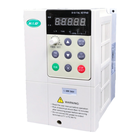
- Page 12 Type and specification of the inverter ACD320user manual 2.5 Appearance and parts name explanation ○ 1 :Screw hole ○ 2 :Nameplate ○ 3 :Motor output terminal lower-cover ○ 4 :Operation surface ○ 5 :Power input terminal upper-cover ○ 6 :Heat radiation vent ○...
-
Page 13: Out Size
Type and specification of the inverter ACD320user manual 2.6 Out size 2.6.1 Keypad out size For example:36.5[1.44] Unit:millimeter [inch] Fig.2-4 Fig.a Outer dimension Fig.2-4 Fig.b Outer dimension Fig.2-4 Fig.c Outer dimension - 8-... - Page 14 Type and specification of the inverter ACD320user manual Out-pull panel indicator A- using keypad sheath Out-pull panel indicator B- not using keypad sheath - 9-...
- Page 15 Type and specification of the inverter ACD320user manual 2.6.2 Chassis out size 2.6.2.1 Plastic chassis out size(wall mounted) 2.6.2.2 Metals chassis out size(wall mounted) - 10-...
- Page 16 Type and specification of the inverter ACD320user manual 2.6.2.3 Metals chassis outline dimention drawing (clothes closet) 2.6.2.4 Metals chassis outline dimention drawing (the Cabinet machine and the wall hangs machine) - 11-...
- Page 17 Type and specification of the inverter ACD320user manual Size table Size(mm) Chassis Shell Specification and type ACD320-2T0.4GB ACD320-2S0.4GB ACD320-2T0.75GB ACD320-2S0.75GB ACD320-2T1.5GB 150.0 ACD320-2S1.5GB ACD320-4T0.75GB 118.0 172.5 185.0 105.5 ACD320-4T1.5GB ACD320-4T2.2GB ACD320-2T2.2GB ACD320-2S2.2GB 170.0 ACD320-4T3.0GB/4.0 ACD320-4T4.0GB ACD320-4T5.5LB ACD320-4T5.5GB/7.5 160.0 235.0 247.0 148.0 186.0 ACD320-4T7.5GB...
-
Page 18: Product Technic Index And Specification
Type and specification of the inverter ACD320user manual ACD320-4T500G/560L K630 ACD320-4T560G/630L 1260.0 2290 620.0 ACD320-4T630G/700L Note:H1 is the height of wall mounted inverter, H2 is the height of clothes closet inverter. 2.7 Product technic index and specification Item Specifications Maximum frequency 600.00Hz 1kHz~15kHz;the carrier frequency will be automatically adjusted Carrier frequency... - Page 19 Type and specification of the inverter ACD320user manual Auto voltage It can keep constant output voltage automatically in case of change regulation (AVR) of mains voltage. “Digging machine” feature, which limit torque Torque limit and automatically and prevent frequent over current tripping during the control running process;...
- Page 20 Type and specification of the inverter ACD320user manual Indoor, not bare to sunlight, not dust, no corrosive gas, no flammable gas, Using Place no oil fog, no water drop or salt etc. altitude Lower than 1,000 meters -10 ℃ Celsius to +40 ℃ Celsius (derated when used in the ambient ambient temperature temperature of 40 ℃...
-
Page 21: Chapter 3 Installation And Wiring
ACD320user manual Installation and wiring Chapter 3 Installation and wiring 3.1 Installation ambient 3.1.1 Demand for installation ambient (1) Installed in drafty indoor place, ambient temperature within -10ºC~40ºC, need external compulsory heat sink or reduce the volume if temperature exceeds 40ºC. (2) Avoid installing in place with direct sunlight, much dust, floating fibre and metal power. -
Page 22: Electrical Installation
ACD320user manual Installation and wiring The user shall focus on the heat dissipation issues when installing the inverter, and pay attention to the following points: 1) Install the inverter vertically so that the heatmay be expelled from the top, but do not install the inverter upside down.When twoVariable SpeedDrives are mounted up and dow n, an air flow diverting plate should be fixed in between as shown in Fig. - Page 23 ACD320user manual Installation and wiring 4T75 25*2(50) 35*2(70) 4T90 35*2(70) DZ20-400(250A) 50*2(95) 4T110 4T132 CJ20-250 50*2(95) 4T160 DZ20-400(350A) 70*2(150) 4T185 4T200 DZ20-400(400A) CJ20-400 70*2(150) 70*2(150) 16*2(35) 4T220 DZ20-630(500A) 95*2(185) 95*2(185) 4T250 CJ20-630 25*2(50) 4T280 DZ20-630(600A) 120*2(240) 120*2(240) 4T315 4T355 DZ20-800(800A) CJ20-800 150*2(300) 150*2(300)
-
Page 24: Peripheral Equipment
ACD320user manual Installation and wiring 3.2.2 周边设备配线图及其应用注意事项: Wiring Diagram of Peripheral Equipment and the notice ①Power supply:voltage levels:220V,400V。 ②fuse or the Electric leakage chopper Input power supply ① Fuse or leaking current breaker Please use fuse that conform to the rated voltage and current level of inverter. -
Page 25: Basicwiring Diagram
ACD320user manual Installation and wiring 3. 3 BasicWiring Diagram Usersmust connect wires according to the following circuit diagram shown below. Below 7.5KW - 20-... - Page 26 ACD320user manual Installation and wiring 11~30KW: - 21-...
- Page 27 ACD320user manual Installation and wiring Above 37KW : Fig.3-3 Basic running wiring diagram Note: Breaking resistor terminals (B2/B1) for the inverter of 15KW or below. Braking unitand and DC link reactor terminals (P1/P2/DC-)for the inverter 18.5KW~30KW. Braking unitand terminals (DC+/DC-)for the inverter above 37KW. 1、...
-
Page 28: Main Circuit Terminals Andwiring
ACD320user manual Installation and wiring 3. 4 Main Circuit Terminals andWiring Danger ★Wiring can only be done after the mains input is cut off, otherwise therewill be danger of electric shock! ★Only qualified and trained engineer can perform thewiring, otherwise there will be danger of electric shock! ★Grounding cable must be grounded, otherwise there will be danger of electric shock or fire! -
Page 29: Control Terminals And Wiring
ACD320user manual Installation and wiring When selecting the brake unit for the inverter above 18.5kW,pay attention that the polarity of (DC+) and (DC-) cannot be reverse, otherwise the inverter may burn or be damaged. The cable length of brake unit shall be less than 10 mand twisted pair cables shall be used. Do not connect the brake resistor directly to the DC bus, otherwise the inverter may burn or be damaged. - Page 30 ACD320user manual Installation and wiring 2)Function of Control Terminals: Item Symbol Name Function description spec Multi-function MI1-COM input terminal 1 Used for multi-function input Multi-function terminal, for detailed see Chapter MI2-COM input terminal 2 6 Section terminal function Optocoupler isolation Multi-function MI3-COM input terminal 3...
- Page 31 ACD320user manual Installation and wiring Provide analog voltage/current output, for detailed see F2.22 Voltage output range: Analog value parameter description, output 0~10V AO1-GND voltage/current optioned by J3, Current output range: output 1 factory default output voltage. 0~20mA (reference ground: GND) Provide analog voltage/current Voltage output range: output, for detailed see F9.09...
- Page 32 ACD320user manual Installation and wiring cable shall be used and the cable shall be as short as possible and the length shall not exceed 20m, as shown in the figure 3-6: Fig. 3 -6 Analog Input Terminal of ACD Series Inverter If the analog signal is severely disturbed, filter capacitor or ferrite core shall be installed at the analog signal source as shown in the Fig.
- Page 33 ACD320user manual Installation and wiring Fig.3-8 Analog output terminal wiring diagram (3) MI1~MI6、FWD、REV terminal wiring method A. the mode of dry contact ① Use interior 24V power supply, when input polarity is PNP , the wiring mode as Fig.3-9. Fig.3-9 Source Electrode Connection mode when using interior 24V power supply ②...
- Page 34 ACD320user manual Installation and wiring The use of inverter internal +24V power supply, external controller for NPN typecommon emitter connection pole output,As shown in Figure 3-11。 Fig.3-11 Source Electrode Connection mode when using interior 24V power supply ②The use of inverter internal +24V power supply, external controller for PNP typecommon emitter connection pole output,As shown in Figure 3-12。...
-
Page 35: Emc Issues
ACD320user manual Installation and wiring Otherwise, when the digital output terminal has output, the DC 24V power supply and output circuit will be damaged immediately. Fig.3-13 Schematic diagram for connection of digital output terminal (5)Delay output terminal RA/B/C、TA/B/C wiring If driving an inductive load(such as the electromagnetic relay,the contactor), surgevoltage absorption circuit should be installed, such as RC absorption circuit(Pay attention that its leaking current should be less than keeper current of the contactor or relay controlled by it), voltage-sensible resistance, and diode,etc.(If it is used in DC electromagnetic loop, check the... - Page 36 ACD320user manual Installation and wiring EMI issue is mainly toreduce the EMI of inverter. Methods: A) Inverter and other equipment shall be well grounded and the grounding resistance shall be less than 5ohm. B) Inverter's power cables shall be vertical instead of parallel with the control cables. C) For the applicationwith strong disturbance, the power cables from the motor to the inverter shall be shielded and the shielding layer shall be grounded.
- Page 37 ACD320user manual Installation and wiring C) Ground the external equipment and eliminate the disturbance of the leakage current fromthe inverter's grounding cable. 3.6.3 Leakage current The inverter has two kinds of leakage current, one is the grounding leakage current and another is the leakage current between the lines: 1) Grounding leakage current: The distributed capaci tance exists between the cables and the ground, and the bigger the...
-
Page 38: Chapter 4 Digital Keypad Operation
ACD320user manual Digital Keypad Operation Chapter 4 Digital Keypad Operation 4.1 Description of the DigitalKeypad DigitalKeypad Parts and Functions This digital keypad module includes two parts: display panel and a keypad.The display panel allows the user to program the AC drive, aswell as view the different operating parameters. The keypad is the user interface to the AC motor drive. -
Page 39: Modify And Check The Function Codes
4.2 Modify and Check the Function Codes ACD320 series inverter’s operation panel uses 3-level menu to conduct parameter settings. 3-level menu: function parameter group (first level) →function code (second level) →setting of function code (third level). Operation procedure is shown in Fig. 4-2. -
Page 40: How To View Status Parameters
ACD320user manual Digital Keypad Operation Example: Change the setting of F1.02 from 10.00Hz to 15.00Hz. (Bold means flash bit.) Fig. 4-3 Example for Parameter Changing In third level menu, if the parameter has no flash bit, it means the function code cannot be changed and the possible reasons are: 1) This parameter of this function code cannot be changed, such as the actually detected parameter and running record parameter. -
Page 41: Password Setting
ACD320user manual Digital Keypad Operation power, Output torque, DC bus voltage, PID setpoint, PID feedback, Input terminal status, Output terminal status, AVI value, ACI value, current segment of multi-speed, setting torque, the function code F3.05 can decide these parameters wether to display by bit. Pressing the key SHIFT can switch the display of the selected parameters regularly. - Page 42 ACD320user manual Digital Keypad Operation If the motor cannot disconnect from its load, set F1-11 to 2 (static tuning), and then press the RUN. The inverter will measure the stator resistance, rotor resistance and leakage inductance in sequence, but it will not calculate the mutual inductance and the excitation current with no load, and the user can use the nameplate parameters that are rated voltage U, rated current I, rated frequency f and power factor η...
-
Page 43: Chapter 5 Function Parameters List
ACD320user manual Function parameters list Chapter 5 Function parameters list 5.1 Symbol description × ---- parameter can’t be changed in process of running ○ ---- parameter can be changed in process of running * ---- read-only parameter, unmodifiable 5.2 Function parameter schedule graph Function Default Modifi... - Page 44 ACD320user manual Function parameters list Carrier frequency Set by F0.11 1.0~15.0kHz ○ setting model Functional 0: NO operation F0.12 parameters 1: Restore default value × restoration 2: Delete failure records 0: Invalid F0.13 AVR selection 1: Valid all the time ○...
- Page 45 ACD320user manual Function parameters list Set by F1.05 Motor rated current 0.1~1000.0A × model Set by Motor stator F1.06 0.001~65.535Ω ○ resistance model Set by Motor rotor F1.07 0.001~65.535Ω ○ resistance model Set by Motor stator/rotor F1.08 0.1~6553.5mH ○ inductance model Mutual inductance Set by...
- Page 46 ACD320user manual Function parameters list Conservation 1: Energy Conservation Selection F2 Input and Output Terminal Function Parameters On-off signal filter F2.00 1~10 ○ times MI1 Terminal 0: No Function F2.01 × Function Selection 1: Forward 2: Reverse MI3 Terminal F2.02 ×...
- Page 47 ACD320user manual Function parameters list frequency increment variable rate F2.09 AVI lower limit 0.00V~10.00V 0.30V ○ lower limit F2.10 corresponding -100.0%~100.0% 0.0% ○ setting F2.11 AVI upper limit 0.00V~10.00V 9.70V ○ upper limit F2.12 corresponding -100.0%~100.0% 100.0% ○ setting AVI input filtering F2.13 0.00s~10.00s 0.10s...
- Page 48 ACD320user manual Function parameters list 5: Motor running reverse 6: Null speed operating 7: Upper limit frequency reached 8: Lower limit frequency reached 9~12: Reserved 13:High pressure arrives detect value 14:Low pressure arrives detect value 15:Sleep status indication 16:Lack of water alarm ingdication. Relay TA/B/C 17:Non-zero speed operating.
- Page 49 ACD320user manual Function parameters list of M key 1.Switch between running forward and reverse 2: Elimate the set of UP/DOWN 0:Keypad control valid STOP function opt 1: Keypad and terminal control valid F3.03 ○ 2: Keypad and communication control valid 3: All control modes valid F3.04 Reserved...
- Page 50 ACD320user manual Function parameters list 0:No fault 1: IGBT module protection 2: Acceleration over-current fault before 3: Deceleration over-current F3.11 previous fault type 4: Constant speed over-current 5: Acceleration over-voltage 6: Deceleration over-voltage 7: Constant speed over-voltage 8: Control power fault(Stop over-voltage) 9: Operation under-voltage fault 10: Inverter overload 11: Motor overload...
- Page 51 ACD320user manual Function parameters list The deceleration F4.04 time of JOG 0.1~3600.0s 10.0s ○ running F4.05 Skip frequency 0.00~F0.04 0.00Hz ○ Skip frequency F4.06 0.00~F0.04 0.00Hz ○ range Traverse frequency F4.07 0.00~100.0%(relative to set frequency) 0.00% ○ range Kick frequency 0.00 ~...
- Page 52 ACD320user manual Function parameters list Proportional gain F4.22 0.00~100.00 1.00 ○ (Kp) F4.23 Integral time (Ti) 0.01~10.00s 0.10s ○ Differential time F4.24 0.00~10.00s 0.00s ○ (Td) Sampling cycletime F4.25 0.01~100.00s 0.10s ○ control F4.26 0.0~100.0% 0.0% ○ discrepancy limit Feedback F4.27 disconnection 0.0~100.0%...
- Page 53 ACD320user manual Function parameters list point set frequency F5.07 0.00~200.00Hz/s 50.00 ○ decrease rate F6 Communication Parameters Communication F6.00 1~247,0 is the broadcast address ○ address 0:1200BPS 1:2400BPS 2:4800BPS F6.01 Baud rate setting ○ 3:9600BPS 4:19200BPS 5:38400BPS 0: No check N,8,1 for RTU 1: Odd check(E,8,1)...
- Page 54 ACD320user manual Function parameters list 0: One driving two circularly water supply mode is valid( water supply card is needed as an accessory) Timing switching F7.01 0 means that timing switching is invalid. ○ interval Pump switching F7.02 0.0~6553.5s 100.0s ○...
- Page 55 ACD320user manual Function parameters list detection delay Function Default Modifi Serial Name Set range Code Value cation adjustable F7.26 0~50.0 10.0 ○ range Operation when set frequency is lower 0:Run at lower limit Freq. F7.27 ○ 0Hz. 1:Run at than limit frequency 0: Select internal sleeping signal...
- Page 56 ACD320user manual Function parameters list BIT3: Reserved. BIT4: Inverter overload shield. 0:Invalid 1: Valid BIT5: Input lack-phase shield. 0:Invalid 1: Valid BIT6: Output lack-phase shield. 0:Invalid 1: Valid BIT7: Reserved. BIT8: current detecting circuit failure 0:Invalid 1: Valid BIT9: Earthing short circuit failure shield.
- Page 57 ACD320user manual Function parameters list the value of F1.19) 3: Analog AVI+ACI setting torque ( 100.0% is equal to the value of F1.19) 4: Multisection torque setting (100.0% is equal to the value of F1.19) 5: Telecommunication setting(100.0% is equal to the value of F1.19)...
- Page 58 ACD320user manual Function parameters list 0: setting frequency 1: running frequency 2: output current 3: output voltage 4: running speed AO2 analog output F9.09 5: output power ○ selection 6: output torque 7: analog AVI input value 8: analog ACI input value 9~10: Reserved AO2 analog output F9.10...
-
Page 59: Chapter 6 Parameter Description
ACD320 user manual Parameter Description Chapter 6 Parameter Description 6.1 F0 Basic Function Parameters Function Code Name Setting Range Default Value 0: Speed sensorless vector control (SVC) F0.00 Control mode 1: V/F control open loop torque control Selection of Speed Control Mode 0: Vector Control without PG: Open loop vector control This control mode is suitable for the application requiring high torque at low speed and superior speed control. - Page 60 2: Invalid ACD320 series inverter can set up the frequency though " ∧ " and " ∨ " buttons on the keyboard and terminal UP/DOWN (Frequency setting increase /Frequency setting decrease), and as it has the highest purview, it can combine with any other frequency setting path tomainly accomplishes the fine adjustment of inverter output frequency during control system commissioning.
- Page 61 ACD320 user manual Parameter Description frequency value, set through keyboard and terminal UP/DOWN, is automatically cleared. Default Function Code Name Setting Range Value 0: Keyboard 1: AVI 2: ACI 3: AVI+ACI Frequency command 4: Multi-speed F0.03 Selection 5: PID control 6: 485communication 7: simple PLC 8: keypad analog...
- Page 62 ACD320 user manual Parameter Description functions” for the definition of PID setpoint source, assigned value, feedback source and so on. 6: 485communication 7: simple PLC 8: keypad analog potentiometer Note: No matter what the setting value of F0.03 is, frequency given of multi-section speed has the highest priority when the corresponding Mi terminal closed, as long as one of the value in F2.01~F2.06 of Mi terminal is 12 or 13 or 14.
- Page 63 Acceleration/Deceleration time are less than the set Acceleration/Deceleration time. Actual Acceleration /Deceleration time = set Acceleration/Deceleration time (set frequency/max.frequency) ACD320 series inverter has 2 groups ofAcceleration/Deceleration time. 1st group: F0.08, F0.09; 2nd group: F4.00, F4.01; The Acceleration /Deceleration time can be chosen through multifunction digital input terminal (F2 Group).
- Page 64 ACD320 user manual Parameter Description The factory value of decelerating time is10.0s as to the inverter whose power is 5.5KW and below, the value is 20.0S as to the inverter whose power is between7.5KW and 55KW, while the value is 40.0S as to the inverter whose power is 75KW and above. Default Function Code Name...
- Page 65 ACD320 user manual Parameter Description Carrier frequency Max carr ier Min carrier Factory setting frequency (KHz) frequency (KHz) (KHz) Model G: 0.4k W~11K W L: 0.75kW~15 KW G: 15kW~55 K W L: 18.5kW~75KW G: 75kW~300KW L: 90kW~315KW This function is mainly used to improve the motor operating noise and inverter interference to external.
- Page 66 ACD320 user manual Parameter Description 0:Invalid 1:Valid all the time F0.13 AVR selection 2: Invalid during deceleration AVR means output voltage auto regulation.WhenAVR is invalid, output voltage will change according to the change of input voltage (or DC bus voltage); WhenAVR is valid,output voltage will remain constant within output capacity.
- Page 67 ACD320 user manual Parameter Description When it is being started, the inverter first performs DC braking according to the set prior-to-starting DC braking current, and after the set prior-to-starting DC braking time is passed then begins to perform acceleration. If the set DC braking time is 0, DC braking is invalid. The bigger the DC braking current, the greater the braking force.
- Page 68 ACD320 user manual Parameter Description Fig. 6-3 DC Brake Diagram Default Function Code Name Setting Range Value Dead time between F0.24 0.0~3600.0s 0.0s forward and reverse In the transition process when the inverter runs transforming between forward and reverse, the transition time that the output frequency is 0 is as follows: Fig.
-
Page 69: F1 Motor Parameters
ACD320 user manual Parameter Description Value 0: Terminal command invalid when power on Terminal command F0.25 protection when power on 1: Terminal command valid when power on If operating command channel is set to terminal control, system will detect terminal status automatically during inverter power on. - Page 70 ACD320 user manual Parameter Description Default Function Code Name Setting Range Value Motor stator Set by F1.06 0.001~65.535Ω resistance model Motor rotor Set by F1.07 0.001~65.535Ω resistance mode Motor stator/rotor Set by F1.08 0.1~6553.5mH inductance mode Mutual inductance of Set by F1.09 0.1~6553.5mH motor stator/rotor...
- Page 71 ACD320 user manual Parameter Description begin the procedure of the motor parameters self-learning. At this time, TUN-0 is displayed. After the motor is started, TUN-1 is shown and RUN light is flickering. When the self-learning of parameters is finished, -END- is displayed, and finally back to the stop state interface.
- Page 72 ACD320 user manual Parameter Description Fig. 6-5 PI ParameterDiagram By means of setting the proportion factor and integration time of the speed regulator, the speed dynamic response of vector control can be regulated. Increasing the proportional gain,and reducing the integration time, can equally quicken the dynamic response of speed loop,but either the proportional gain being too much or the integration time being too short can easily cause system oscillation and too big overshoot.
- Page 73 ACD320 user manual Parameter Description vector control. Default Function Code Name Setting Range Value 0: LinearV/Fcurve F1.20 V/F curve setting 1: square torque V/F curve 0: LinearV/F curve. It is applicable to constant torque load. 1: 2.0 exponential V/F curve. It is applicable to variable torque load, such as blower, pump etc.
-
Page 74: F2 Input And Output Terminal Function Parameters
ACD320 user manual Parameter Description Torque boost cut-off frequency: below this frequency, torque boost is valid, and above this frequency setting, torque boost is invalid. Fig. 6-7Manual torque boost diagram Default Function Code Name Setting Range Value V/F slip F1. 23 0.0~200.0% compensation limit Setting this parameter can compensate the motor speed change produced because of... - Page 75 ACD320 user manual Parameter Description MI1 Terminal Function F2.01 0~31 Selection MI2 Terminal Function F2.02 0~31 Selection MI3 Terminal Function F2.03 0~31 Selection MI4/FWD Terminal F2.04 0~31 Function Selection MI5/REV Terminal F2.05 0~31 Function Selection MI6 Terminal Function F2.06 0~31 Selection These parameters are used to set up the corresponding functions of digitalmultifunction input terminals.
- Page 76 ACD320 user manual Parameter Description command channel. Multi-speed terminal 8 stages speed can be set up via these 3 terminals digital state Multi-speed terminal combination. Note:multi-speed 1 is the low position, and multi-speed 3 is the high position. Multi-speed terminal 2 kinds ofACCE/DCCE time can be chosen via these two terminals digital state combination.
- Page 77 ACD320 user manual Parameter Description increasing/decreasing clear, and the given frequency will return to that the frequency set clear temporarily command channel has given, while it will to the frequency value after the increasing/decreasing set. Reserved Default Function Code Name Setting Range Value 0: two-wirecontrol 1...
- Page 78 ACD320 user manual Parameter Description 2: Three-wire control 1, integrate Enable with direction.At thismode, EN is the Enable terminal with the direction controlled by the defined FWD. REV define the direction. Operation Command Fig. 6-10 Three-wire operation mode 1 K: FWD/REV switch SW1: RUN button SW2: STOP button MIx is defining the corresponding terminal function as Function 3 “Three-wire operation...
- Page 79 ACD320 user manual Parameter Description Note: For two-wire operation mode, when FWD/REV terminal is enabled and the stop command produced by other sources stops the equipment, the inverter does not start to operate after the stop command disappears even if the control terminal FWD/REV is still valid. If the inverter needs to operate, it is required to trigger FWD/REVagain.
- Page 80 ACI function settings are similar toVI setting method. ACD320 Series inverter provides 2 paths of analog input port. ACD320 Series inverter standard unit has twomultifunction digital output terminal, one (or two) multifunction relay output terminals and one analog output terminal.
- Page 81 ACD320 user manual Parameter Description Relay TA/B/C output F2.21 0~24 selection Open collector output functions are indicated as following table: Setting Function Descript ion value Zero Output Output terminal has no function Please refer to the detail description of function code Frequency reached F4.15 Please refer to the detail description of function code...
- Page 82 ACD320 user manual Parameter Description Simple PLC run for a After simple PLC run for a cycle, output impulse signal of cycle 500ms. 22~24 Reserved Reserved Default Function Code Name Setting Range Value F2.22 AO1 output selection 0~10 The standard analog output is 0-20mA(or 0-10V). Current or voltage output can be selected by Jumper S2.
-
Page 83: F3 Human Machine Interface Parameters
ACD320 user manual Parameter Description When analog output is current output, 1mAis equivalent to 0.5V For different applications, the analog output corresponding to 100%output value is different. For details, please refer to the instruction of each application. Following figures explain several setting circumstances: Figure 6-13 The coincidence relationship between assigned value and analog output 6.4 F3 Human Machine Interface Parameters Default... - Page 84 ACD320 user manual Parameter Description factory value, and fine control relevant parameter. Default Function Code Name Setting Range Value 0: Keypad control valid 1: Keypad and terminal control valid F3.03 STOP function option 2: Keypad and communication control valid 3: All controlmodes valid This function code is to define the STOPstop function validity options.
- Page 85 ACD320 user manual Parameter Description BIT8: PID setpoint BIT9: PID feedback 1024 BIT10: Input terminal status 2048 BIT11: Output terminal status 4096 BIT12: AVI value 8192 BIT13: ACI value BIT14: Current segment 16384 multi-speed control BIT15:Torque setting value 32768 Stop status display: Displayed Message Code BIT0:Setting frequency...
- Page 86 ACD320 user manual Parameter Description For example:If input state displays 3, it means terminal MI1, MI2 is effective, and the other terminals are ineffective . Output terminal state display with 10 hexadecimal, as following table: Output terminal Effective Ineffective TA/B/C RA/B/C If output state displays 3, it means that terminalTA/TB/TC、RA/RB/RC are effective, and DO terminal is ineffective .
-
Page 87: F4Application Function Parameters
ACD320 user manual Parameter Description F3.13 0~29 Current fault type Record three recent fault types: 0 is no fault; 1~22 is 22 different kinds of fault. For details,please see fault analysis. Default Function Code Name Setting Range Value F3.14 Operat ing frequency at The output frequency 0.00Hz current fault... - Page 88 ACD320 user manual Parameter Description F4.04 The deceleration time of 0.1~3600.0s 10.0s JOG running It is to define the inverter set frequency and Acceleration/Deceleration time at Jog operation. Jog operation is performed by direct start mode and deceleration stop mode. The Acceleration time of JOG running is the time required for inverter to accelerate from 0Hz to the maximum output frequency (F0.04).
- Page 89 ACD320 user manual Parameter Description 0.0~50.0%(relative to F4.08 Kick frequency range 0.0% traverse frequency range) F4.09 Traverse frequency rising 5.0s 0.1~3600.0s time F4.10 Traverse frequency 5.0s 0.1~3600.0s descending time Traverse frequency function is suitable to industries such as textile, fiber and so on, and to applications which require traversing andwinding functions.
- Page 90 ACD320 user manual Parameter Description F4.11 Fault auto-reset times 0~3 Interval time setting of F4.12 0.1~100.0s 1.0s automatic resetting fault Fault auto-reset times: used to set the auto-reset times when inverter chooses fault auto-reset. If this value is exceeded, inverterwill wait for trouble shooting. Interval time setting of fault auto-reset: chose the interval time between fault occurring and automatic resetting actuated.
- Page 91 ACD320 user manual Parameter Description Fig.6-17 Frequency Reaching Detection Range Diagram Default Function Code Name Setting Range Value 115.0~140.0% ( standard 130.0% DC bus voltage) 380V Brake Threshold Value F4.16 Voltage 115.0 ~ 140.0%( standard 120.0% DC bus voltage) 220V This function is to set up the initiative bus voltage of dynamic braking, and properly regulating this value can result in an effective brake to the load.
- Page 92 ACD320 user manual Parameter Description Fig.6-18 Process PID Functional BlockDiagram Default Function Code Name Setting Range Value 0: Given by Keyboard (F4.19) 1: Given by Analog Channel AVI PID setpoint Sources F4.18 2: Given by Analog Option Channel ACI 3: GivenbyRemote Communication 4: Multi-seg setpoint When frequency source is chosen to be PID, i.e.
- Page 93 ACD320 user manual Parameter Description 2: A VI+ACI Feedback 3: Communication feedback 4: AVI-ACI Feedback The PID feedback channel is chosen by this parameter. Important: The assignment channel and feedback channel can not be in coincidence, otherwise PID is unable to control effectively. Default Function Code Name...
- Page 94 ACD320 user manual Parameter Description adjustment to the variance ratio of discrepancy between the PIDfeedback value and the assigned value. TheTd is indicating the period of time within which if the feedback value is changed 100%, the regulating amount of integral controller is the maximum frequency (F0.04) (ignore proportional action and integral action).
- Page 95 ACD320 user manual Parameter Description interference. Default Function Code Name Setting Range Value F4.25 Sampling cycle time (T) 0.01~100.00s 0.10s PID control discrepancy F4.26 0.0~100.0% 0.0% limit Sampling time (T): is the time to sample the feedback value. In each sampling period the controller runs one time.
- Page 96 ACD320 user manual Parameter Description the detecting time exceeds the feedback disconnected detecting time, the system will send an alert of feedback disconnecting failure . (U-25) Default Function Code Name Setting Range Value F4.29 Multi-Speed 0 -100.0~100.0% 0.0% F4.30 Multi-Speed 1 -100.0~100.0% 0.0% F4.31...
-
Page 97: F5 Protection Parameters
ACD320 user manual Parameter Description Relationship betweenmulti-speed and MI1、MI2、MI3 terminals: Current segment of multi-speed control Multi-Speed 0 Multi-Speed 1 Multi-Speed 2 Multi-Speed 3 Multi-Speed 4 Multi-Speed 5 Multi-Speed 6 Multi-Speed 7 6.6 F5 Protection Parameters Default Function Code Name Setting Range Value 0: Noprotection Motor Overload... - Page 98 ACD320 user manual Parameter Description Fig.6-21 Motor Overload Protection Current The value can be determined by following equation: Motor overload protection current = (maximum current/rated current) ×100% It is mainly applied to the cases that big inverter drives small motor, requiring to correctly set up this function to protect the motor.
- Page 99 ACD320 user manual Parameter Description Over-voltage Stall 110~150%(380V) 120% F5.05 Protection Voltage 110~150%(220V) 115% During the inverter deceleration, the load inertia may cause the actualmotor speed drop rate lower than the output frequency drop rate, and thereby the motor generates electricity and feeds it back to the inverter, causing the inverter bus voltage going up and even bus over-voltage breakdown which then can cause inverter tripping if no provision ismade.
-
Page 100: F6 Communication Parameters
ACD320 user manual Parameter Description Fig. 6-23 Limit current protection 6.7 F6 Communication Parameters Default Function Code Name Setting Range Value 1~ 247,0 is the broadcast F6.00 Communication Address address When master machine plan to transmit a frame, slave communication address is set to be 0, it is also broadcast address.All slavemachine inMODBUS will receive this frame but not response. - Page 101 ACD320 user manual Parameter Description 0: No check(N,8,1)for RTU 1: Odd check(E,8,1)for RTU 2: Evencheck(O, 8,1) for RTU 4: Odd check(E,8,2)for RTU 5: Evencheck(O, 8,2) for RTU 6: No check(N,7,1)forASCII 7: Odd check (E, 7, 1) for ASCII 8: Evencheck (O, 7, 1) forASCII F6.02 Data pattern 9: No check(N,7,2)forASCII...
- Page 102 ACD320 user manual Parameter Description 10-bits(forASCII) DATA Frame:7-N-2 DATA Frame:7-E-1 DATA Frame:7-O-1 Default Function Code Name Setting Range Value Communication response F6.03 0~200ms delay Response delay: means the interval time from the end of data receive to transmitting response data to upper level machine. If response delay time is smaller than system operation time, response delay time should be system operation time.
-
Page 103: F7 Senior Function Parameters
ACD320 user manual Parameter Description When this parameter is set to be 0.0s, this function is invalid. When this function is valid, if the interval time between two communications exceeds communication overtime time, it will cause communication fault (U-16). Normally,it is set to be ineffective. Cmmunication status can be monitored by setting the parameter in continuous communication system. - Page 104 ACD320 user manual Parameter Description must, and full details are given in the appendix. Default Function Code Name Setting Range Value F7.01 Rotate time interval 0(ineffctive),1~ regularly 65535min This parameter set the regular rotating time when two pumps are cycle used,and such setting can effectively prevent the other pump from rusting for a long time.
- Page 105 ACD320 user manual Parameter Description Water supply relay B1 26: The 1 pump of AC F7.15 fuction(G1-RCM) power Water supply relay B1 27: The 2 pump of F7.16 fuction(B2-RCM) variable frequency Water supply relay B1 28: The 2 pump of AC F7.17 fuction(G2-RCM)...
- Page 106 ACD320 user manual Parameter Description Default Function Code Name Setting Range Value Operation when set 0: Run at lower limit Freq. F7.27 frequency is lower than 1: Run at 0Hz. low limit frequency Select the run status of the inverter when the set frequency is lower than low limit frequency.
- Page 107 ACD320 user manual Parameter Description F7.30 The 0 step running time. 0~999.9 F7.31 The 1 step running time. 0~999.9 F7.32 The 2 step running time. 0~999.9 The 3 step running F7.33 0~999.9 time. The 4 step running F7.34 0~999.9 time. The 5 step running F7.35...
-
Page 108: F8 Supplementary Function Parameters 1
ACD320 user manual Parameter Description BIT3: Reserved BIT4: Inverter overload shield. 0:Invalid 1: Valid BIT5: Input lack-phase shield. 0:Invalid 1: Valid BIT6: Output lack-phase shield. 0:Invalid 1: Valid BIT7: Reserved BIT8: Current detecting circuit failure 0:Invalid 1: Valid BIT9: Earthing short circuit failure shield. - Page 109 ACD320 user manual Parameter Description High voltage increasing value can be restricted when inhibiting oscillation by setting F8.02. Default Function Code Name Setting Range Value Inhibit oscillation dividing 0.00~F0.04(Max. F8.03 frequency of low and high 12.50 freq.) frequency F8.03 is the demarcation point of F8.00 and F8.01. Default Function Code Name...
- Page 110 ACD320 user manual Parameter Description 4: Multisection torque setting (100.0% is equal to the value of F1.19) 5: Telecommunication setting(100.0% is equal to the value of F1.19) Only when F0.00=2, torque control and the function code of F8.06 is valid. Under torque control, the inverter output the torque according to the setting torque command, the output frequency is restricted by the upper limit frequency, when load speed is greater than the upper limit frequency, the output frequency of inverter is restricted and will be indifferent with the...
-
Page 111: F9 Supplementary Function Parameters 2
ACD320 user manual Parameter Description Default Function Code Name Setting Range Value Current limit F8.09 selection(hardware 0、1 overcurrent shield) Automatic current limiting function is always effective in acceleration and deceleration conditions, While the effectiveness of this function is determined by the automatic current limiting action selection (F8.09) when running at constant speed. - Page 112 ACD320 user manual Parameter Description BIT6:RA,RB,RC BIT7:DO-R BIT8:TA,TB,TC Default Function Code Name Setting Range Value Carrier wave selection 0:Invalid F9.01 with the temperature 1: Valid adjustment When it is effective that carrier wave adjusts with the temperature, inverter detect the temperature of IGBT heat sink, the carrier wave frequency will change automatically when exceeding a certain value.
- Page 113 ACD320 user manual Parameter Description motor 0 to 150% of the rated voltage of Output voltage the motor 0 to 200% of the rated running Running speed speedof the motor Output power 0 to 200% rated power of the motor 0 to 200% of the rated current of the Output torque motor...
-
Page 114: Chapter 7 Fault Diagnosis And Countermeasures
ACD320user manual Fault Diagnosis and countermeasures Chapter 7 Fault Diagnosis and Countermeasures 7.1 Failure and countermeasure Possible failure types in ACD320 are shown in Table 7-1 and failure code is from U-01 to U-23. Some failure code is reserved for intelligent automatic diagnosis function which will be executed continuously in future. - Page 115 ACD320user manual Fault Diagnosis and countermeasures Adjust V/F curve setting.adjust Improper V/F curve or manual torque manual torque boost or change to boost. automatic torque boost Set speed checking restart function Restart rotating motor or start after the motor stopping Low power source voltage Check input power supply Exsit shock load in the accelerating...
- Page 116 ACD320user manual Fault Diagnosis and countermeasures input voltage is a bitter high Check input power supply There is external force driving the motor Cancel this force or addbraking overvoltage during in accelerating process. resistor U-05 accelerating process Accel time is set to too short Prolong accelerating time properly Restart rotating motor Set to be speed tracking starting...
- Page 117 ACD320user manual Fault Diagnosis and countermeasures Improper V/F curve Adjust V/F curve and torque boost power source voltage is too low check power source voltage General motor run at low speed with big Can choose frequency conversion load motor for long time low speed run U-11 Motor overload motor overload protection factor set...
- Page 118 ACD320user manual Fault Diagnosis and countermeasures The wiring of Serial port communication Check if communication wiring error is correct Communication function code parameter Modify the set of F4.03、F4.04. F4 set improperly. Check if upper device work and Upper device doesn’t work wiring is correct Reserved Reserved...
-
Page 119: Fault And Countermeasures
ACD320user manual Fault Diagnosis and countermeasures Earthing short circuit U-23 The motor has earthing short circuit. Change cable or motor. failure. Wiring loose Check wiring PID disconnection U-25 failure. Look for service from Analog value input circuit failure. manufacturer or agent Lack of water when U-26 constant pressure... - Page 120 ACD320user manual Fault Diagnosis and countermeasures 1.Inverting module protection(U-01) - 115-...
- Page 121 ACD320user manual Fault Diagnosis and countermeasures 2.Over current during acceleration(U-02) Check if the output loop of Remove the peripheral the motor driver Inverter has the earthing fault or short circuit V/F mode Perform the motor Whether the motor parameter parameter identification has been performed identification Increase the...
- Page 122 ACD320user manual Fault Diagnosis and countermeasures 3.Over current during deceleration(U-03) 4.Over current during running(U-04) - 117-...
- Page 123 ACD320user manual Fault Diagnosis and countermeasures 5.Over voltage during acceleration(U-05) 6.Over voltage during deceleration(U-06) 7.Over voltage during running(U-07) - 118-...
- Page 124 ACD320user manual Fault Diagnosis and countermeasures 8.Under voltage(U-09) 9.InverterOver Load(U-10) - 119-...
- Page 125 ACD320user manual Fault Diagnosis and countermeasures 10.Motor Over Load(U-11) 11.Input phase failure(U-12) 12.Output phase failure(U-13) - 120-...
- Page 126 ACD320user manual Fault Diagnosis and countermeasures 13.Inverting Module Over Heat(U-14) 14.External Failure(U-15) - 121-...
- Page 127 ACD320user manual Fault Diagnosis and countermeasures 15.Communication Failure(U-16) 16.Current Inspection Circuit Failure(U-18) 17.Motor self-learning failure(U-19) 18.EEPROM read-write failure(U-21) Table7-2 failure phenomenon and analysis - 122-...
- Page 128 ACD320user manual Fault Diagnosis and countermeasures order failure phenomenon possible reason countermeasure number Input power of the inverter is Check the input power. not connected. Keyboard and the CPU board Check the wire between keyboard and is not well wired. the CPU board.
- Page 129 ACD320user manual Fault Diagnosis and countermeasures Motor damages Change the motor or clear up blocked up. mechanical failure. The motor does not rotate when the The setting of parameter is inverter runs. Check and reset parameter of group wrong (mainly refer to motor parameter of group F1) The setting of parameter is Check and reset relative parameter of...
-
Page 130: Failure Record Lookup
ACD320user manual Fault Diagnosis and countermeasures Look service from Load fluctuates. manufacturer. Failure record lookup This series inverter can record latest 3 failure code and inverter run parameter of the last failure, to search these informations can redound to finding out reason of the failure. Failure information is all stored in F3 group parameter, please enter into F3 group parameter to see about information by referring to keypad operation method. -
Page 131: Chapter 8 Maintenance
ACD320user manual Maintenance Chapter 8 Maintenance 8.1 Routine maintenance When you use ACD280 series you must assemble and operate it according to demand listed in this 《 service manual》 strictly. During run state, temperature, humidity, vibration and aging parts may affect it. To avoid this, it is recommended to perform routine inspections. Table 8-1 Daily inspection items Period Inspection... -
Page 132: Repair Guarantee
ACD320user manual Maintenance perform defending maintenance and replace corresponding parts if necessary. (1) cooling fan Abnormal noise, even oscillation may take place if the fan have wearing bearing, aging blade, here replacement of the fan should be considered. (2) filter electrolyte capacitance When frequent-changing load causes increasing pulsant current and aging electrolyte under high ambient temperature, the electrolyte capacitance may be damaged and here should replace 8.3 Repair guarantee... - Page 133 ACD320user manual Maintenance (1) Avoid storing the inverter in high temperature, moist place and place of dust, metal powder and assure good ventilation. (2) Longtime storage will cause electrolyte capacitance of low quality, so must assure that it’s electrified for one time within 2 years and electrification time is not shorter than 5 hours and input voltage must be increased to rated value gradually by voltage adjustor.
-
Page 134: Chapter 9 Appendix
Chapter 9 Appendix Appendix 1 ACD320 series serial communication protocol The ACD320 series inverter provides RS485 communication ports, and adopts the standard ModBus communication protocol for master/slave communications. The user can use PC/PLC or control upper computer to implement centralized control (setting inverter control command, operating frequency, modificationof related functional code parameters,working status of inverter, and fault message monitoring), to meet special application requirement. - Page 135 ACD320 user manual Appendix "query/command") over the entire network. Other devices (the slave) can only provide data to make response to the "query/command" of the master or take the corresponding actions according to the "query/command" of the master. The master here refers to a PC,industrial control device or programmable logic controller (PLC), and the slave refersto ACD320 inverters or other control devices running the same communication protocol.
- Page 136 ACD320 user manual Appendix Odd parity check bit 10 bit byte frame: No paritycheck bit START Bit1 Bit2 Bit3 Bit4 Bit5 Bit6 Bit7 Even parity check bit Odd parity check bit In RTU mode, new frames always become silent at a transmission time of at least 3.5 bytes, as the start.
- Page 137 ACD320 user manual Appendix Data of 2*N bytes: this part is the main content of DATA(N-1)···DATA communications, and is also the data exchange core in (0) communications. CRC CHK lower bit Detection value: CRC value (16BIT). CRC CHK higher bit Frame tail END T1-T2-T3-T4 (transmission time of 3.5 bytes) In ASCII mode, frame header is ":"...
- Page 138 ACD320 user manual Appendix words) For example: for an inverter with the slave address of 01H, the start address of memory is 0004, ready consecutive two words, the structure of the frame is as follows: RTU Command Message of the Master START T1-T2-T3-T4 (transmission time of 3.5 bytes) ADDR...
- Page 139 ACD320 user manual Appendix START ‘:’ ‘0’ ADDR ‘1’ ‘0’ ‘3’ ‘0’ Higher bits of start address ‘0’ ‘0’ Lower bits of start address ‘4’ ‘0’ Higher bits of data number ‘0’ ‘0’ Lower bits of data number ‘2’ LRC CHK Hi ‘F’...
- Page 140 ACD320 user manual Appendix 0005H ‘0’ LRC CHK Hi ‘46’ LRC CHK Lo ‘8’ END Lo END Hi 6.2Command code: 06H (0000 0110), read one word For example, read5000 (1388H) into the address 0007 of the inverter with the slave address of 02H, the structure of the frame is as follows: RTU Command Message of the Master START...
- Page 141 ACD320 user manual Appendix CRC CHK higher bit T1-T2-T3-T4(transmission time of 3.5 bytes) ASCII Command Message of the Master START ‘:’ ‘0’ ADDR ‘2’ ‘0’ ‘6’ ‘0’ Write higher bits of the data address ‘0’ Write lower bits of the data ‘0’...
- Page 142 ACD320 user manual Appendix ‘8’ LRC CHK Hi ‘5’ LRC CHK Lo ‘6’ END Lo END Hi 6.3 Communication frame error check Frame error check includes twoparts: byte bit check (odd/even parity check) and entire frame data check (CRC check). 6.3.1 Byte bit check: The user can select different bit check modes according to the actual needs.
- Page 143 ACD320 user manual Appendix independently conducts (XOR) with the preset value; if LSB is 0,the operation will not be conducted.The entire process will be repeated eight times.After the completion of the last bit (the eight bit), the next 8-bit byte will independently conduct (XOR) with the current value of the register.
- Page 144 ACD320 user manual Appendix This part is the definition of the communication data address, used to control inverter operation, and obtain inverter statusinformation and settings of related functional parameters of the inverter. (1)Functional code parameter expression rule To use a functional code serial number as a parameter to correspond to the register address, conversion inhexadecimal notation is needed.
- Page 145 ACD320 user manual Appendix 1004H Output current 1005H Output power 1006H Output torque 1007H Running speed 1008H Input terminal signal 1009H Output terminal signal 100AH AVI voltage 100BH ACI voltage 100CH Reserved 100DH Reserved 100EH Reserved 100FH load speed 1010H PID setpoint 1011H PID feedback...
- Page 146 ACD320 user manual Appendix The AC motor drive is expected to return a normal response after receiving command messages from the master device. In the exception response, the most significant bit of the original command code is set to "06" no matter the command code is "03"or"06", and the data address is fixed to be 0x8001.
- Page 147 ACD320 user manual Appendix LRC CHK Lo ‘6’ END Lo END Hi Fault code meaning: Fault code Data Meaning Password error Command code error CRC error Illegal address Illegal data Parameter change invalid System locked Inverter busy (EEPROM is storing) - 142-...
- Page 148 ACD320 user manual Appendix Appendix 2 All BrakingResistors & Braking Units Use in AC Drives Applicable Motor Braking Resistors Braking Unit Model No. ofUnits Used Braking Torque Resistors Model Resistors 10%ED Voltage Number Values Number 70BR Model (HP) Recommended 0.5(0.7) built-in 80W 200Ω...
- Page 149 ACD320 user manual Appendix Appendix 3 Parameter illustration of the inverter specially used for one driving one constant pressure water supply Parameter illustration of running mode macroinstruction Commu Macroins Function Chang Name Setting range truction nication code setting address Basic parameters F0.00 Speed control mode 0~2...
- Page 150 ACD320 user manual Appendix Sleep detection F7.21 0~Maximum frequency ○ frequency Sleep detection F7.22 0~999.9s ○ delay F7.23 Revival pressure 1~100 ○ Revival detection F7.24 0~999.9s ○ delay Water-lack detection F7.25 0~999.9s ○ delay Selection of F7.28 0~2 ○ sleeping signal Detailed description of the parameters Function code Name...
- Page 151 ACD320 user manual Appendix ① Feedback value < assigned value -F7.26:the acceleration and deceleration time of output frequency is set by F0.08/F0.09. ② Assigned value-F7.26< feedback value< assigned value- assigned value×F4.26: the acceleration and deceleration time of output frequency is set by F9.02、F9.03. ③...
- Page 152 ACD320 user manual Appendix Appendix 4 Example for one driving two constant pressure water supply controlling card and water supply mode that one for use and one for supplement(one driving two circularly running) ACD320 general-purpose can achieve one driving two mode and two pump supply water circularly at constant pressure after installed the D28WS water supply control card.Also can realize water supply that one for use and one for supplement at constant pressure, which bring convenience and reduce the cost.
- Page 153 ACD320 user manual Appendix Fig. 9-2 Diagram for the size of one driving two constant pressure water supply card 3. Control terminals and wiring Item Symbol Name Function description Relay output always-open terminal, the 1st B1-RCM pump of variable frequency 1 .
- Page 154 ACD320 user manual Appendix One inverter of 15KW (rated current 29A,rated voltage 380V) Selection of pressure gage Long-distance pressure gage,DC:0~10Voutput,measurement range 1Mpa。 The selection of inverter Choose inverter ACD320-4T11GB/15LB and water supply control card D28WS according to the type of the inverter. Hardware connection - 149-...
- Page 155 ACD320 user manual Appendix Fig. 9-1 Diagram Set of parameters Only to set F3.01 =1237, then set F0.12 = 1, the constant pressure water supply application of macro is effective, parameters are initialized to the factory value according to the form in appendix 3 and fine control the following parameters: Function code Name...
- Page 156 ACD320 user manual Appendix mode mode is ineffective 1:One driving circularly water supply mode is effective driving circularly water supply Choice of multi function F2.01 mode ineffective input terminal ( switch manual operation Other pararmeters are fine controlled accordingly. - 151-...
- Page 157 Warranty Agreement The warranty period of the product is 12 months. During the warranty period, if the product fails or is damaged under the condition of normal use by following the instruction, Our Company will be responsible for free maintenance. Within the warranty period, maintenance will be charged for the damages caused by the following reasons: A.Damage caused by uncorrect use or self-repair, refit which is not already allowed;...
- Page 158 Product Warranty Card Add. of unit: Customer Name of unit: Contact person: information P.C.: Tel.: Product model: Body barcode Product information Name of agent: (Maintenance time and content): Failure information Maintenance personnel:...
- Page 159 Respected Customer: Thank you for choosing product of Qingdao K&R technology co., LTD.. In order to know the situation of the quality of the product in use and to provide better service for you, please fill the table in detail, then send it to our customer service center by post or fax when the inverter has run for a whole month.
Need help?
Do you have a question about the ACD320 Series and is the answer not in the manual?
Questions and answers