Table of Contents
Advertisement
Available languages
Available languages
Quick Links
Advertisement
Table of Contents

Related Manuals for SSD Drives IBT Series

Summary of Contents for SSD Drives IBT Series
- Page 1 Series Manual für Erst - Inbetriebnahme...
- Page 2 Intelligentes Bedienterminal Intelligent Operator Terminal Typ: Erstinbetriebnahme Getting started Erstinbetriebnahme Typ: IBT V02.24TB99 (UL: 9.5.2) Getting Started Model: IBT V02.24TB99 (UL: 9.5.2)
- Page 3 Weitere Unterlagen, Further descriptions, die im Zusammenhang mit that relate to this document. diesem Dokument stehen. UL: 7.1.8.2 631 - Produkt-Handbuch 631 - Product manual UL: 7.1.5.6 635 - Produkt-Handbuch 635 - Product manual UL: 7.2.8.3 637 - Produkt-Handbuch 637 - Product manual UL: 9.5.1 IBT - Produkt-Beschreibung IBT - Product description...
-
Page 4: Table Of Contents
INHALTSVERZEICHNIS Seite Allgemeines........................... 6 Beschreibung........................6 Benötigte Komponenten...................... 6 1.2.1 Hardware ........................6 1.2.2 Kabel..........................6 1.2.3 Software.......................... 6 Systemvoraussetzungen....................... 6 1.3.1 Verdrahtung ........................6 1.3.2 Servoregler 630 - Serie ....................7 1.3.3 IBT..........................7 1.3.4 Projektordner ........................7 Die erste Applikation......................8 Notwendige Arbeiten auf dem Servoregler................. - Page 5 CONTENTS Page General ..........................18 Description ........................18 Required Components ....................... 18 1.2.1 Hardware ........................18 1.2.2 Cable..........................18 1.2.3 Software ........................18 System requirements ......................18 1.3.1 Wiring ........................... 18 1.3.2 Servo drive 630 series....................19 1.3.3 IBT ..........................19 1.3.4 Project directory ......................
-
Page 6: Allgemeines
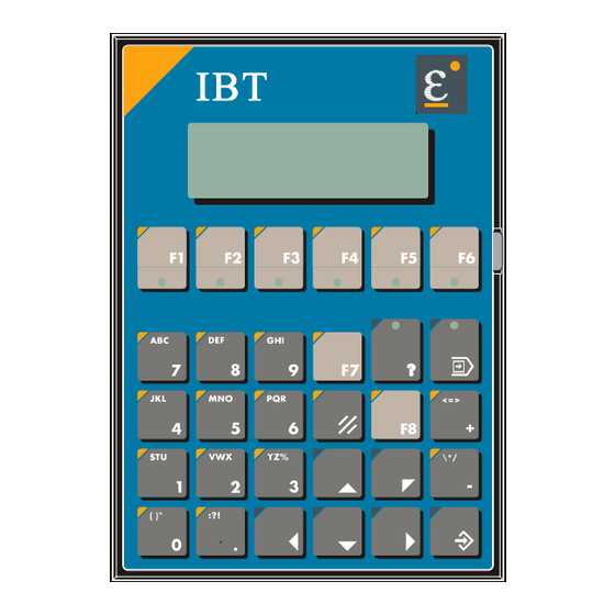
1 Allgemeines 1.1 Beschreibung Das Intelligente Bedien-Terminal IBT vereinfacht die Ein- und Ausgabe von Prozeßgrößen für den Anwender. Eine komfortable Bedienung wird durch die Integration des TesiMod-Bedienkonzeptes erreicht. Die Kommunikation zwischen dem IBT und dem Regler erfolgt über die CAN - Schnittstelle. 1.2 Benötigte Komponenten 1.2.1 Hardware Numerierung... -
Page 7: Servoregler 630 - Serie
Sind das IBT und der Servoregler im Auslieferzustand sollten nach dem Einschalten der Geräte (24V- Spannungsversorgung) auf dem IBT folgende Bildschirme nacheinander sichtbar werden: Fremd-Produkte Eurotherm-Produkte Regler 635 IBT-Rückseite AC Mn 1.3.2 Servoregler 630 - Serie Der Servoregler muß in der Betriebsart 5 „Lageregelung mit BIAS-Abarbeitung“ arbeiten. Die Konfiguration und Parametrierung des Verstärkers erlaubt den Betrieb mit dem angeschlossenen Motor (ohne Mechanik). -
Page 8: Die Erste Applikation
2 Die erste Applikation Um Ihnen die Arbeit zu erleichtern, haben wir auf der Demodiskette eine erste Applikation für Sie vorbereitet. Um die Applikation abarbeiten zu können müssen Sie Einstellungen am Servoregler und am IBT vornehmen. 2.1 Notwendige Arbeiten auf dem Servoregler Alle nun folgenden Arbeiten werden mit der Programmier- und Diagnoseoberfläche EASYRider über die serielle Verbindung zum Servoregler ausgeführt. -
Page 9: Laden Des Bias-Programms
2.1.2 Laden des BIAS-Programms • Wechseln Sie in den BIAS-Editor („BIAS“, „BIAS-Editor“). • Laden Sie das BIAS-Programm „Demo_1D.ASB“ aus dem Projektverzeichnis (Menü „Datei“, „BIAS-Programm laden“ oder Taste „F2“). • Übertragen Sie dieses Programm an den Verstärker (Menü „Programm“, „BIAS-Programm senden“ oder Taste „F4“). •... -
Page 10: Aktivieren Des Downloadmodus
Überprüfen Sie die verwendete serielle Schnittstelle unter "Bearbeiten“, „COMx-Schnittstelle“ (Auswahl mit der Leertaste und anschließender Betätigung der Enter-Taste). Aktivieren Sie den Downloadmodus des IBT (siehe Kapitel 2.2.2). Starten Sie die Downloadfunktion mit der Taste F6. 2.2.2 Aktivieren des Downloadmodus Der Downloadmodus des IBT-Bedienfeldes ist die Voraussetzung zum Laden eines Projektes. Es gibt zwei grundsätzliche Wege das Bedienfeld in den Download-Modus zu schalten. - Page 11 2.2.2.2 Aktivieren des Downloadmodus über die Setup-Maske Im Gegensatz zur ersten Möglichkeit ist es bei dieser zweiten Möglichkeit erforderlich, daß bereits ein Projekt geladen wurde und in der Setup-Maske eine entsprechende Möglichkeit programmiert wurde. Um in die Setup-Maske zu gelangen, müssen Sie während der Anzeige der Startmaske ( für ca.
-
Page 12: Beschreibung Des Demoprojektes
3 Beschreibung des Demoprojektes Die hier dargestellten Flußpläne geben den Ablauf des Demoprojektes wieder. 24 V Einrichten einschalten V ist 0 U/Min Istpos. 1000 Fahre INITIALIZING Ende CPU 10 MHz Fahre negativ Fahre positiv so lange gedrückt so lange gedrückt Eurotherm Antriebe Eurotherm Antriebe Im Sand 14... -
Page 13: Hinweise Zur Fehlersuche
4 Hinweise zur Fehlersuche 4.1 Kommunikationsfehler Wird nach der Anzeige der IBT-Startmaske bzw. während des Betriebs eine Fehlermaske (z.B. ) angezeigt, können Sie die Fehlerursache anhand des angezeigten Code und Subcode feststellen. Fehlermeldungen mit dem Code 50 deuten dabei auf eine fehlerhafte Verdrahtung bzw. fehlerhafte Parametrierung des IBT bzw. -
Page 14: Funktionsfehler
4.2 Funktionsfehler Sollte die Applikation entsprechend der Beschreibung im Kapitel 3 abgearbeitet werden (Bildschirme werden ordnungsgemäß angezeigt, der Wechsel zwischen den Bildschirmen ist wie beschrieben möglich) aber sich der Motor nicht bewegen liegt das Problem wahrscheinlich in der BIAS- Abarbeitung des Servoreglers. Um die Ursache zu finden überprüfen Sie bitte in der Reglerdiagnose des Servoreglers folgende Punkte: ... -
Page 15: Anschlußbelegung
5 Anschlußbelegung 5.1 Schirmung Die Schirmung sollte beidseitig an einem metallisierten Steckergehäuse angeschlossen sein. Durch die beidseitige Erdung ist jedoch darauf zu achten, daß ggf. eine Potential- Ausgleichsleitung mit mind. 10-fachen Querschnitt des Schirms erforderlich ist. (wegen Erdpotentialverschiebungen - damit keine Ausgleichsströme über den Schirm fließen, besonders dann, wenn Steuerung und Terminal nicht den gleichen Massepunkt haben.) 5.2 Schnittstellen... -
Page 16: Pin-Belegung Can-Schnittstelle Ibt Und Servo
5.2.2 Pin-Belegung CAN-Schnittstelle IBT und Servo Funktion Bezeichnung CAN_L Leitung CAN_L (dominant low) Masse CAN_GND Masse CAN_GND CAN_H Leitung CAN_H (dominant high) Die Schirmung des Kabels ist mit dem Steckergehäuse zu verbinden ! Für die Kommunikation muß auf dem Bus ein definierter Ruhepegel gewährleistet werden. Dazu müssen an beiden Strangenden Abschlußwiderstände zugeschaltet werden. -
Page 17: Index
6 Index Beispiel Ablauf ............12 Betriebsart Automatik........12 Betriebsart Einrichten ........12 Benötigte Komponenten........6 BIAS-Programm laden ........9 Busstecker ............16 CAN-Bus Einstellungen ........8 CAN-Bus-Kabel ..........16 Downloadmodus aktivieren......10 Fehlersuche.............13 Funktionsfehler..........14 CAN-Bus-Kabel ........16 DIP-Schalter ..........7 Downloadmodus aktivieren .......10 Fehlermaske..........13 Programmierkabel........16 Projekt laden ..........9 Spannungsversorgungskabel......15 Vorbereitung ..........9 Kabel ..............6 Versorgungsspannung........15 Programmierkabel ..........16... -
Page 18: General
1 General 1.1 Description The intelligent operator terminal IBT facilitates the input and output of process variables for the user. Convenient operating is achieved through the integration of the TesiMod operating concept Communication between the IBT and the controller is done over the CAN interface. 1.2 Required Components 1.2.1 Hardware Numbering... -
Page 19: Servo Drive 630 Series
If the IBT and the servo drive in the delivery status the following screens should be visible in sequence on the IBT after switching on (24V-power supply). External products Eurotherm products Drive 635 IBT-rear side AC Mn 1.3.2 Servo drive 630 series The servo drive must operate in the operation mode 5 “Position control with BIAS execution”. -
Page 20: The First Application
2 The first application In order to facilitate your work we prepared an first application on the demo disc for you. In order to be able to execute the application you must carry out adjustments on the servo drive and on the IBT. -
Page 21: Load Bias-Program
2.1.2 Load BIAS-Program • Please change to the BIAS editor (“BIAS“, “BIAS Editor“). • Please load the BIAS-program “Demo_1E.ASB“ from the project directory (menu “file“, “load BIAS-program“ or key “F2“). • Please transmit this program to the drive (menu “program“, “transmit BIAS-program“ or key “F4“). -
Page 22: Activate The Download Mode
Please check the used serial interface with “Edit”, “interface COMx” (selection with the space bar and following Enter key). Please activate the download mode of the IBT (see Cap. 2.2.2.). Please start the download with the key F6. 2.2.2 Activate the download mode The download mode of the IBT operator terminal is the precondition for loading a project. - Page 23 2.2.2.2 Activate the download mode via the Setup mask In contrast to the first possibility it is necessary with this second possibility that a project was already loaded and an appropriate possibility was programmed in the setup mask. In order to enter the setup mask, you must have pressed the key "Enter" ( ) during the display of the starting mask ( for approx.
-
Page 24: Description Of The Demo Project
3 Description of the Demo project The flow charts represented here show the flow of the demo project. switch on Setup 24 V act. speed 0 U/rpm act. pos. 1000 Move INITIALIZING CPU 10 MHz Move negative Move positive as long as pressed as long as pressed Eurotherm Antrieb Eurotherm Antriebe... -
Page 25: Troubleshooting
4 Troubleshooting 4.1 Communication errors If an error mask (i.e. ) is displayed after the IBT starting mask, or during operation, you can detect the error cause by the error code and sub-code. Error masks with the code 50 indicate an incorrect wiring and/ or an erroneous parameterisation of the IBT and/ or the servo drive. -
Page 26: Operational Errors
4.2 Operational errors If the application should be processed according to the description in chapter 3 (The masks are correctly displayed, the change between the masks is possible as described), but not move the motor, the problem is probably situated in the BIAS processing of the servo amplifier. To find the cause you please check the following points in the amplifier diagnosis of the servo amplifier: ... -
Page 27: Connector Pin Assignment
5 Connector pin assignment 5.1 Shielding Shielding should be connected on both sides to a metallised plug housing. Through the grounding on both sides you must, however, observe that, should it be necessary, a potential compensation line with at least 10 times the cross section of the shield is required (earth potential shift - so that no compensation currents flow over the shield, especially when the controller and terminal do not have the same ground point). -
Page 28: Pin Assignment X2.1/2 Can Interface Ibt And Servo
5.2.2 Pin assignment X2.1/2 CAN interface IBT and Servo Function Designation CAN_L bus line CAN_L (dominant low) Ground CAN_GND Ground CAN_GND CAN_H bus line CAN_H (dominant high) The shielding of the cable is to be connected with the plug housing! A defined quiescence level on the bus must be guaranteed for communication. -
Page 29: Index
6 Index activate Download mode ........22 bus plugs............28 Cable ..............18 supply voltage ..........27 CAN-Bus Adjustments ........20 CAN-Bus-Cable..........28 Example course............24 Hardware ............18 activate Download mode ......22 CAN-Bus-Cable .........28 DIP-Switch..........19 Error mask..........25 Load project..........21 Preparation..........21 Programming cable ........28 supply voltage cable ........27 Load BIAS-Program........21 Load project ...........21 Operational errors .........26... - Page 30 7 Änderungsliste Modification record Version Änderungsgrund Modification Kapitel Datum Name Bemerkung Chapter Date Name Comment V02.24TB99 Ur-Version Source version 18.06.99 T. Beul im Eurotherm-Format in Eurotherm design Erstinbetriebnahme Typ: IBT V02.24TB99 (UL: 9.5.2) Getting Started Model: IBT V02.24TB99 (UL: 9.5.2)
Need help?
Do you have a question about the IBT Series and is the answer not in the manual?
Questions and answers