Advertisement
Quick Links
Advertisement

Related Manuals for Everlasting KING TROLLEY 20 L


Summary of Contents for Everlasting KING TROLLEY 20 L
- Page 1 Use and maintenance manual BLAST CHILLERS/SHOCK FREEZERS KING TROLLEY Rev.7-7...
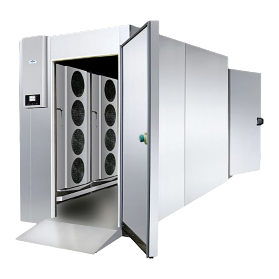
- Page 2 Blast chilling Rapid freezing Model +90°C / +3°C +90°C / -18°C KING TROLLEY 20 L / P 80 Kg. / 110 Kg. 60 Kg. / 85 Kg. KING TROLLEY 40 L / P 150 Kg. / 220 Kg. 120 Kg. / 170 Kg.
- Page 3 Load capacity 2 x 20 GN 1/1 1 x 20 EN 60x40 KING TROLLEY 20 L 1 / P 1 1 x 20 GN 2/1 1 x 20 EN 60x80 2 x 20 GN 1/1...
-
Page 4: Chapter 2 Cleaning The Refrigerator
ENGLISH 1.1 It is prohibited to remove the guards and safety devices t is absolutely forbidden to remove safety guards. The manufacturer disclaims any liability for accidents due to failure to comply with this obligation. 1.2 Information on emergency operations in the event of fire - disconnect the blast chiller from the electrical outlet or cut off the main power supply - do not use water jets - use dry chemical or CO2 extinguishers... - Page 5 ENGLISH CHAPTER 3 PERIODIC CHECKS TO BE CARRIED OUT The following are the points or units of the blast chiller that require periodic checks: - integrity and efficiency of door seals - integrity of the grilles in contact with food - integrity of the fixing hinges of the doors - integrity of the power cord of the blast chiller and the remote motocondensing unit 3.1 PRECAUTIONS IN CASE OF LONG PERIODS OF INACTIVITY...
- Page 6 ENGLISH CHAPTER 6 TROUBLESHOOTING Problems may occur, in the blast chiller, identified as shown in the table: TROUBLE DESCRIPTION POSSIBLE CAUSES HOW TO REPAIR IT the blast chiller does not turn on no power supply check the plug, socket, fuses, line other fuses, line the refrigeration unit does not start...
- Page 7 ENGLISH The following are the measures taken to protect against other risks: - electricity: The blast chiller has been designed, built and equipped so as to prevent risks from electricity, in accordance with the specific legislation in force - noise: The blast chiller has been designed and built in such a way that risks resulting from the emission of airborne noise are reduced to the minimum level 8.1 safety devices adopted It is absolutely forbidden (Fig.
- Page 8 ENGLISH Right load of the blast chiller Avoid overloading the blast chiller beyond the set limits shown in the table Do not place the trays too close to each other so as to avoid uneven air circulation inside the blast chiller Do not place the trays too far away from the evaporator Do not concentrate the trays in one area of the blast chiller in case the load is not complete;...
-
Page 9: Chapter 9 Controls
ENGLISH CHAPTER 9 CONTROLS 9.1 Description of the controls and buttons (Fig. 3) Fig.3 The control buttons with which the blast chiller is equipped are: On / off push-button, “ON / OFF” Option push-button, “MENÙ push-button” Preset push-button, “HOME push-button” Cancel push-button, “ESC push-button”... - Page 10 ENGLISH 9.2 INSTRUCTIONS FOR USE 9.2.1 Starting Before starting the temperature blast chiller you need to check if electrical and power connections have been carried out according to what stated at Chapter 17. LOADING... Connect the machine to power supply: the display is turned off for 10 seconds then it will ►...
- Page 11 ENGLISH In the “ON” and “STAND-BY” modes the control panel will ► show date, real time and cell temperature. In the “RUN” mode the display will show what follows: ► - if a temperature cooling or freezing process is currently un- der process, the temperature taken by the core probe, the cell temperature, the name of the program (if any) and the time Program: MANUAL...
- Page 12 ENGLISH To set current date proceed as follows: 22/12/08 18:15 Press and release the key or the key to modify the day. ► Press and release the key to confirm the data entered, ► Once the date has been set, the control panel will automatically set current year, hours and ►...
- Page 13 ENGLISH Press and release the ESC key to exit from the above procedure. 9.2.4 Operation The temperature blast chiller is able to manage the following types of operating cycles: Positive Temperature Cooling with core probe (Par. 9.2.5) ► Hard Positive Temperature Cooling with core probe (Par. 9.2.6) ►...
- Page 14 ENGLISH 9.2.5 Positive Temperature Cooling with core probe TheTemperature Cooling and preservation cycle consists of the following two phases: Cooling ► Preservation ► When a phase is over the control panel automatically switches to the next step. To start a cycle proceed as follows: Press and release the key (1), ►...
- Page 15 ENGLISH If the temperature taken by the core probe reaches the end-of-cooling temperature within the coo- ► ling phase time limit , the cooling will be successfully completed, the control panel will automatically switch to the preservation phase and the buzzer will sound. To silence buzzer press and release any key.
- Page 16 ENGLISH 9.2.6 Hard Positive Temperature cooling with core probe The temperature hard cooling and preservation cycle consists of the following three phases: Cooling hard phase ► Cooling ► Preservation ► When a phase is over the control panel automatically switches to the next step. To start the cycle proceed as follows: - Make sure the display is in the “ON”...
- Page 17 ENGLISH When the temperature taken by the core probe reaches the end-of-hard-cooling phase the control panel will automatically switch to the cooling phase. During the cooling phase, the display will show the temperature taken by the core probe, the cell temperature, the name of the program (if any) and the time elapsed since the starting of the cooling process.
- Page 18 ENGLISH Press and release the key (1), then press and ► release the key (2): The display will show the cooling duration and the run- ning temperature during the cooling process Press and release the MENU key, then press and release key or the key key to select ►...
- Page 19 ENGLISH When a phase is over the control panel automatically switches to the next step. To start the cycle proceed as follows: Make sure the display is in the “ON” mode. ► Make sure the keyboard is not locked and no procedu- ►...
- Page 20 ENGLISH 9.2.9 Positive Temperature Continuous Cooling To start the cycle proceed as follows: Make sure the display is in the “ON” mode. ► Make sure the keyboard is not locked and no procedu- ► re is currently under process. Press and release the (1) key, press and re- ►...
- Page 21 ENGLISH 9.2.10 Freezing with core probe The temperature freezing and preservation cycle consists of the following two phases: Freezing ► Preservation. ► When a phase is over the control panel automatically switches to the next step. To start the cycle proceed as follows: Make sure the display is in the “ON”...
- Page 22 ENGLISH During the freezing process the display will show the temperature taken by the core probe, the ► cell temperature, the name of the program (if any) and the time elapsed since the starting of free- zing process. Hold the START/STOP key pressed for 3 seconds to stop the cycle. ►...
- Page 23 ENGLISH Make sure the display is in the “ON” mode. ► Make sure the keyboard is not locked and no procedu- ► re is currently under process. ► Press and release the (1) key, press and rele- (2) key, then press and release (3) key : in oder the icon “core probe”...
- Page 24 ENGLISH During the preservation phase the display will show ► the cell temperature, the name of the program (if any) and the time taken to complete the freezing successfully. Program: MANUAL Cycle time: 220 min If the temperature taken by the core probe does not reach the end-of-freezing temperature ►...
- Page 25 ENGLISH The display will show the duration of the freezing phase and the running setpoint during the free- zing process. Press and release the MENU key, then press and release the key or the key key to ► select the duration of the freezing phase running setpoint during the freezing process, other than the set one.
- Page 26 ENGLISH Make sure the display is in the “ON” mode. ► Make sure the keyboard is not locked and no procedu- ► re is currently under process. Press and release the (1) key, then press ► and release the (2) key: the display will show the duration of the freezing phase and the operating setpoint during the freezing process.
- Page 27 ENGLISH 9.2.14 Continuous Hard Freezing To start the cycle proceed as follows: Make sure the display is in the “ON” mode. ► Make sure the keyboard is not locked and no procedu- ► re is currently under process. Press and release the (1), press and release ►...
- Page 28 ENGLISH 9.2.16 Test for checking the core probe proper insertion Temperature cycles are preceeded by a two-phase test to check if the core probe has been properly inserted. The second phase will be carried out only if the first one has not been successfully completed. If the test has been successfully completed the cycle starts otherwise the buzzer will be sounding for 5 seconds every 60 seconds and a time cycle will start.
- Page 29 ENGLISH Make sure the display is in the “ON” mode. ► Make sure the keyboard is not locked and no procedu- ► FISH SANIFICATION re is currently under process. Press and release the (1) key, then press and ► release (2) key: The display will show the end-of-cooling temperature , the running temperature during the cooling process and the holding time.
- Page 30 ENGLISH 9.2.19 Defrosting the device Defrosting is carried out automatically on Trolley blast chiller, only if the evaporator temperature re- quires it at the end of each chilling or freezing cycle, and every 8 hours during storage cycle. It is possible to activate a manual defrosting as follows: Make sure the device is “on”...
- Page 31 ENGLISH CAPITOLO 10 PROGRAMS Introduction The “Program” function allows you to save settings in a program and start a running cycle using the settings previously saved by Users . It is possible to save up to 99 programs. 10.1 Saving a program After selecting the favourite Cooling or Freezing cycle proceed as follows: Make sure the keyboard is not locked and no procedu- ►...
- Page 32 ENGLISH 10.2 Program name Proceed as follows: Press and release the (1) key or the (2) key ► to select the number of the program then press and rele- ase the (3) key to give it a name. Select letters with key then confirm with key.
-
Page 33: Chapter 11 "Favourite" Function
ENGLISH CHAPTER 11 “FAVOURITE” FUNCTION Introduction : The “Favourite” function allows you to call up and carry out programs recently performed. It is possibe to start up to 99 recent programs. 11.1 1 Implementation of a program in the “FAVOURITE” list Proceed as follows : - Make sure the control panel is in the “ON”... - Page 34 ENGLISH 12.1 HACCP alarms information display Proceed as follows: Make sure the control panel is in the “ON” mode. ► OPTIONS Make sure the keyboard is not locked and no procedure ► 22/12/08 18:15 HACCP ALARMS is currently under process. PARAMETERS LANGUAGE INTERNAL VALUES...
- Page 35 ENGLISH Press and release the (4) key, press and release ► CLEAR HACCP (5) key or the (6) key to select the alarm, then press and release the (7) key. Repeatedly press and release key to set “149” then press and release key ►...
- Page 36 ENGLISH CHAPTER 13 ALARMS This table shows you the alarms which may occur ALARM DESCRIPTION CAUSE HOW TO SOLVE Cell probe error • Cell probe is faulty • Substitute probe Evaporator probe error • Evaporator probe is faulty • Substitute probe Condenser probe error •...
- Page 37 ENGLISH CAPITOLO 14 USB DOOR ATTENTION: by inserting a USB key you may have the possibility to carry out the following functions: Download data relative to performed cycles to USB key (historical records) ► Download the saved parameters to USB key (service) ►...
-
Page 38: Chapter 15 Noise Level
ENGLISH The recorded data file have a sequential number according to the number of downloads. In this way the name of the file may vary from “log00n00001.csv” to “log00n00002.csv” and so on. All the acquired data will be automatically reported in an Excel table , separated in columns and lines, thus allowing to draw tables and charts (see the example) according to your requirements. -
Page 39: Chapter 17 Transport And Handling
ENGLISH To prevent potential negative consequences for the environment and human health, make sure that this product is properly disposed of and recycled. For more information regarding the disposal and recycling of this product, please contact your Distributor, after sale Service, or waste treatment Service. CHAPTER 17 TRANSPORT AND HANDLING The transport and handling of the blast chiller must only be done while maintaining the vertical position, observing the markings on the packaging. - Page 40 ENGLISH use protective gloves when handling the wooden packaging and the wooden base. The presence of splinters may cause damage to your hands - remove the PVC film applied as a protection to the outer surfaces of the blast chiller - position the blast chiller using a level (Fig.
- Page 41 ENGLISH CHAPTER 18 ELECTRICAL WIRING AND CONNECTIONS The electrical system and connection must be carried out by qualified personnel. Before installation, measure the impedance of the network, the impedance value for the connection to the network must not exceed 0.075 ohm. For safety reasons you must follow these guidelines: - verify that the sizing of the electrical system is suitable for the power consumption of the blast chiller and that it provides for a differential switch (circuit breaker)
- Page 42 ENGLISH ATTENTION! INSTRUCTIONS RESERVED SOLELY TO TECHNICAL PERSONNELL Users are adviced that any work performed by non-technical staff or unauthorized personnel will produce the voiding of the warranty rules.
- Page 43 ENGLISH SETTING OF CONFIGURATION PARAMETERS Proceed as follows: Make sure the control panel is in the “ON” mode. ► OPTIONS Make sure the keyboard is not locked and no procedure ► 22/12/08 18:15 HACCP ALARMS is currently under process. PARAMETERS LANGUAGE INTERNAL VALUES ALARMS LIST...
- Page 44 ENGLISH Number of sensors of core probe core probe not enabled - - - - 1 = 1 (core probe1) 2 = 2 (core probe 1 and core probe 2) 3 = 3 (core probe 1, core probe 2 and core probe 3) Enable the evaporator probe - - - - 1 = yes...
- Page 45 ENGLISH minimum time interval between the switching off of compressor and the following switching on (3) Minimum duration of the compressor switching on Duration of the compressor switching off during cell probe error (code “Pr1”) occurring during preservation; see also the C5 and C9 parameters Duration of the compressor switching on during cell probe error (code “Pr1”) occurring during preservation after cooling ;...
- Page 46 ENGLISH Enable maximum temperature alarm (code “AH”) - - - - 1 = yes Delayed temperature alarm (code “AL” and code “AH”) Delayed maximum temperature alarm (code “AH”) from the end of evaporator fan stop and from the preservation starting duration of power supply interruption such to cause the storage of the power supply failure alarm (code “PF”) when it is reset 0 = alarm will not be signalled...
- Page 47 ENGLISH Speed 3 of the evaporator fan (in terms of percentage of maximum speed: if the F0 parameter is set to 3 only); see paragraph 6.12 “cooling and freezing intensity” Speed 4 of the evaporator fan (in terms of percentage of maximum speed;...
- Page 48 ENGLISH Delayed low pressure alarm signal (code “LP”) -1 =alarm is not reported iType of contact on the compressor thermal protection input - - - - 0 =normally open (active input with closed contact) 1 =normally closed (active input with open contact) Delayed compressor thermal protection alarm signal (code“CtH”) -1 =alarm is not reported - - - -...
-
Page 49: Alarm List
ENGLISH ALARM LIST DISPLAYING Display the alarms and troubleshooting Press key MENU (2), ► Select by keys UP-DOWN (9-10) and ALARM ► LIST and press key SET (11) (11) OPTION 22/12/08 18:15 HACCP ALARM (10) PARAMETERS LANGUAGE INTERNAL VALUES ALARM LIST Press keys UP-DOWN (9-10) to scroll the ►... - Page 50 ENGLISH INTERNAL VALUES DISPLAYING This page will show you all the internal values. Internal values term refers to the temperature values and the appliance active relays that cannot be modified. Press key MENU (2), ► Select with the UP-DOWN keys (9-10) the ►...
-
Page 51: Historical Data
ENGLISH DI HP • Disabled DI LP • Disabled DI CTH • Disabled DO Comp • Compressor digital output DO Fan Evap • Evaportaor fan digital output DO Fan Cond • Disabled DO Risc Door • Door resistance digital output DO Risc Core •... - Page 52 ENGLISH DOWNLOAD OF SAVED PROGRAMS ON A USB STICK When it is ON switch the card on OFF mode ► by pressing the ON/OFF key (1) DOWNLOAD ALL RECORDED DATA DOWNLOAD PARAMETERS Insert the USB stick in the USB port. ►...
- Page 53 ENGLISH UPLOAD OF SAVED PROGRAMS When it is ON switch the card on OFF mode ► by pressing the ON/OFF key (1) DOWNLOAD ALL RECORDED DATA Insert the USB stick containing the DOWNLOAD PARAMETERS ► DOWNLOAD PROGRAMS parameters in the USB port. UPLOAD PARAMETERS UPLOAD PROGRAMS Select with the UP-DOWN keys (9-10) the...
- Page 54 ENGLISH LEGENDA: M1: terminal board 1 for the connection to the condensing unit EVFTFT818 M2: terminal board 2 for the connection to the cell loads PRB1: cell probe Interfaccia utente porta USB PRB2: evaporator probe PRB3: core probe UV: sterilising lamp (optional) AL: alarm device by customer MP: micro door KV: evaorator fan relay...
- Page 55 ENGLISH MODELL TABELLA 1 Ingombri del armadio Peso peso del materiale Volume Potenze TABLE 1 imballato netto imballato depos. Powers Dimensions of the shipping weight Depos. packed cabinet weight volume cartone Potenza frig. Assorb. c.board Refrig. power Absorption T. evap. -20° +55°...
- Page 56 ENGLISH EVERLASTING s.r.l. 46029 SUZZARA (MN) - ITALY - Strada Nazionale della Cisa km.161 Tel.0376/521800 (4 linee r.a.) - Telefax 0376/521794 http://www.everlasting.it - E-mail:everlasting@everlasting.it...
Need help?
Do you have a question about the KING TROLLEY 20 L and is the answer not in the manual?
Questions and answers