Hydac HDA 5500 Series User Manual
Digital display unit for oil condition sensor hydaclab hlb1000 and contamination sensor cs1000
Hide thumbs
Also See for HDA 5500 Series:
- User manual (55 pages) ,
- User manual (68 pages) ,
- User manual (68 pages)
Table of Contents
Advertisement
Available languages
Available languages
Quick Links
Digitales Anzeigegerät HDA 5500
für Ölzustandssensor HYDACLab
und Contamination Sensor CS1000
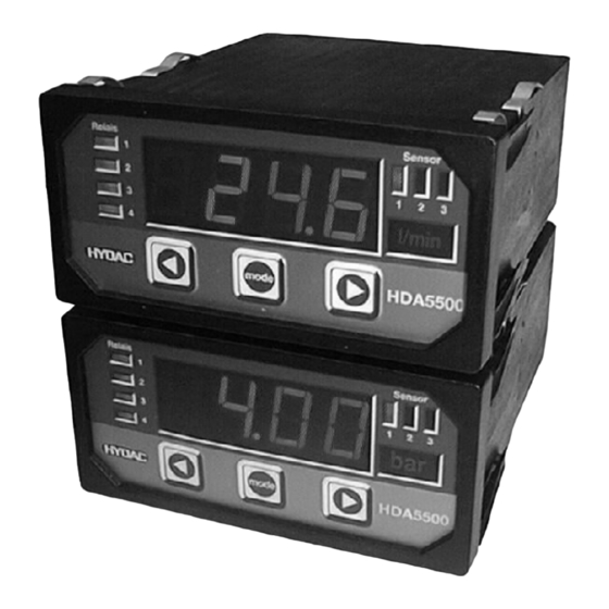
Digital Display Unit HDA 5500
for Oil Condition Sensor HYDACLab
and Contamination Sensor CS1000
Afficheur digital HDA 5500 pour capteur
d'état de l'huile HYDACLab
et de pollution CS1000
Benutzerhandbuch
User Manual
Notice d'utilisation
HDA 5500-0-2-AC-006 (CM1k)
HDA 5500-0-2-DC-006 (CM1k)
Stand:
25.06.2008
Mat..-Nr.
669731
®
HLB 1000
®
®
HLB1000
HLB1000
Advertisement
Chapters
Table of Contents

Related Manuals for Hydac HDA 5500 Series


Summary of Contents for Hydac HDA 5500 Series
- Page 1 Digitales Anzeigegerät HDA 5500 ® für Ölzustandssensor HYDACLab HLB 1000 und Contamination Sensor CS1000 Digital Display Unit HDA 5500 ® for Oil Condition Sensor HYDACLab HLB1000 and Contamination Sensor CS1000 Afficheur digital HDA 5500 pour capteur ® d’état de l'huile HYDACLab HLB1000 et de pollution CS1000 Benutzerhandbuch...
- Page 2 HDA 5500 für HLB1000 und CS1000...
-
Page 3: Table Of Contents
Anschluss von bis zu vier Schaltausgängen 11 Einstellen von Schaltpunkten und Hysteresen 11.1 Schaltausgänge 11.2 Schaltfenster 12 Programmierfreigaben 12.1 Änderung der Betriebsprogrammierfreigabe 12.2 Änderung der Hauptprogrammierfreigabe 13 Technische Daten 14 Typenschlüssel HDA 5500 15 Geräteabmessungen 16 Pinbelegung 17 Fehlermeldungen 18 HYDAC Service - 2 -... -
Page 4: Einleitung
Die Anzeigegeräte der Serie HDA 5500 sind wartungsfrei und arbeiten beim Einsatz inner- halb spezifizierter Bedingungen einwandfrei. Treten dennoch Fehler auf, so wenden Sie sich bitte an den HYDAC-Service. Nicht vorschriftsgemäße Montage oder Fremdeingriffe in das Gerät führen zum Erlöschen jeglicher Gewährleistungsansprüche. -
Page 5: Bedienelemente
HDA 5500 für HLB1000 und CS1000 4 Bedienelemente 4-stellige Digitalanzeige LED-Anzeigen aktiver LED-Anzeigen Schaltpunkte aktiver Sensor Sensor Relais 1 2 3 HDA5500 MODE MODE Anzeige der Einheit von Sensor 1, 2, 3 oder 4 Tasten zur Einstellung der Schaltpunkte, Rückschaltpunkte und der Menüfunktionen 5 Auswahl und Darstellung der Messeinheit Die Einheit, welche dem Wert in der Anzeige zugeordnet ist, wird vom Bediener anhand... -
Page 6: Montage Und Inbetriebnahme
HDA 5500 für HLB1000 und CS1000 6 Montage und Inbetriebnahme 6.1 Mechanischer Einbau Das HDA 5500 ist ein Schalttafeleinbaugerät mit einem Normeinbaugehäuse 96 x 48 mm und benötigt einen Schalttafelausschnitt von 92 x 45 mm. Schalttafeldicke: mindestens 1,25 mm Einbautiefe: mindestens 150 mm Panel-Clips Spannführungen 6.2 Elektrischer Anschluss... -
Page 7: Versorgungsspannung
HDA 5500 für HLB1000 und CS1000 6.3 Versorgungsspannung Die Versorgungsspannung wird an Klemmleiste X1 angeschlossen. 12..32 VDC HDA 5500–0–2–DC–XXX (siehe Typenschild) 85..265 VAC 50 / 60 Hz HDA 5500–0–2–AC–XXX (siehe Typenschild) Nach Einschalten der Versorgungsspannung wird für ca. 2 s HdA angezeigt. Dann wird die Bezeichnung des Sensors angezeigt, dessen Wert als Primäranzeige eingestellt ist. -
Page 8: Programmierung
HDA 5500 für HLB1000 und CS1000 7 Programmierung Zur Anpassung an die jeweilige Applikation wird das HDA 5500 mittels Variation der Grund- einstellungen programmiert. Die Grundeinstellungen sind in einem Menü zusammengefasst. Achtung: Bei aktiviertem Menü werden keine Schaltfunktionen ausgeführt. 7.1 Einstellung der Grundeinstellungen Um die Grundeinstellungen zu ändern, ist das Menü... -
Page 9: Übersicht Menü Der Grundeinstellungen
HDA 5500 für HLB1000 und CS1000 7.2 Übersicht Menü der Grundeinstellungen Menüpunkt Einstellung Einstellbereich Voreinstellung Device: HLB, Geräte auswahl zur Messwertanzeige des angeschlossenen HLB 1000 Geräte auswahl zur Messwertanzeige des angeschlossenen CS 1000 Bei Geräteauswahl HLB 1000 Zuordnung Schaltausgang 1 (S.S.1) r.ViS. - Page 10 HDA 5500 für HLB1000 und CS1000 Menüpunkt Einstellung Einstellbereich Voreinstellung Schaltfunktion Schaltausgang 3 (S.S.3) r.ViS. r.ViS. r.diE. Analog zu Schaltausgang 1 (s. o.), d. h. im weiteren: r.HuM. • Schaltfunktion (S.M.3) TEMP. • Schaltrichtung (S.d.3) • Einschaltverzögerung (T.on.3) • Abschaltverzögerung (T.oF.3) 0..99.99 s 0..99.99 s Schaltfunktion Schaltausgang 4 (S.S.4)
- Page 11 HDA 5500 für HLB1000 und CS1000 Menüpunkt Einstellung Einstellbereich Voreinstellung Dezimalstelle für Anzeige der rel. Viskositätsänderung (dEc.V.) 0 .. 0.000 Dezimalstelle/n des angezeigten Messwertes der rel. Viskositätsänderung Unterer Grenzwert der rel. Viskositätsänderung (LOr.V.) -999..9899 -30.0 Unterer Grenzwert des Anzeigebereichs der rel. Viskositätsänderung Oberer Grenzwert der rel.
- Page 12 HDA 5500 für HLB1000 und CS1000 Menüpunkt Einstellung Einstellbereich Voreinstellung Dezimalstelle für Anzeige der Temperatur (dEc.T.) 0 .. 0.000 Dezimalstelle/n des angezeigten Messwertes der Temperatur Unterer Grenzwert der Temperatur (LOr.T.) -999..9899 -25.0 Unterer Grenzwert des Anzeigebereichs der Temperatur Oberer Grenzwert der Temperatur (Hir.T.) -899..9999 100.0 Oberer Grenzwert des Anzeigebereichs...
- Page 13 HDA 5500 für HLB1000 und CS1000 Menüpunkt Einstellung Einstellbereich Voreinstellung Bei Geräteauswahl CS 1000 Achtung: Die Voreinstellungen der unteren und oberen Grenzwerte von Kanal 1 bis 4 (LO.1 bis LO.4 und Hi.1 bis HI.4) entsprechen den Werten bei Betrieb des HLB 1000 am HDA 5500. Bei Betrieb des CS1000 am HDA5500 ist zu beachten: Für die im CS 1000 eingestellten analogen Signalausgangsformen HDA.ISO, HDA.SAE oder HDA.NAS müssen die Vorein- stellbereiche wie folgt umgestellt werden.
- Page 14 HDA 5500 für HLB1000 und CS1000 Menüpunkt Einstellung Einstellbereich Voreinstellung Schaltfunktion Schaltausgang 2 (S.S.2) Kanal 1 Kanal 1 Kanal 2 Analog zu Schaltausgang 1 (s. o.), d. h. im weiteren: Kanal 3 • Schaltfunktion (S.M.2) Kanal 4 • Schaltrichtung (S.d.2) •...
- Page 15 HDA 5500 für HLB1000 und CS1000 Menüpunkt Einstellung Einstellbereich Voreinstellung Primäranzeige (PriM) Wert, der permanent im Display angezeigt wird: Kanal 1 Kanal 1 Kanal 2 Messwert von Kanal 1 Kanal 3 Kanal 4 Minimalwert von Kanal 1 Spitzenwert von Kanal 1 Kanal 1 Kanal 2 Messwert von Kanal 2...
- Page 16 HDA 5500 für HLB1000 und CS1000 Menüpunkt Einstellung Einstellbereich Voreinstellung Hintergrundbeleuchtung der Einheit von Kanal 1(uni.1.) Hintergrundbeleuchtung ein Hintergrundbeleuchtung aus Dezimalstelle für Anzeige von Kanal 2 (dEc.2.) 0 .. 0.000 Dezimalstelle/n des angezeigten Messwertes von Kanal 2 Unterer Grenzwert von Kanal 2 (LO.2.) -999..9899 -30.0 Unterer Grenzwert des Anzeigebereichs...
- Page 17 HDA 5500 für HLB1000 und CS1000 Menüpunkt Einstellung Einstellbereich Voreinstellung Zuordnung des Analogausgangs zu Signal (ouT.S) Kanal 1 Kanal 1 Kanal 2 Kanal 3 der Analogausgang gibt das Signal Kanal 4 von Kanal 1 aus der Analogausgang gibt das Signal von Kanal 2 aus der Analogausgang gibt das Signa von Kanal 3 aus...
-
Page 18: Anschluss Des Ölzustandssensor Hlb 1000
HDA 5500 für HLB1000 und CS1000 8 Anschluss des Ölzustandssensor HLB 1000 8.1 HDA 5500 und Ölzustandssensor HLB 1000 HDA 5500-0-2-AC-006 (CM1k) X2.6 +12 V Signal 1 HLB 1000 X2.5 AGND X2.7 Signal 2 HDA 5500-0-2-DC-006 (CM1k) X1(+) 12..32VDC 12..32V X1(-) AGND Signal 1... -
Page 19: Digitalanzeige
HDA 5500 für HLB1000 und CS1000 9 Digitalanzeige 9.1 Standardanzeige In Kap. 7.2 sind die Möglichkeiten aufgezeigt, welche Werte sie als Primäranzeige auswäh- len können. Der jeweils eingestellte Wert wird permanent angezeigt. Hinweise: • ® Das Initialisieren des HYDACLab kann bis zu 2 Minuten dauern; erst nach Abschluss der Initialisierung sind die angezeigten Messwerte aussagekräftig. -
Page 20: Sequentieller Analogausgang Des Hlb 1000
HDA 5500 für HLB1000 und CS1000 9.3 Sequentieller Analogausgang des HLB 1000 Das Analogausgangssignal der Messwerte wird wie folgt sequentiell an PIN 4 des HLB 1000 an das HDA 5500 ausgegeben. Start Start Rel. Rel. 20mA Visko Feuchte Rel. Status Temp. -
Page 21: Sequentieller Analogausgang Des Cs1000
HDA 5500 für HLB1000 und CS1000 9.4 Sequentieller Analogausgang des CS1000 Das Analogausgangssignal der Messwerte wird wie folgt sequentiell an PIN 2 des CS1000 an das HDA 5500 ausgegeben. Start Start 20mA 4µm 14µm 6µm Status 21µm Erläuterung: Ausgabe sequentieller Analogausgang: (jeweils 4..20 mA) Startsignal: 20 mA... -
Page 22: Ausgangsverhalten
HDA 5500 für HLB1000 und CS1000 10 Ausgangsverhalten Das HDA 5500 verfügt über einen Analogausgang, dessen Signal proportional zu einem Eingangssignal ist. Der Analogausgang kann jedem der Signale (rel. Viskositätsänderung, rel. Dielektrizitätszahländerung, rel. Feuchte, Temperatur bei Geräteauswahl HLB1000 sowie CH1, CH2, CH3 oder CH4 bei Geräteauswahl CS1000) zugeordnet werden. 10.1 Analogausgang Am Analogausgang steht ein 4..20 mA oder 0..10 V Signal zur Verfügung. -
Page 23: Schaltausgänge
HDA 5500 für HLB1000 und CS1000 10.2 Schaltausgänge Jeder Schaltausgang besteht aus einem Relais, dessen Schaltkontakte als Öffner oder Schließer angeschlossen werden können. Für jeden Schaltausgang können während des regulären Betriebs die folgenden Parameter eingestellt werden (siehe Kap. 7.2, Übersicht Menü... -
Page 24: Anschluss Von Bis Zu Vier Schaltausgängen
HDA 5500 für HLB1000 und CS1000 Beispiel für Schaltausgang 1 (Relais aktiviert): Messgröße Hi.1 plus 1% FS Rückschaltwert Sicherheitszone Schaltwert hi.1 Lo.1 Schaltwert Sicherheitszone Lo.1 minus 1% FS Rückschaltwert Abkürzungen: "HI 1" bis "HI 4" = High level 1 bis 4 = oberer Schaltpunkt 1 bis 4 "Lo 1"bis "Lo 4"... -
Page 25: Einstellen Von Schaltpunkten Und Hysteresen
HDA 5500 für HLB1000 und CS1000 11 Einstellen von Schaltpunkten und Hysteresen • Während des regulären Betriebs die Taste mode betätigen. • Je nach Einstellung wird dabei SP (Schaltpunkt) oder Win (Schaltfenster) angezeigt. Hinweis: Wenn mode länger als ca. 5 s festgehalten wird, dann wird das Menü der Grundeinstellun- gen aktiviert. -
Page 26: Programmierfreigaben
HDA 5500 für HLB1000 und CS1000 mode mode mode betätigen mode loslassen oder Einstellung ändern Hinweise: • Wenn beim Betätigen von oder die Anzeige Loc erscheint, dann ist keine Pro- grammierfreigabe erteilt. Zum Erteilen einer Programmierfreigabe siehe Kap. 12, Pro- grammierfreigaben. -
Page 27: Änderung Der Hauptprogrammierfreigabe
HDA 5500 für HLB1000 und CS1000 12.2 Ändern der Hauptprogrammierfreigabe Ein Ändern der Hauptprogrammierfreigabe kann nur beim Einschalten des HDA 5500 vorgenommen werden. Wenn das HDA 5500 bereits in Betrieb ist, dann ist zuerst die Ver- sorgungsspannung abzuschalten oder das HDA 5500 von der Versorgungsspannung zu trennen. -
Page 28: Technische Daten
HDA 5500 für HLB1000 und CS1000 13 Technische Daten Anzeigebereich Anzeige 4-stellige 7-Segment LED-Anzeigefeld, rot, Zeichenhöhe 14,2 mm 3 LED für aktiven Sensor, 4 LED für Schaltpunkte Anzeigebereich - 999 .. 9999 (frei einstellbar) Anzeigeeinheiten mit Hintergrund Beleuchtung °C,°F, % (gewünschte Einheit aus Folie ausschneiden und in seitliche Einschublasche schieben) Eingangsgrößen Analoge/r Signaleingang/-eingänge... -
Page 29: Typenschlüssel Hda 5500
HDA 5500 für HLB1000 und CS1000 14 Typenschlüssel HDA 5500 Bestellangaben 5 5 0 0 – 0 – 2 – X X – 0 0 6 Eingänge 0 = Ein Analogeingang Ausgänge 2 = Vier Relaisausgänge Versorgungsspannung AC = 85..265 VAC DC = 12..32 VDC Modifikation 006 = für HLB1000 und CS 1000... -
Page 30: Geräteabmessungen
HDA 5500 für HLB1000 und CS1000 15 Geräteabmessungen - 29 -... -
Page 31: Pinbelegung
HDA 5500 für HLB1000 und CS1000 16 Pinbelegung Versorgungsspannung Stecker X1 GERÄT BESCHREIBUNG Variante HDA 5500 – X – X – AC – 000 ~ / ~ Versorgungsspannungseingänge 85VAC bis 265VAC 50/60Hz Wechselstrom 1 , 2 und 3 HDA 5500 – X – X – DC – 000 + / - Versorgungsspannungseingänge 24VDC Gleichstrom 1 , 2 und 3 Signale Stecker X2... -
Page 32: Fehlermeldungen
AGND kurzgeschlossen ist. Überprüfen Sie, dass der maximale Strom den Wert von 100 mA nicht überschreitet. 18 HYDAC Service Für Fragen zu Reparaturen oder Umbauten steht Ihnen der HYDAC Service zur Verfü- gung: Vorbehaltlich technischer Änderungen HYDAC SERVICE GMBH HYDAC ELECTRONIC GMBH Hauptstr. - Page 33 Switching window 12 Programming enable 12.1 Altering the operating programming enable 12.2 Altering the main programming enable 13 Technical specifications 14 Model code HDA 5500 15 Unit dimensions 16 Electrical connections 17 Error messages 18 HYDAC Service - 2 -...
-
Page 34: Introduction
• The unit must be installed exactly according to the instructions. • Read the information on the type code label. • Fault investigation and repairs must only be carried out by HYDAC Service. • All relevant and generally recognised safety requirements must be adhered to. -
Page 35: Operating Keys
HDA 5500 for HLB 1000 and CS 1000 4 Operating keys 4-digit digital display LED display of active LED display switching points of active sensor Sensor Relais 1 2 3 HDA5500 MODE MODE Display of unit of measurement sensor 1, 2, 3 or 4 Keys for adjusting the switching points, switch-back points and... -
Page 36: Installation And Commissioning
HDA 5500 for HLB 1000 and CS 1000 6 Installation and commissioning 6.1 Mechanical installation The HDA 5500 is a control panel unit with a standard mounting housing 96 x 48 mm and requires a control panel cut-out: 92 x 45 mm •... -
Page 37: Supply Voltage
HDA 5500 for HLB 1000 and CS 1000 6.3 Supply voltage The supply voltage is connected to terminal X1. 12..32 VDC HDA 5500–0–2–DC–XXX (see type code label) 85..265 VAC 50 / 60 Hz HDA 5500–0–2–AC–XXX (see type code label) After switching on the supply voltage, the unit displays HdA for approximately 2 s. Then the number of the sensor set as the primary display is shown. -
Page 38: Programming
HDA 5500 for HLB 1000 and CS 1000 7 Programming In order to adapt the unit to a particular application, the HDA 5500 is programmed by varying the basic settings. The basic settings are combined in a menu. Important: When the menu is activated, no switching functions are carried out. 7.1 Adjusting the basic settings To change the basic settings, the menu must be activated. -
Page 39: Overview Of Basic Settings Menu
HDA 5500 for HLB 1000 and CS 1000 7.2 Overview of basic settings menu Menu point Setting Setting range Default setting Device: HLB, Device selected to display the values measured by the HLB 1000 connected Device selected to display the values measured by the CS 1000 connected When HLB 1000 is selected Allocation switching output 1 (S.S.1) - Page 40 HDA 5500 for HLB 1000 and CS 1000 Menu point Setting Setting range Default setting Switching function switching output 3 (S.S.3) r.ViS. r.ViS. r.diE. Similar to switching output 1 (see above), and likewise for: r.HuM. • Switching mode (S.M.3) TEMP. •...
- Page 41 HDA 5500 for HLB 1000 and CS 1000 Menu point Setting Setting range Default setting Decimal place for display of rel. change in viscosity (dEc.V.) 0 .. 0.000 Decimal place(s) when displaying measured values of rel. change in viscosity Lower display range of rel. change in viscosity (LOr.V.) -999..9899 -30.0 Lower limit of the display range of rel.
- Page 42 HDA 5500 for HLB 1000 and CS 1000 Menu point Setting Setting range Default setting Decimal place for display of temperature (dEc.T.) 0 .. 0.000 Decimal place(s) when displaying measured values of temperature Lower display range of temperature (LOr.T.) -999..9899 -25.0 Lower limit of the display range of temperature...
- Page 43 HDA 5500 for HLB 1000 and CS 1000 Menu point Setting Setting range Default setting When CS 1000 is selected Important: The default settings of the upper and lower limits of channels 1 to 4 (LO.1 to LO.4 and Hi.1 to HI.4) correspond to the values for operating the HLB 1000 on the HDA 5500.
- Page 44 HDA 5500 for HLB 1000 and CS 1000 Menu point Setting Setting range Default setting Allocation of switching output 2 (S.S.2) Channel 1 Channel 1 Channel 2 Similar to switching output 1 (see above), and likewise for: Channel 3 • Switching mode (S.M.2) Channel 4 •...
- Page 45 HDA 5500 for HLB 1000 and CS 1000 Menu point Setting Setting range Default setting Primary display (PriM) Value which is normally displayed: Channel 1 Channel 1 Channel 2 Measured value Channel 1 Channel 3 Channel 4 Lowest value Channel 1 Peak value Channel 1 Channel 1 Channel 2...
- Page 46 HDA 5500 for HLB 1000 and CS 1000 Menu point Setting Setting range Default setting Lower display range of channel 1 (LO.1.) -999..9899 -30.0 Lower limit of display range of channel 1 Upper display range of the channel (Hi.1.) -899..9999 30.0 Upper limit of display range of channel 1 Background lighting for the unit label for Channel 1(uni.1.)
- Page 47 HDA 5500 for HLB 1000 and CS 1000 Menu point Setting Setting range Default setting Upper display range of temperature (Hi.4.) -899..9999 100.0 Upper limit of the display range of channel 4 Background lighting for the unit label for Channel 4(uni.4.) lighting behind unit label is switched on when channel 4 value is displayed lighting behind unit label is switched off when...
-
Page 48: Hda 5500 And Oil Condition Sensor Hlb 1000
HDA 5500 for HLB 1000 and CS 1000 8 Connecting the oil condition sensor HLB 1000 8.1 HDA 5500 and oil condition sensor HLB 1000 HDA 5500-0-2-AC-006 (CM1k) X2.6 +12 V Signal 1 HLB 1000 X2.5 AGND X2.7 Signal 2 HDA 5500-0-2-DC-006 (CM1k) X1(+) -
Page 49: Digital Display
HDA 5500 for HLB 1000 and CS 1000 9 Digital display 9.1 Standard display Point 7.2 lists the options which you can select as the primary display. The value set at any one time is displayed permanently. Hints: • Initialisation of the HYDACLab ® can take up to 2 minutes; only once the initialisation has been completed are the measured values meaningful. -
Page 50: Sequential Analogue Output Of The Hlb 1000
HDA 5500 for HLB 1000 and CS 1000 9.3 Sequential analogue output of the HLB 1000 The analogue output signal of the measured values is output at PIN 4 of the HLB 1000 to the HDA 5500 sequentially, as follows: Rel. -
Page 51: Sequential Analogue Output Of The Cs 1000
HDA 5500 for HLB 1000 and CS 1000 9.4 Sequential analogue output of the CS 1000 The analogue output signal of the measured values is output to PIN 2 of the CS 1000 to the HDA 5500 sequentially as follows. Start Start 20mA... -
Page 52: Output Response
HDA 5500 for HLB 1000 and CS 1000 10 Output response The HDA 5500 has an analogue output which is proportional to an input signal. The analogue output can be allocated to each of the signals (rel. change in viscosity, rel. change in dielectric constant, rel. -
Page 53: Switching Outputs
HDA 5500 for HLB 1000 and CS 1000 10.2 Switching outputs Each switching output consists of a relay, the switching contacts of which can be connected as N/C or N/O. For each switching output, the following parameters can be set during normal operation (see Point 7.2 Overview of the Basic Settings Menu): •... -
Page 54: Connection Of Up To Four Switching Outputs
HDA 5500 for HLB 1000 and CS 1000 Example for switching output 1 (relay activated): Measured variable Switch-back value hi.1 plus 1% FS Safety Zone Switching value hi.1 Lo.1 Switching value Safety Zone Switch-back value Lo.1 minus 1% FS Abbreviations: "HI 1" to "HI 4" = High level 1 to 4 = upper switch point 1 or 4 "Lo 1"... -
Page 55: Adjusting Switch Points And Hystereses
HDA 5500 for HLB 1000 and CS 1000 11 Adjusting switch points and hystereses • During normal operation, press mode key. • Depending on the settings SP (switch points) or Win (switching window) will be displayed Note: If the mode key is pressed for longer than approximately 5 s, then the Basic Settings Menu will be activated! 11.1 Switching outputs Procedure for HDA 5500 with switching output set to switch point and hysteresis mode:... -
Page 56: Programming Enable
HDA 5500 for HLB 1000 and CS 1000 mode mode Use the keys Press mode key Release mode key to change the setting Note: • If when pressing Loc appears in the display, this shows that programming is disabled. To enable programming, see Point 12 Programming enable. •... -
Page 57: Altering The Main Programming Enable
HDA 5500 for HLB 1000 and CS 1000 12.2 Altering the main programming enable The main programming enable can only be altered when switching on the HDA 5500. If the HDA 5500 is already in operation, then the supply voltage must first be switched off or the HDA 5500 must be disconnected from the supply voltage. -
Page 58: Technical Specifications
HDA 5500 for HLB 1000 and CS 1000 13 Technical specifications Display range Display 4-digit 7-segment LED display, red, height of digits 14.2 mm 3 LEDs for active sensor 4 LEDs for switching relays Display range - 999..9999 (adjustable by user) Display units (of measurement) with background lighting °C,°F, % (cut required unit label from sheet and slide it into the slot on the side) -
Page 59: Model Code Hda 5500
HDA 5500 for HLB 1000 and CS 1000 14 Model code HDA 5500 Order details 5 5 0 0 – 0 – 2 – X X – 0 0 6 Inputs 0 = One analogue input Outputs 2 = Four relay outputs Supply voltage AC = 85..265 VAC DC = 12..32 VDC... -
Page 60: Unit Dimensions
HDA 5500 for HLB 1000 and CS 1000 15 Unit dimensions Control panel thickness Control panel cut-out - 29 -... -
Page 61: Electrical Connections
HDA 5500 for HLB 1000 and CS 1000 16 Electrical connections Model 1 Model 2 Model 3 Supply voltage plug X1 UNIT DESCRIPTION Models HDA 5500 – X – X – AC – 000 ~ / ~ Supply voltage inputs 85VAC to 265VAC 50/60Hz 1 , 2 and 3 HDA 5500 –... -
Page 62: Error Messages
Action: Ensure that the above-mentioned supply voltage of +12 V has not short- circuited against AGND. Check that the maximum current has not exceeded 100 18 HYDAC Service HYDAC Service is available for enquiries about repairs or alterations: Subject to technical modifications... - Page 63 12 Autorisations de programmation 12.1 Modification de l'autorisation de programmation de service 12.2 Modification de l'autorisation de programmation principale 13 Caractéristiques techniques 14 Code de commande HDA 5500 15 Dimensions 16 Brochage 17 Codes d'erreur 18 HYDAC Service - 2 -...
-
Page 64: Introduction
Les afficheurs HDA 5500 sont exempts d'entretien, et sont prévus pour fonctionner selon les spécifications en vigueur. Si cependant des défauts devaient être constatés, merci de contacter les services techniques d'Hydac. Un montage non conforme, ou une intervention externe dans l'appareil annule systématiquement la garantie. -
Page 65: Eléments De Réglage
HDA 5500 pour HLB 1000 et CS 1000 4 Eléments de réglage Affichage des valeurs sur 4 digits LED indiquant la(es) sortie(s) LED indiquant active(s) l'entrée active Relais Sensor 1 2 3 HDA5500 MODE MODE Affichage de l'unité du capteur 1, 2, 3 ou 4 Touches pour le réglage des seuils de commutations, hystérésis et fonctions... -
Page 66: Montage Et Mise En Service
HDA 5500 pour HLB 1000 et CS 1000 6 Montage et mise en service 6.1 Montage L'HDA 5500 est un appareil à encastrer en tableau avec un boîtier normalisé pour une découpe de 92 x 45 mm. • Dimension 92 x 45 mm •... -
Page 67: Tension D'alimentation
HDA 5500 pour HLB 1000 et CS 1000 6.3 Tension d'alimentation La tension d'alimentation se raccorde au connecteur X1. 12..32 VDC HDA 5500–0–2–DC–XXX (voir plaque signalétique) 85..265 VAC 50 / 60 Hz HDA 5500–0–2–AC–XXX (voir plaque signalétique) Après la mise sous tension, HdA s'affiche pendant environ 2s. Ensuite l'appareil indique le capteur sélectionnée en affichage primaire. -
Page 68: Programmation
HDA 5500 pour HLB 1000 et CS 1000 7 Programmation Pour s'adapter à chaque application, il est possible de modifier les paramètres de base de l'HDA 5500. Ces paramètres se trouvent dans le menu de base. Attention: Quand le menu de base est activé, les fonctions de commutations sont désactivées. 7.1 Réglages du menu de base Pour modifier les paramètres de base, il faut activer le menu de base. -
Page 69: Aperçu Des Réglages De Base
HDA 5500 pour HLB 1000 et CS 1000 7.2 Aperçu des réglages de base Point du Plage de réglage Préréglage Réglage menu Raccordement du capteur HLB 1000 Raccordement du capteur CS 1000 Avec capteur HLB 1000 Affectation de la sortie de commutation 1 (S.S.1) r.ViS. - Page 70 HDA 5500 pour HLB 1000 et CS 1000 Point du Plage de réglage Préréglage Réglage menu Fonction de commutation de la sortie de commutation 3 r.ViS. r.ViS. (S.S.3) r.diE. r.HuM. Analogue à la sortie de commutation 1 (voir ci dessus), c.à d. au TEMP.
- Page 71 HDA 5500 pour HLB 1000 et CS 1000 Point du Plage de réglage Préréglage Réglage menu Reset time (r.TiM) 0 .. 3.600 s Durée d'affichage en seconds de la dernière valeur maximal / minimale atteinte Position de la virgule pour l'affichage de la modification de la viscosité...
- Page 72 HDA 5500 pour HLB 1000 et CS 1000 Point du Plage de réglage Préréglage Réglage menu Rétroéclairage de l'unité pour l'humidité rel. (uni.H.) Rétroéclairage allumé Rétroéclairage éteint Position de la virgule pour l'affichage de la température (dEc.T.) 0 .. 0.000 Nombre de décimales après la virgule pour la valeur de la température Valeur limite inférieure de la température (LOr.T.)
- Page 73 HDA 5500 pour HLB 1000 et CS 1000 Point du Plage de réglage Préréglage Réglage menu Avec capteur CS 1000 Attention : Les préréglages des valeurs limites inférieures et supérieures du canal 1 à 4 (LO.1 à LO.4 et HI.1 à HI.4) correspondent par défaut aux valeurs du HBL 1000 sur le HDA 5500.
- Page 74 HDA 5500 pour HLB 1000 et CS 1000 Point du Plage de réglage Préréglage Réglage menu Temporisation au déclenchement sortie de commutation 1 (T.oF1) 0..99.99 s Durée en secondes à laquelle chaque point de déclenchement doit être inférieure afin qu'une fonction de commutation soit exécutée.
- Page 75 HDA 5500 pour HLB 1000 et CS 1000 Point du Plage de réglage Préréglage Réglage menu Affichage primaire (PriM) Valeur affichée en permanence: Kanal 1 Kanal 1 Kanal 2 Valeur canal 1 Kanal 3 Kanal 4 Valeur min du canal 1 Valeur max du canal 1 Kanal 1 Kanal 2...
- Page 76 HDA 5500 pour HLB 1000 et CS 1000 Point du Plage de réglage Préréglage Réglage menu Rétroéclairage de l’unité du canal 1(uni.1.) rétroéclairage allumé rétroéclairage éteint Position de la virgule pour l’affichage du canal 2(dEc.2.) 0 .. 0.000 Nombre de décimale après la virgule pour la valeur du canal 2 Valeur limite inférieur du canal 2(LO.2.) -999..9899 -30.0...
- Page 77 HDA 5500 pour HLB 1000 et CS 1000 Point du Plage de réglage Préréglage Réglage menu Affectation de la sortie analogique (ouT.S) Kanal 1 Kanal 1 Kanal 2 Kanal 3 La sortie analogique restitue la mesure du canal 1 Kanal 4 La sortie analogique restitue la mesure du canal 2 La sortie analogique restitue la mesure du canal 3 La sortie analogique restitue la mesure du canal 4...
-
Page 78: Raccord Du Capeur De L'état De L'huile Hlb 1000
HDA 5500 pour HLB 1000 et CS 1000 8 Raccord du capeur de l'état de l'huile HLB 1000 8.1 HDA 5500 et capteur de l'état de l'huile HLB 1000 HDA 5500-0-2-AC-006 (CM1k) X2.6 +12 V Signal 1 HLB 1000 X2.5 AGND X2.7 Signal 2... -
Page 79: Affichage Digital
HDA 5500 pour HLB 1000 et CS 1000 9 Affichage digital 9.1 Affichage standard Les possibilités de choix des valeurs pour l'affichage primaire sont présentées au chapitre 7.2. Chaque valeur réglée est affichée en permanence. Conseils: • ® L'initialisation de l'HYDACLab peut durer jusqu'à... -
Page 80: Sortie Analogique Séquentielle De L'hlb 1000
HDA 5500 pour HLB 1000 et CS 1000 9.3 Sortie analogique séquentielle de l'HLB 1000 Le signal analogique de la valeur de mesure est restitué comme suit, de manière séquentielle en PIN 4 de l'HLB 1000 vers l'HDA 5500: Démar- Démar- rage rage... -
Page 81: Sortie Analogique Séquentielle Du Cs 1000
HDA 5500 pour HLB 1000 et CS 1000 9.4 Sortie analogique séquentielle du CS 1000 Le signal analogique de la valeur de mesure est restitué comme suit, de manière séquentielle en PIN 2 du CS 1000 vers l'HDA 5500: Démar- Démar- rage rage... -
Page 82: Signaux De Sortie
HDA 5500 pour HLB 1000 et CS 1000 10 Signaux de sortie L'5500 dispose d'une sortie analogique dont le signal est proportionnel à un signal d'entrée. On peut affecter à la sortie analogique chacun des signaux (modification de l'humidité relative, modification de la constante diélectrique, humidité relative, température pour HLB 1000 ainsi que CH1, CH2, CH3, CH4 pour le CS 1000). -
Page 83: Sorties Relais
HDA 5500 pour HLB 1000 et CS 1000 10.2 Sorties relais Chaque sortie de commutation est associée à un relais, le point de contact de commutation peut être connecté ouvert ou fermé. Plusieurs paramètres peuvent êtres installés pour tous les points de contact de commutation lors de son fonctionnement régulier. (voir chapitre 7.2 Aperçu du menu des réglages de base): •... -
Page 84: Raccordement Jusqu'à Quatre Sorties De Commutation
HDA 5500 pour HLB 1000 et CS 1000 Exemple pour la sortie de commutation 1 (relais activé): Valeur mesurée "0" hi.1 + 1% FS Recommutation Zone de sécurité Commutation hi.1 "1" Zone à surveiller "1" Commutation Lo.1 Zone de sécurité Lo.1 - 1% FS Recommutation "0"... -
Page 85: 11 Réglage Des Seuils Et Hystérésis
HDA 5500 pour HLB 1000 et CS 1000 11 Réglage des seuils et hystérésis Mode opératoire pour un HDA 5500 avec sorties de commutation: • Lors du fonctionnement normal, appuyer sur la touche mode. • Selon le réglage, SP (point d'enclenchement) ou Win (fenêtre de commutation) s'affiche. Remarque: Si la touche mode est maintenue pendant plus de 5 s, alors le menu des réglages de base est activé. -
Page 86: Autorisations De Programmation
HDA 5500 pour HLB 1000 et CS 1000 • Lorsqu'un point d'enclenchement ou un point de déclenchement s'affiche en clignotant, alors il est possible d'effectuer une modification pendant env. 3s. en appuyant sur • ne sont pas appuyées durant les 3 s, alors l'affichage change sur le fonctionnement normal. -
Page 87: Modification De L'autorisation De Programmation Principale
HDA 5500 pour HLB 1000 et CS 1000 12.2 Modification de l'autorisation de programmation principale La modification de l'autorisation de programmation principale n'est possible qu'à la mise sous tension de l'HDA 5500. En fonctionnement normal, il faut d'abord enlever l'alimentation de l'appareil. -
Page 88: Caractéristiques Techniques
HDA 5500 pour HLB 1000 et CS 1000 13 Caractéristiques techniques Etendue de mesure Afficheur 4 digits 7 segments led rouges 14.2 mm 3 leds pour les entrées 4 leds pour l'état des relais Plage de mesure -999..9999 (paramétrable) Unités disponibles avec rétro éclairage °C,°F, % (découper l'unité... -
Page 89: Code De Commande Hda 5500
HDA 5500 pour HLB 1000 et CS 1000 14 Code de commande HDA 5500 Code de commande 5 5 0 0 – 0 – 2 – X X – 0 0 6 Entrées 0 = Une entrée analogique Sorties 2 = quatre sorties relais Tension d'alimentation AC = 85..265 VAC DC = 12..32 VDC... -
Page 90: Dimensions
HDA 5500 pour HLB 1000 et CS 1000 15 Dimensions épaisseur paroi Découpe - 29 -... -
Page 91: Brochage
HDA 5500 pour HLB 1000 et CS 1000 16 Brochage Tension d'alimentation connecteur X1 INDICATEUR DESCRIPTIF Variante HDA 5500 – X – X – AC – 000 ~ / ~ Tension d'alimentation 85VAC à 265VAC 50/60Hz alternatif 1 , 2 et 3 HDA 5500 –... -
Page 92: Codes D'erreur
AGND. Vérifier que la valeur du courant ne dépasse pas les 100 mA. 18 HYDAC Service Pour les demandes de réparations, et Sous réserve de modifications techniques questions techniques, le service électronique HYDAC se tient à votre disposition: HYDAC SERVICE GMBH HYDAC ELECTRONIC GMBH Hauptstr. 27 Hauptstr. 27 D-66128 Saarbrücken D-66128 Saarbrücken...
Need help?
Do you have a question about the HDA 5500 Series and is the answer not in the manual?
Questions and answers