Table of Contents
Advertisement
Quick Links
Advertisement
Table of Contents

Related Manuals for GRAYHILL 3D70Dev-100 Kit


Summary of Contents for GRAYHILL 3D70Dev-100 Kit
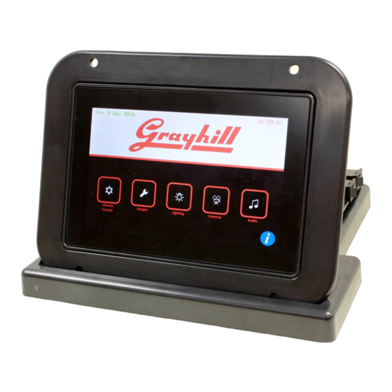
- Page 1 Series 3D70 Development Kit Quick Start Guide Bulletin 1286 rev.0817...
-
Page 2: Revision History
Revision History Revision Date Description 11/11/2016 Original Release 08/25/17 Minor corrections; Added Appendix A with development board schematic information 3D70 Dev Kit – Quick Start Guide Bulletin 1286 rev.0817... -
Page 3: Hardware Setup Instructions
Introduction These instructions describe how to connect the 3D70 Display to its development board and how to connect the power, Ethernet, CAN bus, and RS-232 serial bus. Equipment from Grayhill Included with 3D70Dev-100 Kit 3D70VT-100 Display 3D70 Mounting Frame ... - Page 4 2. Notice that the 3D70 Mounting Frame has two openings on the back and that one is larger than the other. Place this mounting frame on top of the 3D70 Display with the larger opening to the left (over the connector marked “A”).
- Page 5 Connect the two 18- pin DT cables to the back of the display. Note that the cables are different! Match up the keying tabs to insure that the correct cable is installed in the correct connector on the back of the 3D70 Display.
- Page 6 6. Connect the two 18- pin DT cables to the 3D70 breakout board. Be sure to connect cable “A” to the connector marked “A” on the breakout board and cable “B” to the “B” connector. Also be sure to match up the keying tabs with the keying tab silk- screened on the...
- Page 7 9. Attach a DB9 cable to the CAN 1 port on the Breakout Board. 10. Attach the other end of this cable to the matching connector on the USB to CAN adapter. 11. Plug the USB plug on the CAN adapter into a USB port on the development PC.
- Page 8 12. Connect DB9 serial cable to Breakout Board COM 1 port. Attach other end of this cable to a serial port on the development PC. 13. Connect Ethernet cable to the Ethernet port on the development board. The other end of the Ethernet cable should be connected to the same network that...
- Page 9 PC to CAN-bus Interface The Series 3D70 Display device has two CAN bus interfaces that can be used for various purposes. The GridConnect USB-to-CAN adapter and software is a PC to CAN-bus interface that can be used for monitoring and sending messages on the CAN bus. The GridConnect software can be installed on the development PC as shown below: 1.
-
Page 10: Power Requirement
Appendix A POWER REQUIREMENT Voltage: 12V Current: 1.5A J4, J6, J7, J9, J10 J2, J3 TE CONN TE CONN TYCO PJ-002AH RCJ-014 555153-1 747844-6 292303-1 J1, J8 MATING CONNECTORS HOUSING: J1=DEUTSCH DT16-18-SA-K004, J2= DEUTSCH DT16-18-SB-K004 TERMINAL: DEUTSCH 0462-201-16141 BOARD LAYOUT 3D70 Dev Kit –... - Page 11 MAIN CONNECTOR “A” (J1) MAIN CONNECTOR “B” (J8) POWER SWITCHES VBAT (SW1) and VSW (SW2) 3D70 Dev Kit – Quick Start Guide Bulletin 1286 rev.0817...
- Page 12 VIDEO INPUTS CAM1 (J2), CAM2 (J3), and CAM3 (J13) 3D70 Dev Kit – Quick Start Guide Bulletin 1286 rev.0817...
- Page 13 CAN CONNECTORS CAN1 (J6) and CAN2 (J7) 3D70 Dev Kit – Quick Start Guide Bulletin 1286 rev.0817...
- Page 14 RS232 CONNECTOR COM1 (J9) IO CONNECTORS (J4, J10) 3D70 Dev Kit – Quick Start Guide Bulletin 1286 rev.0817...
-
Page 15: Usb Connector (J5)
USB CONNECTOR (J5) ETHERNET CONNECTOR (J11) 3D70 Dev Kit – Quick Start Guide Bulletin 1286 rev.0817... - Page 16 DIP Switch SW3 Leave all switches open (OFF) for normal operation. Closing switches 5,6 (ON) connects CAN port 1 to CAN port 2. Closing switch 4 (ON) connects OUT4 to DIG_IN4 Closing switch 3 (ON) connects OUT3 to DIG_IN3 Closing switch 2 (ON) connects OUT2 to DIG_IN2 Closing switch 1 (ON) connects OUT1 to DIG_IN1 3D70 Dev Kit –...
- Page 17 LEDs D2,D3,D4, D5, and D6 LEDs are illuminated if their corresponding signal is high. 3D70 Dev Kit – Quick Start Guide Bulletin 1286 rev.0817...
Need help?
Do you have a question about the 3D70Dev-100 Kit and is the answer not in the manual?
Questions and answers