
Related Manuals for heatpumps 4pools ThermoTec LCSPI-95BP

Summary of Contents for heatpumps 4pools ThermoTec LCSPI-95BP
- Page 1 Swimming Pool Heat Pump - Operation and Installation Manual - Model:LCSPI-95BP,LCSPI-135BP,LCSPI-180BP, LCSPI-220BP, LCSPI-280BP...
-
Page 2: Table Of Contents
TABLE OF CONTENT INTRODUCTION…………...………………………………………………………………………………………………..2 This manual……………………………………………………………………………………………………………………... 2 ………………………………………………………………………………………………………..The Heat Pump ..SAFETY INSTRUCTIONS ……………………………………………………………………………………………………. 3 ……………………………………………………………………………………………………………………….……. 3 Warning ……………………………………………………………………………………………………………………………. 4 Caution… CONTENTS……………….…………………………………………………………………………………………….………... 4 OVERVIEW OF THE UNIT ……………………………………………………………………………………….…………. 5 EXPLODED VIEW ……… ……………………………………………………………………………………….………………6 INSTALLATION …………………………………………………………………………………………….…..….…….…….. 7 …………………………………………………………………………………………….…..………. 7 Installation guidelines ….……………………………………………………………………………….…………………………... -
Page 3: Introduction
INTRODUCTION This manual This manual includes the necessary information to safely install and maintain your Heat Pump. Please read this manual carefully before you operate the unit. The Heat Pump The swimming pool heat pump is one of the most economical ways of heating your swimming pool efficiently. -
Page 4: Safety Instructions
SAFETY INSTRUCTIONS To prevent injury to the user, other people or damage to property, the following instructions must be followed. Install the unit only when it complies with local regulations, by-laws and standards. Check the main voltage and frequency. This unit must be earthed and have a supply voltage of 220 – 240 V ~ / 50Hz. The following safety precautions should always be taken into account: Be sure to read the following WARNING before installing the unit. -
Page 5: Caution
Water Connections. All plumbing connections should be carried out as per the instructions in this manual. Failure to do so could result in water damage to property. Cleaning the Unit. To prevent injury always shut the power ‘OFF’ when cleaning or servicing the unit. Error Codes. -
Page 6: Overview Of The Unit
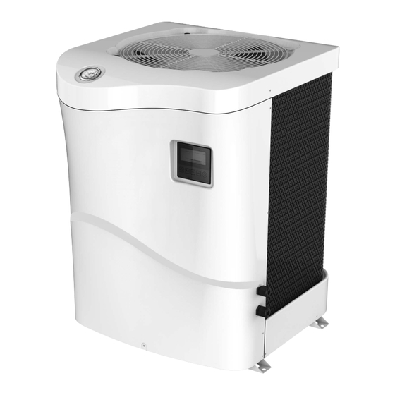
OVERVIEW OF THE UNIT... -
Page 7: Exploded View
EXPLODED VIEW... -
Page 8: Installation
INSTALLATION Installation guidelines The following information is for guidance only. Locating the Unit The unit should be located on a solid, flat, horizontal surface. Ensure 3 metres of free air flow to the discharge panel and 1 metre to the inlet panel. Ensure adequate access to the controller and for maintenance purposes. -
Page 9: Electrical Connection
Electrical connection The Electrical supply must correspond to that indicated on the appliance. All supply cables have to be sized according to the appliance power and installation requirements. Please refer to below table: The above are an indication only.Please refer to a qualified Electrician if in doubt. Use the cable glands and grommets provided inside the heat pump to secure and route the supply cables. -
Page 10: Operating The Unit
Features and functions Basic controller functions The basic controller functions are: Turning the heat pump ‘ON’/’OFF’. 24 hour time clock. Timer ‘ON’ and timer ‘OFF’. Parameter adjustment User interface NEVER LET THE DIGITAL CONTROLLER GET WET. THIS MAY CAUSE AN ELECTRIC SHOCK OR FIRE. NEVER PRESS THE BUTTONS OF THE DIGITAL CONTROLLER WITH A HARD, POINTED OBJECT. -
Page 11: Buttons
Buttons Unit ON/OFF button Press this button for 3 second to switch unit ON/OFF. Mode button Under main operation interface when unit ON,press this button for 3 seconds to switch heating or cooling modes. adjustment buttons ... -
Page 12: Parameter Checking And Adjustment
Press for 3 seconds entering into mandatory defrost mode. Factory reset Press for 3 seconds entering into factory reset. PARAMETER CHECKING AND ADJUSTMENT Unit running status query On main operation interface,press for 3 seconds to check temperatures,see the following table: Code Temperature Name... -
Page 13: System Protections/Error Codes
Defrost cycle 20MIN~90MIN 45MIN Defrost entry coil temp -15℃~-1℃ -3℃ Defrost duration time 5MIN~20MIN 10MIN Defrost exit coil temp 1℃~40℃ 20℃ Ambient/coil temp difference for defrost entry 0℃~15℃ 5℃ Ambient temp for defrost entry 0℃~20℃ 17℃ EEV action cycle 20S~90S Heating EEV action factor -5℃~10℃... -
Page 14: Maintenance
Er 21 Ambient temp sensor failure Er 23 Outlet cooling water over-cold protection Er 27 Outlet water temp sensor failure Er 29 Return gas temp sensor failure Er 32 Outlet hot water over-heat protection Er 35 Compressor current protection MAINTENANCE To protect the paintwork, avoid leaning or putting objects on the shell. -
Page 15: Troubleshooting
TROUBLESHOOTING This section provides useful information for diagnosing and correcting certain prolems which may occur. Before starting the troubleshooting procedure, carry out a thorough visual inspection of the unit and look for obvious defects such as loose connections or defective wiring. Before contacting your local dealer, read this chapter carefully.It could save you time and money. -
Page 16: Disposal Requirements
DISPOSAL REQUIREMENTS Dismantling of the unit, treatment of the refrigerant, of oil and of other parts must be carried out in accordance with relevant local and national legislation. Your product is marked with this symbol. This means that electrical and electronic products should not be mixed with unsorted household waste. -
Page 17: Wiring Diagram
WIRING DIAGRAM Please refer to the wiring diagram on the electric box. LCSPI-135/180/220BP... -
Page 18: Inverter Swimming Pool Heat Pump Technical Specification
Inverter Swimming Pool Heat Pump Technical Specification Model LCSPI-95BP LCSPI-135BP LCSPI-180BP LCSPI-220BP LCSPI-280BP Air 27℃,Water Capacity(kW) 10.23~2.55 14.11~3.52 19.12~4.78 22.79~5.69 28.68~7.16 inlet/outlet:26℃ 16.11~6.14 16.23~6.19 16.18~6.15 16.09~6.12 16.07~6.11 /28℃, Humidity 80% Air 15℃,Water Capacity(kW) 8.06~2.01 11.02~2.75 14.11~3.52 17.18~4.29 21.53~5.38 inlet/outlet:26℃ 8.16~4.72 8.22~4.75 8.19~4.73 8.11~4.63...
Need help?
Do you have a question about the ThermoTec LCSPI-95BP and is the answer not in the manual?
Questions and answers