Advertisement
APPLICATION
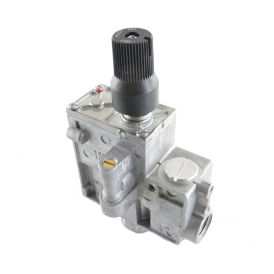
The AF-1000 Manual Gas Control Valve is designed for use in gas in hearth products, wall mount furnaces, and space heating
appliances. For use with Propane or natural gas.
AF-1XXX MODEL IDENTIFICATION
A
F
1
f i r e - p a r t s . c o m
American Flame
1000 Series
FEATURES
Multi positional (All Plans) / Versatile Mounting.
•
Power unit powered by 30mv thermocouple.
•
CSA rated capacity 80,000 BTU/hr at 1" wc pressure drop (All inlet/outlet configurations).
•
AF-1000 series available with 0ºF to 225ºF (-18
•
Multiple outlet connections single inlet connection (All 3/8" NPT).
•
Fine mesh screens on inlet.
•
Multiple mounting holes (All 10-24 SAE threads)
•
Low profile / Compact size.
•
Easy pilot adjustment screw (Located on the front of the valve) (Vented Only).
•
No conversation from natural to propane gas required.
•
White lettering on OFF/ON/PILOT knob.
•
Vented / Vent free models available.
•
1" and 2" plastic extension knobs available.
•
A M E R I C A N F L A M E
X
X
X
0 = Manual without Solenoid.
1 = With ON/OFF Solenoid (Remote)
2 = With ON/OFF/Variable DC Motor Drive (Remote)
3 = With High/Low Step Motor (Model AF-1000MOT)
4 = Manual for 3-Plunger Safety Seal
Type of Valve
0 = Vented Control Valve
1 = Ventfree Control Valve
0
C to 107ºC) temperature range.
Manual Gas Control Valve
0 = With Safety Seal
1 = With Safety Seal (3-Plunger)
5 = With-out Safety Seal
A F
AF-1000 Series
REV. 1/9/2010
Page 1 of 9
Advertisement
Table of Contents

Related Manuals for american flame AF-1000 Series


Summary of Contents for american flame AF-1000 Series
- Page 1 Power unit powered by 30mv thermocouple. • CSA rated capacity 80,000 BTU/hr at 1” wc pressure drop (All inlet/outlet configurations). • AF-1000 series available with 0ºF to 225ºF (-18 C to 107ºC) temperature range. • Multiple outlet connections single inlet connection (All 3/8” NPT).
-
Page 2: Specifications
2.0” Inlet @ 1.0” outlet = 1.0” pressure drop f i r e - p a r t s . c o m Btu/hr X 1K This information is American Flame lab generated data and is to be used as reference only. SPECIFICATIONS Main Gas Connections: Valve: 3/8 in. - Page 3 DIMENSIONS f i r e - p a r t s . c o m REV. 1/9/2010 Page 3 of 9...
-
Page 4: Installation
INSTALLATION When Installing this Product…. Read these instructions carefully. Failure to follow these instructions completely could damage the product or cause a • hazardous condition. Check the ratings given in the instructions and on the product to make sure the AF-1000 Gas Control is suitable for your •... -
Page 5: Install Control
Install Control 1. Mount control 0 to 90 degrees in any direction, from the upright position of the gas control knob, including vertically. 2. Mount the control so gas flow is in the direction of the arrow on the side Figure #2 or back of the control. -
Page 6: Shut Off Procedure
Pilot Gas and Lighting Procedure Turn the gas control knob counterclockwise to the PILOT position, push the gas control knob IN and HOLD in • position. This will open the pilot valve and allows gas to flow to the pilot burner. Light the pilot burner while holding the gas control knob in until a strong pilot flame is present. - Page 7 DC powered feature of the AF1000 The AF-1000 has a non-leak safety feature that allows the installation of an ON/OFF solenoid. Note: Figure #9 With the use of this DC powered latching ON/OFF solenoid allows the use of a DC powered switch or remote control (Model CON 1001) NOTE: The AF-1025 and AF-1125 (ONLY) do not have a non-leak safety feature.
-
Page 8: Maintenance
Equipment Danger Hazard. Improper adjustment of gas input and burner can cause carboning and/or unnecessary shutdown of the system. 1. Do not exceed the input rating stamped on the appliance nameplate, or manufacture recommended burner orifice pressure for size orifice(s) used. Be sure primary air supply to the main burner is properly adjusted for complete combustion. Follow the instructions of the appliance manufacturer. -
Page 9: Troubleshooting
Limited Warranty American Flame, Inc. warrants the AF-1000 Valve series for 12 months from the date of purchase or installation to the original purchaser to be free from defects in materials and workmanship. Damage to the AF-1000 Valve caused by accident, misuse, abuse, or installation error, whether preformed by a contractor, service company, or owner, is not covered by this warranty.
Need help?
Do you have a question about the AF-1000 Series and is the answer not in the manual?
Questions and answers