Table of Contents
Advertisement
O R I G I N A L I N S T R U C T I O N S
Installation, Setup
and Operation
INSTRUCTIONS
for
SUNNEN
Models:
READ THE FOLLOWING INSTRUCTIONS THOROUGHLY AND CAREFULLY BEFORE UNPACKING,
INSPECTING, OR INSTALLING THE SUNNEN
"SUNNEN
®
AND THE SUNNEN LOGO ARE REGISTERED TRADEMARKS OF SUNNEN PRODUCTS COMPANY."
SUNNEN
®
PRODUCTS COMPANY • 7910 MANCHESTER ROAD • ST. LOUIS, MO 63143, U.S.A. • PHONE: 314-781-2100
®
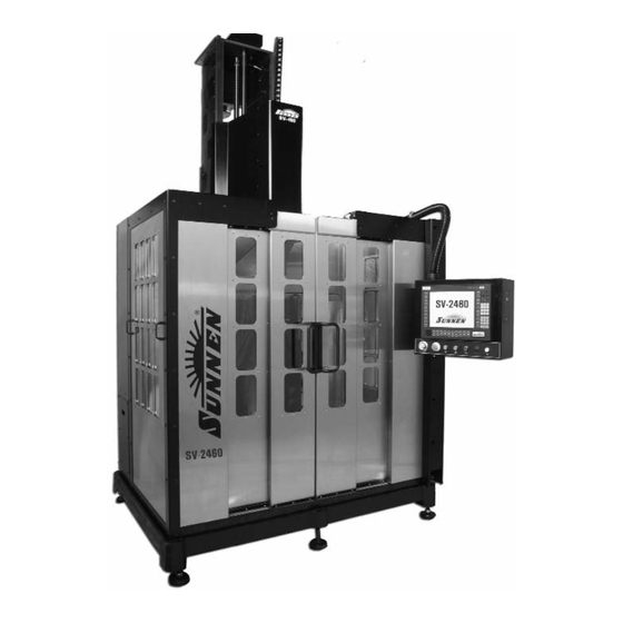
VERTICAL HONING MACHINE
SV-2460
®
SV-2460 VERTICAL HONING MACHINE.
I-SV-461
Advertisement
Table of Contents
Troubleshooting

Related Manuals for Sunnen SV-2460

Summary of Contents for Sunnen SV-2460
- Page 1 INSPECTING, OR INSTALLING THE SUNNEN ® SV-2460 VERTICAL HONING MACHINE. “SUNNEN ® AND THE SUNNEN LOGO ARE REGISTERED TRADEMARKS OF SUNNEN PRODUCTS COMPANY.” SUNNEN ® PRODUCTS COMPANY • 7910 MANCHESTER ROAD • ST. LOUIS, MO 63143, U.S.A. • PHONE: 314-781-2100...
-
Page 2: Esd Prevention Review
Troubleshooting information can also be found within the Instructions. If you cannot find what you need, call for technical support. Where applicable, programming information for your Sunnen equipment is also included. Most answers can be found in the literature packaged with your equipment. -
Page 3: Sunnen Software License Agreement
SUNNEN SOFTWARE LICENSE AGREEMENT ® This document is a Legal Agreement between you, as user and licensee (Licensee), and Sunnen ® Products Company (SPC) with respect to preprogrammed software (Software) provided by SPC for use on SPC Equipment. By using the Software, you, as Licensee, agree to become bound by the terms of this Agreement. -
Page 4: Important Note
35º to 46º C (95º to 115º F). IT IS NOT recommended that the SV Machine be operated at temperatures above 46º C (115º F). Sunnen Products Company warrants the SV Machine for operating environments up to 35ºC (95º F). For operating environments of 35º... -
Page 5: Table Of Contents
Sunnen® Software License Agreement ........ -
Page 6: General Information & Specifications
Diameter range, length range, and workpiece weight are contingent on workpiece and application. The SV-2460 does NOT come with Coolant or Pneumatic Systems. These Systems are optional and MUST be order separately. Work Area includes Machine Floor Space plus clearance for operator to move around machine. -
Page 7: Section 1 Installation
INSTALLATION GENERAL 1. Move Machine to staging/unpacking area. Consult this section when unpacking, inspecting, 2. Remove plastic wrap. and installing Sunnen ® Vertical Honing Machine 3. Remove top and sides from packing crate. (see Figure 1-1). Hereafter referred to as the machine. - Page 8 9. Level and stabilize Machine by placing a millwright's level on ground Table Base (see Figure 1-3). Machine JAM NUT needs to leveled both from front to back and left to LEVELING right. BOLT NOTE: Machine does not need to be bolted to floor but should be set on 1/2"...
- Page 9 HANGER STRAP CONDUIT FORKS GUIDE LINES FIGURE 1-6, Wiring Conduit BLOCK FIGURE 1-9, Column COLUMN SCREW GUARDING SHIPPING BASE MOTOR FIGURE 1-7, Left & Right Rear Guarding FIGURE 1-10, Shipping Base 13. Remove Hardware securing Wiring Conduit to rear of Machine and tie Wiring Conduit off to side of Machine (see Figure 1-6).
-
Page 10: Column Electrical Connection
18. Raise Forks and slide into Lifting Sleeves (see Figure 1-8). 19. If required: Secure top of Column to top of Fork COLUMN Lift using straps (see Figure 1-9). 20. If required: Place a Block between the Fork Lift and bottom of the Column to prevent the column from swinging when it is lifted (refer to Figure 1-9). - Page 11 MACHINE ELECTRICAL CONNECTION All wiring is to be performed by a competent, Licensed Electrician in accordance with all local, state, and federal codes and regulations; along with any special information provided on machine nameplate or electrical specification plate (see Figure 1-15).
-
Page 12: Electrical Connection
A pre-drilled hole has been provided in NOTE: MASTER Electrical Enclosure for Electrical Supply Cord (not ON/OFF supplied). Connect Cord as follows (refer to Figure SWITCH 1-15). WARNING NAMEPLATE Residual Voltage exists for 2-3 minutes after Master ON/OFF Switch is turned OFF. Before working inside Enclosure, wait for all fans to stop running to allow drives to discharge. -
Page 13: Coolant System Connection
Check with your local Sunnen Field Service Engineer or Sunnen Products Company FIGURE 1-18 Magnetic Separator Technical Services. Grease Reservoir is filled at the factory with Sunnen 90123 (Kluberplex #BEM34-132 or its equivalent) OPERATIONAL CHECK (see Figure 1-16). - Page 14 NOTES...
-
Page 15: Section 2 Preparing For Operation
DRIVE TUBE - 7A - SUMP PUMP - 8 - (OPT) COOLANT SYSTEM - 1C - - 1A - STAINLESS MACHINE STEEL DOORS BASE - 1B - - 5 - (OPT) LEVELING WORKHOLDING BOLTS FIXTURE FIGURE 2-1, SV-2460 Honing Machine... - Page 16 YCOM POWER DISK INPUT FAULT PF11 CTRL SHIFT PF12 BACK- SPACE SPACE PF13 PF14 & YCOM POWER DISK INPUT FAULT PF15 PF16 PF17 PgUp PgUp PF18 < CTRL SHIFT HOME PF11 PF19 PgDn > PF10 ENTER PF20 PF12 BACK- SPACE SPACE PF13 PF14...
-
Page 17: Operator Controls
5. Workholding Fixture (opt) CAUTION 6. The Adjustable Coolant Lines allows manual Use of tooling other than Sunnen tooling will render regulation of honing fluid flow through the all of features of computerized honing system 7a. The Sump Pump pumps coolant from the useless, due to fact that machine and all its machine base reservoir. -
Page 18: Honing Tool Setup
HONING TOOL SETUP When using CK/CV or GHSS/GHTS Series Hone Heads proceed to, Installing Hone Head. DRIVE DRIVE TUBE When using P20/P28 Mandrel and CV1010 Mandrel TUBE Adapter, proceed with the following steps: SETSCREW P20/P28 Mandrel & Mandrel Adapter Following is a setup guide using mandrel adapter. MANDREL ADAPTER 1. - Page 19 16. Place other alignment guide in left-hand set of holes above numeral "2" in hone body, so guide and stone are also in line. GHSS-Series Hone Heads Sunnen GHSS-Series Single Stage Honing Tools GRADUATED consists of four sets of six (6) to eight (8) spring SLIDE loaded stoneholders, which utilize Sunnen abrasives.
- Page 20 4. Fill the empty slots in hone head with new stone holders, and reattach springs. 5. Proceed to next two stone holders and repeat steps. Truing Stones Sunnen diamond abrasive honing stones have been GHTS HONE pre-ground to a radius and can be used directly from HEAD the box.
- Page 21 1. Verify hone head is fully retracted. Both sets of Sunnen GHTS-Series Two Stage Honing Tool uses expander plates should be flush against the hone Sunnen GH Stone Sets and PHT Brush Sets. body once inserted into their correct numbered slot. Install GH-Series Hone Head by sliding Hone Head 2.
- Page 22 NOTES...
-
Page 23: General
• Keep Machine and area around machine cleaned or replacement accessories. Using parts or accessories of excessive lubricant and lubricant spills. other than those approved by Sunnen could result in • Keep tools and other foreign objects clear of damage to machine and loss of warranty. -
Page 24: Setup - Initial
(see Figure 3-1). Using up and down ARROW keys, load graph to determine RUL, ideal condition is to you can move this marker to a place in bore that you have trend of graph be horizontal. If trend is upward, would like to dwell. -
Page 25: Safe Shutdown (Turning Machine Off)
• Key in desired value using key pad - Press OK to 15. Set tool SNUG diameter by moving tool around accept. in bore, while using handwheel, expand tool (CW) or retract tool (CCW), until tool feels snug in bore. BORE LENGTH: 3.50000 •... - Page 26 NOTES...
-
Page 27: Section 4 Routine Maintenance
(Gage on front of Coolant System), and add coolant as necessary. FILTER COVER CAUTION DO NOT overfill system. • If using Sunnen Coolant Concentrate, check concentration and add water or concentrate as necessary. FILTER Every 1000 Hours: • Remove the sheet metal covers that are attached to the carriage. -
Page 28: Filter Element Replacement
The operator station will indicate if the limit is close to being reached. • Grease the x-axis carriage and stroker carriage runner blocks using Sunnen 90123 (Kluberplex #BEM34-132 or its equivalent). The ends of the runner block assemblies have Zerk fittings. Each runner block will need approximately 2.2 ml. -
Page 29: Sump Drain Cleaning
Replacement Elements and parts are NOTE: there is a noticeable drop in coolant pressure. available through the Sunnen or your local supplier. 1. Turn OFF power at Master ON/OFF Switch. 8. Snap Filter Cover into place over Filter Element. 2. Remove Drain Cover in right side of machine base, 9. -
Page 30: Pneumatic Line Check
7. Loosen tension on Idler Pulley, by loosening SCREWS tension Screw in Tension Block Assembly (see SPINDLE Figure 4-8). STRAP 8. Remove old belt and replace with new belt. BELT 9. Use tension Screw to tension belt. (New Belt: IDLER Tension belt so that deflection at midway between PULLEY pulleys is approximately 9,5mm (.38in) when a 40N... - Page 31 BOWL FIGURE 4-10, PH Tooling (Optional) DRAIN NOTE: When using Sunnen PH-Series Precision Multi-Stone Honing Tools with integral air gage available for in-process measurement for optimum control of the bore diameter; inspect Pneumatic Lines (airlines) and Fittings running to tool monthly for leaks or damaged parts.
- Page 32 NOTES...
-
Page 33: Section 5 Troubleshooting
*NOTE: Many honing problems, such as poor tool life and rough finish, are caused by the following: the wrong coolant, insufficient coolant, dirty coolant, or contaminated coolant. Use ONLY clean, full-strength Sunnen Industrial Honing Oils or Water-Based Coolants. DO NOT dilute or “cut” the oil or coolant in your Machine with... - Page 34 *NOTE: Many honing problems, such as poor tool life and rough finish, are caused by the following: the wrong coolant, insufficient coolant, dirty coolant, or contaminated coolant. Use ONLY clean, full-strength Sunnen Industrial Honing Oils or Water-Based Coolants. DO NOT dilute or “cut” the oil or coolant in your Machine with...
-
Page 35: Machine Troubleshooting
ALWAYS have power OFF when guards are open. replaced. If problem cannot be diagnosed by Power Off inspection, then consult a Sunnen Service 2. If grease is not seen coming out of one or more Technician. injector, then remove the injector(s) from the manifold. - Page 36 NOTES...
-
Page 37: A - Coolant System (Opt)
A - COOLANT SYSTEM (OPT) FLOW DIAGRAM SUMP PUMP OPTIONAL COOLANT SYSTEM FLOW CONTROL ON/OFF VALVE WORKPIECE SUMP PUMP PUMP MACHINE RESERVOIR PAPER FILTER FILTERED OPTIONAL FLUID COOLANT SYSTEM with PAPER FILTER MAGNETIC SEPARATOR OPTIONAL COOLANT SYSTEM with MAGNETIC SEPARATOR FIGURE A-1, Coolant System Flow Diagram... - Page 38 NOTES...
-
Page 39: B - Grease Pump
B - GREASE PUMP FLOW DIAGRAM LUBRICATOR FILLER PORT HOUSING TO BALLSCREW (STROKER) TO BALLSPLINE (STROKER) FIGURE B-1, Grease Lubrication System Flow Diagram... - Page 40 NOTES...
-
Page 41: C - Declaration Of Conformity
C - DECLARATION OF CONFORMITY (1 OF 2) - Page 42 C - DECLARATION OF CONFORMITY (2 OF 2)
- Page 43 WARNING An Arc Flash Hazard Exists. Follow safe work practices and wear appropriate Personal Protective Equipment. Follow proper lockout/tagout procedures. Failure to comply can result in death or injury. Like any machinery, this equipment may be dangerous if used improperly. Be sure to read and follow instructions for operation of equipment.
- Page 44 3.281 FEET (ft) – S WITZERLAND UNNEN “SUNNEN ® AND THE SUNNEN LOGO ARE REGISTERED TRADEMARKS OF SUNNEN PRODUCTS COMPANY.” Phone: ++ 41 71 649 33 33 Fax: ++ 41 71 649 34 34 www.sunnen.ch e-mail: info@sunnen.ch S.R.L. TALY UNNEN...
Need help?
Do you have a question about the SV-2460 and is the answer not in the manual?
Questions and answers