
Related Manuals for Leader Electronics Corp. LAG-120A


Summary of Contents for Leader Electronics Corp. LAG-120A
- Page 1 All manuals and user guides at all-guides.com L A G - 1 2 0 A MO DE L AUDIO GENERATOR INSTRUCTION MANUAL LEADER ELECTRONICS CORP.
- Page 2 All manuals and user guides at all-guides.com...
- Page 3 All manuals and user guides at all-guides.com LAG-120A AUDIO GENERATOR GENERAL DES CRIPTION Uses The LAG-120A is a wideband audio generator with sine and square output waveforms. Sine wave signals are available with a distor of less than 0.4%. Square waves with fast rise time can be used for circuit performance checks.
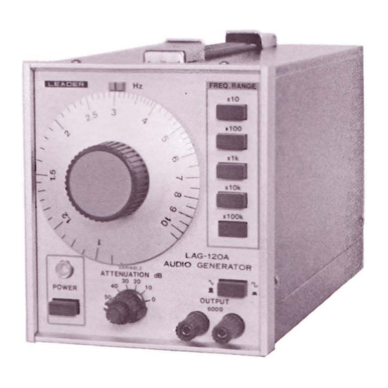
- Page 4 All manuals and user guides at all-guides.com FREQ. R ANGE switches: For selection of the output frequency ranges: 100Hz 1000Hz (1kHz) x100 10kHz 100kHz x10k veforms. Sine 1000kHz (lMHz) x100k rise time c a n Frequency dial: Marked in Hz: to 10;...
- Page 5 All manuals and user guides at all-guides.com � sh01 maximum req - red. ey e. he in Sin e Fig. Rear panel functions. Cs e In m OPERATION PO ,,£ Preliminary Notes The generator output impedance is 600n, and may be directly connected to loads of 600n higher impedances.
- Page 6 All manuals and user guides at all-guides.com �:\G-120A LBO-S13A LMV-181A ©D@ 0°0 � AMPLIFIER Fig. Equipment and connections for measurements. The specified load resistance. R. is connected across the output of the amplifier, or test circuit. It should be non-inductive and have a wattage rating at least twice the expected maximum power output.
- Page 7 All manuals and user guides at all-guides.com Frequency Response The frequency response of amplifier is determined applying a constant voltage to the amplifier input. This voltage is chosen so that the amplifier is operated below the overload point. Set the reference frequency 1kHz or 400Hz, and set ATTENUATION and VARI- ABLE for suitable amplifier output.
- Page 8 All manuals and user guides at all-guides.com avesha pe Amplifier Response Condition RECTANGULAR SATISFACTORY FLAT LOW PRIMARY INDUCTANCE INOUTPUT TRANSFORMER: INCORRECT VALUES OF THE DEFICIE. COUPLING ELEMENTS T LOW FREQUENCIES ROUNDING HIGH LEAKAGE INDUCTANCE � OUTPUT TRANSFORMER OR HIGH DISTRIBUTED CAPACITANCE IN CIRCUIT DEFICIE T HIGH FREQUENCIES GING...
- Page 9 All manuals and user guides at all-guides.com signal of exactly 1000Hz is applied, the oscillator will automatically lock in at 1000Hz. Thus, high accuracy can be achie v ed with the use of a precision frequency standard. In another application, a distorted waveform can be "purified", or filtered, by passing it through the oscillator.
- Page 10 All manuals and user guides at all-guides.com...
- Page 11 All manuals and user guides at all-guides.com Square wave adjustmen t. Fig. 3 - 3 Frequency Adjustment: Connect a frequency counter the OUTPUT terminals. 1. Set the FREQ. RANGE switch x1k, and the dial at "I" Set the waveform switch at sine. 2.
- Page 12 All manuals and user guides at all-guides.com § \.;.l :?:l V> ;:;:; .., I' ", UHII I I'� 111111" 11,,,"11111 11'1'. 101, I"U" 'I� �'",� 11/1 " ·0 �. ItOl 'WIll i , II I tHII " ! IICIII '1q"f I,f! Iflill...
- Page 13 All manuals and user guides at all-guides.com LEADER ELECTRONICS CORP. 2-6-33 TSUNASHIMA-HIGASHI. KOHOKU-KU, YOKOHAMA, JAPAN. PHONE: (045) 541 -2121 TELEX: J47780 JPLEADER LEADER INSTRUMENTS CORP. 3800SER AVENUE, HAUPPAUGE, N.Y. 11788 U.S.A. PHONE: (516) 231 -6900 TELEX: 510-227-9669 LEADER HAUP Printed in Japan. 85061.
Need help?
Do you have a question about the LAG-120A and is the answer not in the manual?
Questions and answers