Table of Contents
Advertisement
Quick Links
Advertisement
Table of Contents

Subscribe to Our Youtube Channel
Related Manuals for SCI MM-380A


Summary of Contents for SCI MM-380A
- Page 1 WELD TESTER MM-380A OPERATION MANUAL Thank you for your purchase of the Miyachi Weld Tester MM-380A. Please read this manual carefully to ensure correct use. Keep the manual handy after reading for future reference. K05M0811E-02 www.spotweldingconsultants.com...
-
Page 2: Table Of Contents
5. Operation Flow ..........................5-1 6. Preparations and Connections....................6-1 (1) Connecting the MM-380A and Power Supply ....................6-1 (2) Preparations for Measurement – Connection between the MM-380A and Measurement Devices..6-2 a. Connecting a toroidal coil ........................6-2 b. Connecting the Force Sensor.........................6-4 c. When using an external ±10V voltage input ...................6-5 7. - Page 3 (2) Configuration ................................12-1 (3) Protocol .................................12-2 a. Unidirectional communication mode (unidirectional in the COMMUNICATION screen).......12-2 13. Error List ..........................13-1 14. Specification ..........................14-1 (1) Measurement Specification..........................14-1 (2) Specification of the MM-380A .........................14-5 15. Calibration..........................15-1 16. Appearance ..........................16-1 EC Declaration of Conformity...
-
Page 4: Special Notes
MM-380A 1. Special Notes (1) Safety Precautions Before using the weld checker, please read through the Safety Precautions carefully to ensure proper use. The precautions listed here are designed to ensure safe use and proactively prevent risks and damage to the user and other people. - Page 5 MM-380A DANGER NEVER ATTEMPT to disassemble, repair or modify the instrument. Do not touch any parts inside the instrument. Failure to observe this may result in an electric shock or fire. For battery replacement, inspection or repair, please contact your dealer or Miyachi Corporation.
- Page 6 MM-380A CAUTION DO NOT splash water. Electrical parts may cause an electric shock or short circuit if they become wet. Keep the area clear of flammable objects. Surface flash and expulsion generated during welding may ignite flammable objects, resulting in a fire. If work involves use of flammable items, place a non-flammable cover over such items.
-
Page 7: Handling Precautions
MM-380A (2) Handling Precautions Avoid the following locations when installing the instrument: Humid location (humidity of 90% or more) Extremely hot (45°C or more) or cold (0°C or less) locations Near a radio frequency noise source Location where chemical substances, etc. are handled... -
Page 8: Features
MM-380A 2. Features Miyachi Corporation Weld Tester MM-380A is a hand-held measuring instrument designed for resistance welding machines. The instrument can measure the current, voltage, current flow time, force , and external input voltage (max. ± 10 V) and display their waveforms. -
Page 9: Packing List
MM-380A 3. Packing List Check the contents of the package. In the case of damaged or missing items, please contact Miyachi Corporation. (1) Accessories Item Item code Strap PC021923 Operation manual EV000886 Stereo Plug PA022402 3. Packing List... -
Page 10: Options
MM-380A (2) Options Item Model Item code MM-380A AC adapter BLM-110W PA021243 ACS-100J (Japan) PA021247 ACS-100U (US) PA021244 AC cable for the MM-380A AC adapter ACS-100G (Europe) PA021245 ACS-100E (UK) PA021246 MB-800K (approx. 250mm in dia.) Toroidal coil EI000006 MB-400K (approx. 120mm in dia.) -
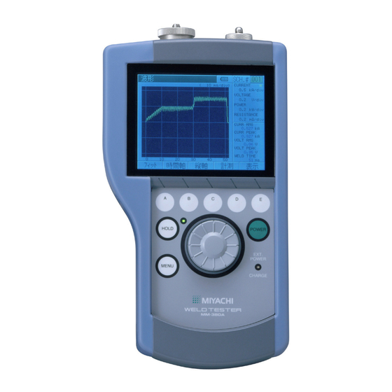
Page 11: Name And Function Of Each Part
The nature of the operation performed by pressing each button varies from one operation screen to another. Turns ON the power for the MM-380A. ⑥ POWER button: 4. Name and Function of Each Part... -
Page 12: Top
Used to select menus and parameters and confirm the selection. Refer to “(2) Using the Encoder” in Chapter 7 for basic use of the encoder. Lit when the MM-380A is connected to ⑧ EXT POWER/CHARGE lamp: an external power supply and blinked when charged. -
Page 13: Right Side
② AC adapter jack: Connect the dedicated AC adapter here when charging the battery built into the MM-380A or using an external power supply. CAUTION Connect only the dedicated AC adapter to the AC adapter jack. Failure to do so may result in malfunction, fire, or electric shock. -
Page 14: Rear
MM-380A ② RS-232C connector: Connector to connect the instrument and PC with an optional RS-232C communication cable. Used to transfer measured values and waveform data to the PC. (5) Rear ① ① Battery cover: A cover to protect the battery. The rechargeable lithium battery is housed under a cover, in a holder. -
Page 15: Operation Flow
MM-380A 5. Operation Flow The operation flow is shown below. Install the MM-380A (Refer to (1) in Chapter 6) Device connection Connect measurement devices to the MM-380A Connect with other devices Voltage Force measurement Sequencer Current measurement Toroidal coil Voltage... -
Page 16: Preparations And Connections
(1) Connecting the MM-380A and Power Supply To charge the built-in battery (lithium battery) or use an external power supply, connect the power supply to the AC adapter jack on the right side of the MM-380A with the dedicated AC adapter. -
Page 17: Preparations For Measurement - Connection Between The Mm-380A And Measurement Devices
MM-380A (2) Preparations for Measurement – Connection between the MM-380A and Measurement Devices a. Connecting a toroidal coil To measure current, plug a toroidal coil into the toroidal coil connector on the top of the of the MM-380A. Toroidal coil... - Page 18 MM-380A 2) Fit the toroidal coil onto the welding machine’s arm or secondary conductor. When fitting the coil, be careful with the following: • Keep the toroidal coil’s hooking bracket as far away from the welding machine’s arm (secondary conductor) as possible.
-
Page 19: Connecting The Force Sensor
• The MM-380A is calibrated one to one with the current/force sensor. Do not use any other sensors. If you purchase a current/force sensor later, the sensor and MM-380A must be adjusted as a set. In this case, please contact Miyachi Corporation. When you purchased the MM-380A and current/force sensor as a set, they have already been adjusted and can be used as is. -
Page 20: When Using An External ±10V Voltage Input
Apply force Electrode c. When using an external ±10V voltage input The MM-380A’s force/displacement-equipped specification allows for force measurement using a commercial force sensor and force sensor amplifier connected to the external ±10 V voltage input. (Have ready a force sensor and force sensor amplifier—purchased separately.) Follow the steps described below to connect the external ±10V voltage equipment. - Page 21 MM-380A 2) Plug the multiconnector into the multiconnector on the top panel of the MM-380A. Multiconnector Zoom 3) Connect the force sensor and the force sensor amplifier. CAUTION • Before measuring the force, be sure to set the force sensor's offset to "0."...
-
Page 22: Basic Operation
MM-380A 7. Basic Operation (1) Startup 1) To use an external power supply, connect the power supply to the AC adapter jack with the dedicated AC adapter. (Refer to Chapter 6(1).) 2) Press the POWER button. POWER button An operation screen appears on the display after a while. -
Page 23: Using The Encoder
MM-380A (2) Using the Encoder This section describes how to use the MM-380A’s encoder. You can perform the operations described in the table below by turning the encoder clockwise or counterclockwise. Down Selecting menus Moving cursor Right or Down Left or Up... -
Page 24: Moving The Cursor And Changing Parameters
MM-380A b. Moving the Cursor and Changing Parameters 1) Turning the encoder clockwise or counterclockwise, move to the input field of the desired parameter. You can move the cursor to the right or down by turning the encoder clockwise and to the left or up by turning it counterclockwise. -
Page 25: Scrolling A Screen
MM-380A c. Scrolling a Screen If the scroll (SCRL) key appears among the function keys at the bottom of the operation screen, you can scroll the screen using the encoder. 1) Press the operation button (one of A to E) below the SCRL key. -
Page 26: Shutdown
MM-380A (3) Shutdown 1) Press the POWER button. POWER button 7. Basic Operation... -
Page 27: Operation Screens
(1) Operation Screen Organization Press the MENU button to display the menu list, and select a menu using the encoder. At this time, the operation screen for the selected menu appears. The MM-380A’s operation screens are organized as shown below. - Page 28 MM-380A • Making Measurement while Displaying Data on Screen You can measure current, force and others in the MEASUREMENT, WAVEFORM and ALL CYCLE screens. The MEASUREMENT screen accepts next measurement even while the screen is being updated following a measurement.
-
Page 29: Description Of The Operation Screens
Pressing operation button D saves the (SAVE) measured values, all cycle, and waveforms to flash memory in the MM-380A. The MM-380A operates in the same manner as when saving the HISTORY screen. For more information, refer to the description of the HISTORY screen. -
Page 30: View Screen
MM-380A b. VIEW screen Item Description Measurement Select five measurement items from the following: (MEAS) 1 to 5 CURRENT (RMS) Shows the arithmetic mean RMS current over the measurement interval in arithmetic mean mode. CURRENT (PEAK) Shows the peak current during current flow. -
Page 31: Waveform Screen
MM-380A Item Description Measurement REAL TIME FORCE The MM-380A constantly measures the force while the (MEAS) 1 to 5 hold is canceled. The MM-380A stops measurement (Continued when put in hold mode. Measurement is made at from previous intervals of twice a second. Here, if you wish to select... -
Page 32: Waveform Screen (Time Axis)
MM-380A c. WAVEFORM screen Item Description SCH.# Shows the measurement condition number used (1 to 127). On the other hand, you can change conditions by selecting this field with the encoder and turning the encoder clockwise or counterclockwise. The details of the conditions can be set using the SETUP (1) to (3) screens. -
Page 33: D. Waveform Screen (Time Axis)
MM-380A d. WAVEFORM Screen (Time Axis) Item Description SCH.# Shows the measurement condition number used (1 to 127). On the other hand, you can change conditions by selecting this field with the encoder and turning the encoder clockwise or counterclockwise. The details of the conditions can be set using the SETUP (1) to (3) screens. -
Page 34: Waveform Screen (Vertical Axis)
MM-380A e. WAVEFORM Screen (Vertical Axis) Item Description SCH.# Shows the measurement condition number used (1 to 127). On the other hand, you can change conditions by selecting this field with the encoder and turning the encoder clockwise or counterclockwise. The details of the conditions can be set using the SETUP (1) to (3) screens. -
Page 35: Waveform Screen (Measurement Mode)
MM-380A f. WAVEFORM Screen (Measurement Mode) Cursor Item Description SCH.# Shows the measurement condition number used (1 to 127). On the other hand, you can change conditions by selecting this field with the encoder and turning the encoder clockwise or counterclockwise. The details of the conditions can be set using the SETUP (1) to (3) screens. -
Page 36: All Cycle Screen
MM-380A g. ALL CYCLE screen Item Description SCH.# Shows the measurement condition number used (1 to 127). On the other hand, you can change conditions by selecting this field with the encoder and turning the encoder clockwise or counterclockwise. The details of the conditions can be set using the SETUP (1) to (3) screens. -
Page 37: All Cycle (Force) Screen
MM-380A h. ALL CYCLE (Force) Screen Item Description SCH.# Shows the measurement condition number used (1 to 127). On the other hand, you can change conditions by selecting this field with the encoder and turning the encoder clockwise or counterclockwise. The details of the conditions can be set using the SETUP (1) to (3) screens. -
Page 38: Waveform (Force) Screen
MM-380A i. WAVEFORM (FORCE) screen Item Description SCH.# Shows the measurement condition number used (1 to 127). On the other hand, you can change conditions by selecting this field with the encoder and turning the encoder clockwise or counterclockwise. The details of the conditions can be set using the SETUP (1) to (3) screens. - Page 39 MM-380A Item Description Force time (Continued from previous page) Function keys Pressing operation button A redisplays the waveforms by automatically resizing them to fit into the screen by the FIT feature. Position Pressing operation button B makes it possible (MOVE) to move the waveforms.
-
Page 40: Setup (1) Screen
MM-380A j. SETUP (1) Screen Item Description SCH.# Select a measurement condition number (1 to 127) to set in the SETUP (1) to (3) screens. You can change condition numbers by selecting this field with the encoder and turning the encoder clockwise or counterclockwise. - Page 41 MM-380A Item Description Parameter TRIGGER MODE: SINGLE TRACE setting /MODE Current single-trace mode The instrument measures the maximum (Continue measurement range of current upon input d from of a current signal, after which it enters previous hold mode. page) The instrument shows “-” in the measured...
- Page 42 MM-380A Item Description Parameter TRIGGER <When TRIGGER: AUTO is selected > setting /MODE MODE: NORMAL Auto normal mode (Continue The first input among current, force (or d from external ±10V voltage input) and external previous force trigger triggers measurement. page)
- Page 43 MM-380A Item Description MODE: SINGLE TRACE Parameter TRIGGER Force single-trace mode setting /MODE The instrument measures the maximum (Continue measurement range of current upon input d from of a current signal, after which it enters previous hold mode. The instrument shows “-” in the...
- Page 44 MM-380A Item Description MODE: REAL TIME Parameter TRIGGER Force constant start mode setting /MODE Force is measured at intervals of half a (Continue second. d from In this trigger mode, the instrument previous measures only force. To use this trigger...
- Page 45 MM-380A Item Description MODE: SINGLE TRACE Parameter TRIGGER External ±10V voltage input single trace mode setting The instrument measures the maximum MODE measurement time of external ±10V (Continue voltage input upon input of this voltage, d from after which it enters hold mode. The previous instrument shows “-”...
- Page 46 MM-380A Item Description The maximum current measurement range Parameter TRIGGER/ varies as follows depending on the TIME and setting MODE CURRENT settings in the SETUP (1) screen: (Continued from CYC-50/60Hz, CY-***Hz: 4000ms previous 2000ms page) CYC-50/60Hz: 2000ms 2000ms The maximum external ±10 V voltage input is 6000ms.
- Page 47 MM-380A Item Description Parameter Current Set the measurement current to AC or DC setting mode. (Continued AC mode: Select this mode to measure from previous the current of an AC welding page) power supply. DC mode: Select this mode to measure the current of a DC welding power supply.
- Page 48 MM-380A Item Description Parameter Time In DC mode, select from the following: setting (Continue CYC-50/60Hz d from Select this option to measure DC output previous inverter welding current in units of cycle. page) Set the frequency of the current you wish to pass in FREQUENCY in the SETUP (1) screen.
- Page 49 MM-380A Item Description You can measure RMS current/voltage and Parameter Start cycle mean power/resistance by specifying an setting (MEAS arbitrary range. Set the interval from the start START) / (Continued to end of the measurement as follows END cycle from previous...
-
Page 50: Setup (2) Screen
MM-380A k. SETUP (2) Screen Can be switched between NO CURR. TRIG LVL Displayed only when FORCE is selected. Item Description SCH.# Select a measurement condition number (1 to 127) to set in the SETUP (1) to (3) screens. You can change condition numbers by selecting this field with the encoder and turning the encoder clockwise or counterclockwise. - Page 51 MM-380A Item Description Parameter PULSE Specified Pulse (SET PULSE) setting MODE When you have selected any of 1 to 20 for PULSE No, the specified stage will be (Continued measured. from When you have selected “2” for PULSE previous No, the second stage current will be page) measured.
- Page 52 MM-380A Item Description All Pulses (ALL PULSE) Parameter PULSE Measures the current in the number of setting MODE stages (1 to 20) specified by PULSE No. (Continued As for measurement condition, the from condition number selected for previous measurement start is used. The...
- Page 53 MM-380A Item Description Parameter PULSE Current trigger start setting MODE (Continued from previous page) Force trigger start When external ±10V voltage input and displacement are measured, the instrument operates in the same manner as in the force trigger start. No Cooling (NO COOL)
- Page 54 MM-380A Item Description Parameter COOL TIME If, during current measurement, the COOL setting TIME is shorter than the value specified here, the instrument makes measurement determining the current to be a single-stage current. Set the COOL TIME in the following ranges:...
-
Page 55: Setup (3) Screen
MM-380A Item Description Parameter Measureme Set a measurement prohibition time (0.0 to setting nt Pause 9.9 sec) following a measurement. Time (MEAS (Continued INHIBIT from previous TIME) page) Forced In the early stages of current flow, the Measureme instrument may fail to measure the current nt Time if the current is excessively low. - Page 56 MM-380A l. SETUP (3) Screen Can be switched between EXT START TIME and EXT END TIME Item Description Select a measurement condition number (1 to 127) to set SCH.# in the SETUP (1) to (3) screens. You can change condition numbers by selecting this field with the encoder and turning the encoder clockwise or counterclockwise.
-
Page 57: M. Print Screen
MM-380A m. PRINT screen Item Description Select an item to print from the following. To Parameter Print print, first select an item, then press the print setting Setting button (button B). (PRINT No printing MODE) Setting Prints the measured values of the five (5) items selected in the VIEW screen. - Page 58 MM-380A Item Description Print Prints condition data whose Parameter Condition Setting range is set in Condition Data setting Data (PRINT Range (SCHEDULE AREA). (SCHEDULE) MODE) Prints screen image prior to Screen Copy (Continue print screen. (DISPLAY) d from previous Prints current all cycles. Prints...
- Page 59 MM-380A Print example of COPY Print example of SCHEDULE Print example of HISTORY Print example of HISTORY 8. Operation Screens 8-33...
-
Page 60: Communication Screen
MM-380A n. COMMUNICATION screen Item Description Specify unidirectional or bidirectional Parameter Communication communication system. setting System Do not select bidirectional as it is a (COMM reserve setting feature. MODE) Do not specify. Set the communication type. It is fixed to Communication RS-232C. - Page 61 MM-380A Item Description Outputs the waveforms of Parameter Communication Waveform the five (4) items selected setting setting Data in the VIEW screen. You (WAVEFO (Continued can set waveform from previous decimation for output page) interval of the waveform sample value. Note that if...
-
Page 62: History Screen
(4 selected waveforms). Refer to the following for the amount of storable data: When you have selected WAVE MEMORY for SAVE SELECT in the STATUS (3) screen, the MM-380A is in mode to save measured values, all cycles and waveforms. - Page 63 To save measured values, all cycles and waveforms to the flash memory built into the MM-380A, move the cursor to a desired measured value and press operation button E (SAVE). At this time, SELECT does not scroll the screen.
-
Page 64: Data Read Screen
To load measured values, all cycles and waveforms from the flash memory built into the MM-380A, move the cursor to a desired measured value and press operation button E (READ). At this time, SELECT does not scroll the screen. Therefore, scroll the screen first, and then make a selection. -
Page 65: Status (1) Screen
MM-380A q. STATUS (1) Screen Can be switched between External Trigger Level Displayed only FORCE is when selected Displayed only when rated setting is selected. Can be switched between External Rating and External Decimal Point. Displayed only FORCE when is selected... -
Page 66: Status (2) Screen
MM-380A Item Description Parameter Force When you have selected rated setting setting Rating (RTD) for FORCE SENSOR, set a force or (FORCE external rating as follows: (Continued MAX) from previous <When FORCE is selected for SELECT page) /External MEAS> Rating (EXT... -
Page 67: Status (3) Screen
MM-380A r. STATUS (2) Screen Item Description Preset Parameter The counter counts up by 1 for each Counter setting measurement. When the counter reaches (COUNT the preset counter value, the COUNT UP LIMIT) signal is output. Set a preset value (0 to 999,999). - Page 68 Stores the measured values and OK/NG judgment results of the five measurement items for the latest 3,000 points. Memory Shows the backup battery voltage of the MM-380A. Shows an error if the battery Battery (MEMORY power is low. BATTERY) Main Battery Shows the lithium-ion battery voltage of the MM-380A.
- Page 69 MM-380A Item Description Parameter Force Meter Shows the force meter model. setting Information (FORCE INFO) Serial No. Shows the serial number of the force (SERIAL NO) meter. Function keys Return (PREV) Pressing operation button B displays the STATUS (2) screen.
-
Page 70: Measurement
9. Measurement (1) Measuring Current (Current Flow Time)/Voltage 1) Connect the MM-380A to a power supply, and plug the toroidal coil to the MM-380A. (For more information, refer to (1) (2)a in Chapter 6.) 2) Start the MM-380A. (For more information, refer to (1) in Chapter 7.) 3) Press the HOLD button. - Page 71 (For more information, refer to (2) j in Chapter 8.) TRIGGER: CURRENT arbitrary MODE: 7) Set up the MM-380A as follows according to the type of welding power supply used: Single-phase AC welding power supply (1) Set the following items in the SETUP (1) screen. (For more information, refer to (2) j in Chapter 8.)
- Page 72 When using a Miyachi AC inverter welding power supply, set the frequency referring to the table shown below (Correlation between Frequencies of the Welding Power Supply and the MM-380A). Correlation between Frequencies of the Welding Power Supply and the MM-380A...
- Page 73 MM-380A Item Setting (S-CYCLE)/ End Cycle (E-CYCLE) If you set the current calculation interval by setting the CURR FALL LEVEL in the SETUP (2) screen, set the E-CYCLE to “0.” You can set the current calculation end time also by CURR FALL LEVEL (an item that sets the percentage relative to the current peak to stop the calculation) in the SETUP (2) screen.
- Page 74 MM-380A Transistor welding power supply (1) Set the following items in the SETUP (1) screen. (For more information, refer to (2) j in Chapter 8.) Item Setting Current Time ms-SHORT Start Cycle Set a calculation interval. (S-CYCLE)/ End Cycle (E-CYCLE) 8) Press the MENU button, and using the encoder, select MEASURE from the menu list.
-
Page 75: Measuring Force (Option)
1) Connect the MM-380A to a power supply, and plug the force or current/force sensor to the MM-380A. If you wish to measure the current and voltage as well as the force at the same time, plug the current/force sensor. (For more information, refer to (1) and (2) in Chapter 6.) - Page 76 MM-380A 2) Start the MM-380A. (For more information, refer to (1) in Chapter 7.) 3) Press the HOLD button. HOLD button MENU button The MM-380A enters hold mode, allowing you to manipulate the screens. 4) Press the MENU button. The menu list appears.
- Page 77 MM-380A 8) Using the encoder, select SETUP from the menu list. Select SETUP. The SETUP (1) screen appears. 9) Select FORCE or AUTO for TRIGGER in the SETUP (1) screen, and select an arbitrary mode selectable for that trigger. (For more information, refer to (2) j in Chapter 8.)
- Page 78 (For more information, refer to (2) j, k, l, m, r, s and t in Chapter 8.) Press the HOLD button. The hold mode is canceled, putting the MM-380A into wait state until measurement starts (the signal selected as trigger is input).
-
Page 79: Interface
MM-380A 10. Interface Description of the SOL signal (24V AC/DC) input Connector. EXT TRG EXT TRG TRG COM Pin No. Name Function EXT TRG1 Force trigger signal input terminal. Connect a force signal (solenoid valve signal) to measure the force and current timings. Supply a 24 V DC voltage input signal. -
Page 80: Maintenance
11. Maintenance (1) Charging the Battery The battery is not charged at the time of factory shipment. When using the MM-380A for the first time, charge the battery. The battery can be charged by connecting the power supply to the AC adapter jack with the dedicated AC adapter. (Refer to Chapter 6(1) “Connecting the MM-380A and Power Supply”.) -
Page 81: Replacing The Lithium-Ion Battery
MM-380A (3) Replacing the Lithium-Ion Battery 1) Remove the screw from the battery cover on the rear of the MM-380A to detach the cover. 2) To attach the battery holder, slide it in the direction shown by the arrow with the “△”... - Page 82 MM-380A 4) Insert one thin non-conductive rod into the groove (position (A) in the figure) between the battery and the holder. Negative terminal (A) Insert a thin rod into the groove. (B) Insert another thin rod into the groove. Lithium battery...
-
Page 83: Data Communication
MM-380A 12. Data Communication Monitoring data can be loaded from the MM-380A into the external PC. (1) Data Transfer Item Description System RS-232C Transfer rate Select one option in the COMMUNICATION screen. 9600, 19200, 38400 bps Data format 1 start bit, 8 data bits... -
Page 84: Protocol
MM-380A (3) Protocol a. Unidirectional communication mode (unidirectional in the COMMUNICATION screen) 1) Measured values (M-VALUE) Data string: !01,0001: Header 001,11/14 18:41:55, 00, ,1.86kA, 01, ,3.63kA, 04, ,10.0CYC, Data 11, ,0N, N O P 13, ,0ms[CR] Q R S [LF] Note: [ ] (shaded) area represents a space. - Page 85 MM-380A Item Length Description Measurement 2 fixed digits from 00 to 18 (refer Measured value item 1 to the Measurement Item No type Table) Judgment 1 1 fixed digit (refer to the Judgment result Judgment Table) Measured Varies depending on...
- Page 86 MM-380A Code Item Mean Force 1 Mean Force 2 Peak Force Force Time Mean External Voltage Peak External Voltage External Time Judgment Table Code Judgment (Space) No judgment (20H) Overrange error Pulsation error 2) Waveform Data string: !01,00056:001,11/14 18:41:55,00, ,1.86kA,01, ,3.63kA,04, ,10.0CYC,...
- Page 87 MM-380A Number of Sampling 5 fixed digit samplings count transmitted Refer to “1) Measured values.” Waveform item 1 fixed digit from 0 to 6 (refer to Measured the Waveform Item Table) waveform type Waveform item 1 fixed digit from 0 to 6 (refer to...
- Page 88 MM-380A 3) Current All Cycles Data string: !01,0020:001,11/14 19:24:55,00, ,1.97kA,01, ,3.78kA,04, ,10.0CYC, 11, ,0N,13, ,0ms[CR][LF] 0.5CYC, , 1.68kA, 0.3V, 86DEG[CR][LF] 1.0CYC,*, 2.04kA, 0.4V, 91DEG[CR][LF] 1.5CYC,*, 2.02kA, 5.0V, 91DEG[CR][LF] … The data is as follows if no conduction angle is output: !01,0020:001,11/14 19:24:55,00, ,1.97kA,01, ,3.78kA,04, ,10.0CYC,...
- Page 89 MM-380A Item Length Description Instrument No. 2 fixed digits from 00 to 31 Instrument-specific All cycles 4 fixed digit Number of all cycles count transmitted Refer to “1) Measured values.” Cycle time Varies depending on Cycle time of all measurement time setting...
-
Page 90: Error List
MM-380A 13. Error List The MM-380A informs of an error occurrence by showing the error number. Error Description Cause Remedy code System error Problem Turn off the power and on again. detected in If "E01" (system error) appears again, the MM-380A’s... - Page 91 If "E06" (force sensor error) appears again, the MM-380A needs repair. Please contact Miyachi Corporation. Startup A problem was Turn off the power and on again. sensitivity detected in the If "E07"...
-
Page 92: Specification
MM-380A 14. Specification (1) Measurement Specification Target Specification 0.200kA range: 0.010 to 0.200kA 2.000kA range: 0.100 to 2.000kA 6.00kA range: 0.30 to 6.00kA Measurement range 20.00kA range: 1.00 to 20.00kA 60.0kA range: 3.0 to 60.0kA 200.0kA range: 10.0 to 200.0kA •... - Page 93 MM-380A Target Specification Current: <2.000kA, 20.00kA or 200.0kA range> Single-phase AC welding power supply, transistor welding power supply ± (1%rdg+9dgt) AC inverter welding power supply, DC inverter welding power supply ± (1%rdg+15dgt) <6.00kA or 60.0kA range> Single-phase AC welding power supply, transistor welding power supply ±...
- Page 94 MM-380A Target Specification Force sensor: MA-520A/MA-521A/MA-522A Force Detection method Current/force sensor: MA-770A/MA-771A Input voltage -10V to +10V range Measurement 5% to 100% of rated setting range External ±10V Measurement 1 to 6000ms voltage input time Measurement Mean value/maximum (peak) item Measurement ±...
- Page 95 MM-380A Target Specification Current normal mode Current single-trace mode Current normal trace mode Force normal mode Force single-trace mode Force normal trace mode Trigger method External ±10V voltage input normal mode External ±10V voltage input single-trace mode External ±10V voltage input normal trace mode...
-
Page 96: Specification Of The Mm-380A
MM-380A (2) Specification of the MM-380A Item Specifications MEASUREMENT screen VIEW screen WAVEFORM screen ALL CYCLE screen WAVEFORM (FORCE) screen Display items SETUP screens PRINT screen COMMUNICATION screen HISTORY screen DATA READ screen STATUS screens External data RS-232C output Conditions... -
Page 97: Calibration
Regular calibration is required to maintain the MM-380A performance. Calibration is conducted at our facility. For calibration, please send your toroidal coil and force sensor together with the MM-380A. Depending on the operating environment, the extent of deterioration varies from one MM-380A to another. -
Page 98: Appearance
MM-380A 16. Appearance (Unit: mm) 16. Appearance 16-1...
Need help?
Do you have a question about the MM-380A and is the answer not in the manual?
Questions and answers