Table of Contents
Advertisement
Quick Links
Advertisement
Table of Contents

Subscribe to Our Youtube Channel
Related Manuals for Coviden Nellcor Series


Summary of Contents for Coviden Nellcor Series
- Page 1 Operator’s Manual Nellcor Bedside SpO Patient Monitoring System...
- Page 2 © 2018 Covidien. All rights reserved. COVIDIEN, COVIDIEN with logo, and Covidien logo and Positive Results for Life are U.S. and internationally registered trademarks of Covidien AG. ™* brands are trademarks of their respective owners. Other brands are trademarks of a Covidien company.
-
Page 3: Table Of Contents
Table of Contents Introduction Overview ..............1-1 Safety Information . - Page 4 4.4.4 ALARM/LIMITS Menu ..............4-10 4.4.5 PATIENT MODE Menu .
- Page 5 Table of Contents Troubleshooting Overview ..............8-1 General .
- Page 6 11.9.3 Safety Tests ............... . 11-11 11.10 Essential Performance .
- Page 7 List of Tables Table 1-1. Safety Symbol Definitions................1-1 Table 2-1. Display Colors......................2-6 Table 2-2. Symbol Descriptors ...................2-7 Table 3-1. Standard Items....................3-2 Table 4-1. Menu Structure and Available Options............4-5 Table 4-2. Alarm Conditions .................... 4-15 Table 4-3. Audio Status...................... 4-16 Table 4-4. Parameter Ranges and Factory Defaults ..........4-17 Table 5-1. Nurse Call Relay Pins States for NORMALLY + .........5-5 Table 5-2. Nurse Call Relay Pins States for NORMALLY –..........5-5 Table 5-3. Operating Status Codes...................5-9 Table 8-1. Common Problems and Resolutions ............8-2...
- Page 8 Page Left Intentionally Blank Operator’s Manual...
- Page 9 List of Figures Figure 2-1. Front and Side Panel Components ................. 2-3 Figure 2-2. Display Components....................2-4 Figure 2-3. Rear Panel Components ..................... 2-7 Figure 3-1. Connecting a Pulse Oximetry Sensor to Interface Cable ......... 3-6 Figure 4-1. Sample Initial Screen..................... 4-3 Figure 4-2. Save Change Screen ...................... 4-4 Figure 4-3. QUICK ACCESS SpO Menu with Audio Alarm Selected ........
- Page 10 Page Left Intentionally Blank viii Operator’s Manual...
-
Page 11: Introduction
1 Introduction Overview This manual contains information for operating the Nellcor™ bedside SpO patient monitoring system. Note: Before use, carefully read this manual, accessory Instructions for Use, and all precautionary information and specifications. Safety Information This section contains important safety information related to general use of the Nellcor™ bedside SpO patient monitoring system. -
Page 12: Warnings
Introduction Warnings 1.2.2 WARNING: Explosion hazard — Do not use the monitoring system in the presence of flammable anesthetics. WARNING: Explosion hazard — Do not use the battery with other manufacturer's batteries. Do not use different types or models of batteries such as dry batteries, nickel-metal hydride batteries, or Lithium-ion batteries together. - Page 13 Safety Information WARNING: The monitoring system is intended only as an adjunct in patient assessment. It must be used in conjunction with clinical signs and symptoms. WARNING: The values displayed by the monitoring system can be affected by patient conditions, excessive patient movement, sensors, environmental conditions, and nearby external electromagnetic conditions.
-
Page 14: Cautions
Introduction Cautions 1.2.3 Caution: The monitoring system may not operate properly if it is operated or stored at conditions outside the ranges stated in this manual, or if it is subjected to excessive shock or dropping. Caution: Do not spray, pour, or spill any liquid on the monitoring system, its accessories, connectors, switches, or openings in the chassis, since this may cause damage to the monitoring system. -
Page 15: Obtaining Technical Assistance
Obtaining Technical Assistance Obtaining Technical Assistance Technical Services 1.3.1 For technical information and assistance, contact Covidien or a local Covidien representative. Covidien Technical Services: Patient Monitoring 15 Hampshire Street Mansfield, MA 02048 USA 1.800.635.5267, 1.925.463.4635, or contact a local Covidien representative www.covidien.com When calling Covidien or a local Covidien representative, have the monitoring system serial number available. - Page 16 Introduction Page Left Intentionally Blank Operator’s Manual...
-
Page 17: Product Overview
2 Product Overview Overview WARNING: Patient conditions may result in erroneous readings. If the measurements are suspect, verify the reading using another clinically accepted measurement method. This chapter contains basic information about the Nellcor™ bedside SpO patient monitoring system. The monitoring system relies on unique oximetry technology and design to provide hospitals, clinicians, and caregivers accurate, timely data, which includes a number of parameters. -
Page 18: Indications For Use
Product Overview Indications for Use WARNING: The monitoring system is intended only as an adjunct in patient assessment. It must be used in conjunction with clinical signs and symptoms. The Nellcor™ Bedside SpO Patient Monitoring System is indicated for the continuous non- invasive monitoring of functional oxygen saturation of arterial hemoglobin (SpO ) and pulse rate. -
Page 19: Product Views
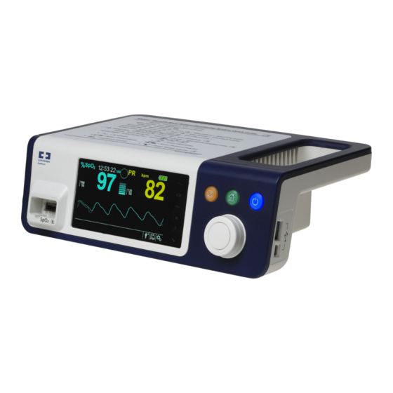
Product Views Product Views Front Panel and Display Components 2.4.1 Front and Side Panels Figure 2-1. Front and Side Panel Components Silence Alarm button Press to toggle between disabling and re-enabling the audible alarm. Reference Menu Options Navigation, p. 4-3. Return button Press to exit a menu displayed on the screen and go to the main screen. -
Page 20: Figure 2-2. Display Components
Product Overview Display Figure 2-2. Display Components Upper and lower alarm limits Reflects upper and lower SpO and pulse rate alarm limits. An alarm sounds each time patient saturation or pulse rate values violate these alarm limits. real-time value Indicates hemoglobin oxygen saturation levels. Current upper and lower alarm limit settings appear as smaller values to the left of the dynamic SpO value. - Page 21 Product Views Battery status icon Displays the battery charge remaining on an internal 5- or 10- hour battery. Charged Battery — A steady green battery icon indicates • the monitoring system is running on internal battery power and the battery is fully charged. Low Battery —...
-
Page 22: Table 2-1. Display Colors
Product Overview Patient mode area Reflects the current patient mode selected. Adult mode — Visible in the patient mode area when the • alarm limits are set to adult limit values. This is the default mode. Pediatric mode — Visible in the patient mode area when •... -
Page 23: Rear Panel
Product Views Rear Panel 2.4.2 Figure 2-3. Rear Panel Components Equipotential terminal Battery cover Nurse call port AC power connector Product and Carton Label Symbols 2.4.3 Table 2-2. Symbol Descriptors Symbol Description Symbol Description Type BF Data port Equipotentiality Date of manufacture Prescription only device Keep dry Attention, consult accompanying Fragile... - Page 24 Product Overview Table 2-2. Symbol Descriptors (Continued) Symbol Description Symbol Description Temperature limitations Manufacturer This side up EU representative Proper waste disposal for electrical and Must consult instructions for use electronic equipment Protection against fluid ingress Operator’s Manual...
-
Page 25: Installation
3 Installation Overview This chapter contains information for the installation and set up of the Nellcor™ bedside SpO patient monitoring system prior to first-time usage. Safety Reminders WARNING: Ensure the speaker is clear of any obstruction. Failure to do so could result in an inaudible alarm tone. -
Page 26: Unpacking And Inspection
Installation Caution: Follow local government ordinances and recycling instructions regarding disposal or recycling of device components, including its accessories. Unpacking and Inspection The monitoring system is shipped in a single carton. Examine the carton carefully for evidence of damage. Contact Covidien Technical Services immediately if the carton appears damaged. Do not return all packing material and the monitoring system prior to contacting Covidien. -
Page 27: Setup
Setup Setup WARNING: In the USA, do not connect to an electrical outlet controlled by a wall switch, since this increases the risk of AC power loss to the monitoring system. Caution: The monitoring system must be connected to an appropriate power source. ... -
Page 28: Using The Internal Battery
Installation Check the power/ mains outlet. Ensure the internal battery is properly installed and charged. Contact a qualified service technician or a local supplier for assistance. Using the Internal Battery 3.4.2 WARNING: The amount of time between the low battery alarm and power off becomes shorter as the battery accumulates charge/discharge cycles. -
Page 29: Connecting A Nellcor™ Pulse Oximetry Sensor
Setup Setting for SatSeconds™ is ON • Experiencing no alarm condition • Operating at ambient temperature of 25°C (±5°C) • Note: Two types of battery are available: the standard 5- hour and optional 10-hour. Note: Even if the monitoring system is turned off, the Battery Charge Indicator remains lit while the battery recharges. -
Page 30: Figure 3-1. Connecting A Pulse Oximetry Sensor To Interface Cable
Installation WARNING: Failure to cover the applied pulse oximetry sensor with opaque material while operating under high ambient light conditions may result in inaccurate measurements. Caution: For best product performance and measurement accuracy, use only accessories supplied or recommended by Covidien. -
Page 31: Operation
4 Operation Overview This chapter identifies methods for viewing and collecting patient oxygen saturation data using the Nellcor™ bedside SpO patient monitoring system. Before operating the monitoring system, thoroughly read this manual. Safety Reminders WARNING: The monitoring system is intended only as an adjunct in patient assessment. It must be used in conjunction with clinical signs and symptoms. -
Page 32: User Interface
Operation WARNING: Do not use damaged pulse oximetry sensors. Do not use with exposed optical components. Do not immerse completely in water, solvents, or cleaning solutions, since pulse oximetry sensors and connectors are not waterproof. Do not sterilize by irradiation, steam or ethylene oxide. Refer to the cleaning instructions in the Instructions for Use for reusable sensors. -
Page 33: Turning Off The Monitoring System
Menu Options Navigation Figure 4-1. Sample Initial Screen Ensure the POST pass tone sounds when POST completes. Note: Do not use the monitoring system should a repeating, high-pitched alarm tone occur at power on. Instead, please contact Technical Services or a qualified service technician. Turning off the Monitoring System 4.3.2 After using the monitoring system, turn it off safely. -
Page 34: Figure 4-2. Save Change Screen
Operation Silence Alarm button — Press this orange button for less than two (2) seconds to disable or re- enable audible alarms. This button illuminates at power on and remains lit until power off. Rotate or press the jog dial to navigate among various portions of the screen and to select menu items. -
Page 35: Menu Structure
Menu Options Navigation Menu Structure 4.4.1 Table 4-1. Menu Structure and Available Options Item Available selections Default QUICK ACCESS ALARM LIMITS menus menu SatSeconds™ alarm management setting (Off, 10, 25, 50, 100) Upper (21-100) SpO alarm limit Depends on patient mode. Lower (20-99) SpO alarm limit Reference Alarm Inhibition for SpO... -
Page 36: Quick Access Menus
Operation QUICK ACCESS Menus 4.4.2 For quick access to alarm limit settings, use the menu options listed here. Menu — Provides access to SpO alarm limit settings, alarm inhibition, and SatSeconds™ alarm management option. Reference ALARM/LIMITS Menu, p. 4-10, for basic information. The adult default setting for the SatSeconds™... -
Page 37: Options Menu
Menu Options Navigation Rotate the jog dial until reaching the desired field. Available SpO alarm limit thresholds • SatSeconds™ alarm management values include OFF, 10, 25, 50, 100. The default value is 100. Reference – SatSeconds™ Alarm Management Feature, p. 10-5. Upper and lower SpO alarm limit thresholds –... -
Page 38: Figure 4-5. Volume Selection
Operation Figure 4-5. Volume Selection Press the jog dial to access Alarm Volume, Key Beep Volume, or Pulse Volume. Alarm Volume controls the volume (1-8) of alarms. • Key Beep Volume controls the volume (0ff, 1-7) of any button press. • Pulse Volume controls the volume (0ff, 1-7) of the plethysmographic waveform. •... -
Page 39: Figure 4-7. Response Mode Menu
Menu Options Navigation pulse rate, nor does it influence the recording of trend data which occurs at one-second intervals. The default setting is the Normal Response Mode. To set response mode: Access the OPTIONS Menu. Rotate the jog dial to highlight MODE. Press the jog dial to select Normal or Fast response mode. -
Page 40: Alarm/Limits Menu
Operation Figure 4-8. Delete All Trend Data Menu Item At the prompt “Are you sure you want to delete all trend data?” choose one of the following options. Press the jog dial to select NO and keep all trend data. • Rotate the jog dial to select YES, then press to delete all trend data. •... -
Page 41: Figure 4-9. Alarm/Limits Menu Options
Menu Options Navigation Changes to the SpO and pulse rate (PR) alarm thresholds appear in their respective numerical area. In addition, caregivers may choose to use the SatSeconds™ alarm option to manage the frequency of SpO alarm limit violations by adjusting the SatSeconds™ setting. The higher the value, the less frequent the alarm. -
Page 42: Patient Mode Menu
Operation Rotate the jog dial to change the desired option value. Reference Menu Structure, p. 4-5, for adult, pediatric, and neonate limit options. Available SpO alarm limit thresholds • Upper and lower SpO alarm limit thresholds – alarm inhibition to disable audible alarms for SpO limit violations –... -
Page 43: Spo 2 Waveform Menu
Menu Options Navigation Adult: Use for adults. Pediatric: Use for children. Neonatal: Use for newborns. Press the jog dial to save the desired mode. Press the RETURN button to exit PATIENT MODE. WAVEFORM Menu 4.4.6 Caregivers may choose to set sweep speed of the plethysmographic waveform and opt to view the tabular or graphical trend screen. -
Page 44: Managing Alarms And Alarm Limits
Operation Sweep Speed — Access to set the speed at which the SpO waveform trace moves across the • screen. The higher the sweep speed value, the more data appears on the screen. Sweep Speed options are 6.25 mm/s, 12.5 mm/s and 25.0 mm/s. Tabular Trend —... -
Page 45: Audible Alarm Indicators
Managing Alarms and Alarm Limits Table 4-2. Alarm Conditions Priority Rate Color Messages High Sounds every 4 s Loss of Pulse Steady message, Critically Low-Battery condition Fast flashing numeric Medium Sounds every 8 s Yellow High Pulse Rate limits violated Steady message, Low Pulse Rate limits violated Slow flashing numeric High SpO... -
Page 46: Visual Alarm Indicators
Operation set one of the listed alternate periods as an institutional default, have a qualified service technician set the desired period via the SERVICE Menu. Note: Alarm delays should not exceed 10 seconds other than as specified in this manual. Table 4-3. Audio Status Alarm icon Status... -
Page 47: Factory Defaults
Factory Defaults Factory Defaults The monitoring system ships with factory default settings. To set different institutional default settings, contact a qualified service technician. Table 4-4. Parameter Ranges and Factory Defaults Parameter Ranges/selection Factory default Adult Pediatric Neonatal %SpO upper alarm limit 21 to 100% (1% steps) 100% %SpO... -
Page 48: Maintenance Reminder
Operation Table 4-4. Parameter Ranges and Factory Defaults (Continued) Parameter Ranges/selection Factory default Adult Pediatric Neonatal Baud rates: 19200, 38400, 57600, 115200 bps 19200 bps Trend data download settings Protocol: ASCII 1, ASCII 2 ASCII 1 Nurse call settings: NORMALLY +, NORMALLY –... -
Page 49: Data Management
5 Data Management Overview This chapter contains information for accessing patient trend data obtained using the Nellcor™ bedside SpO patient monitoring system. Trend data can be viewed anytime patient trend is stored in the monitoring system. The monitoring system stores up to 96 hours of trend data. When the monitoring system begins measuring vital signs, it saves data every four (4) seconds. -
Page 50: Graphical Trend Data
Data Management Select Tabular Trend. To scroll through Tabular Trend Data: Rotate the jog dial to scroll through the trend data. Clockwise rotation moves forward to newer data. • Counterclockwise rotation moves backward to older data. • Press the jog dial again to adjust the scroll granularity. Larger values scroll through more data faster. ... -
Page 51: External Data Communication
External Data Communication To scroll through Graphical Trend Data: Rotate the jog dial to highlight Scroll. Press the jog dial to activate scrolling. Rotate the jog dial to scroll through the trend data. Clockwise rotation moves forward to newer data. •... -
Page 52: Figure 5-3. Nurse Call Interface Pin Layout
Data Management Note: Communication (Nurse Call Interface) is limited to inside a single institution. The nurse call feature of the monitoring system works in conjunction with the nurse call system of the institution when the monitoring system sounds an audible alarm. It is operational regardless of whether the monitoring system uses AC power or battery power, as long as a proper connection between the nurse call port and the host system exists. -
Page 53: Trend Data Download
External Data Communication Table 5-1. Nurse Call Relay Pins States for NORMALLY + Monitoring system ON Monitoring system OFF NORMALLY + No alarm Audible alarm or alarm silenced Pin 1 and Pin 2 Open Closed Closed Pin 2 and Pin 3 Closed Open Open When the nurse call polarity is set to NORMALLY –, the nurse call relay operation is as follows:... - Page 54 Data Management Note: Users may choose to import patient trend data to a spreadsheet program. To do so, users must export trend data using the ASCII 2 format option. Have a qualified service technician set this option prior to attempting a data download.
-
Page 55: Figure 5-4. Trend Data Download Option
External Data Communication Figure 5-4. Trend Data Download Option Press the jog dial to access the TREND DATA DOWNLOAD Menu. Connect a mini-USB cable from the monitoring system to the computer. Grasp the mini-USB end of the cable. Firmly insert into the bottom mini-USB data port. Firmly insert the USB end of the cable into a USB port on the host system. -
Page 56: Figure 5-5. Trend Data Download Status
Data Management Figure 5-5. Trend Data Download Status Confirm the monitoring system is sending trend data to a personal computer (PC) by observing the computer screen for a scrolling trend data record. If no trend data values appear, check connectivity and ensure the personal computer contains HyperTerminal™* software. If this is all operational, verify patient trend data history exists on the monitoring system. - Page 57 External Data Communication Note: If the personal computer is not connected via the USB to mini-USB cable to the monitoring system, the proper COM port option will not appear in the list. When the Connect To window opens, find the CONNECT USING option and click the down arrow to identify possible modem options.
-
Page 58: Figure 5-6. Sample Trend Data Printout
Data Management Figure 5-6. Sample Trend Data Printout Product column headings Data source, firmware version, and system settings Patient data column headings Lists appropriate time and data headings Time column Real-time clock date and time stamp Output Complete Message indicating completion of trend data download %SpO Current saturation value Current pulse rate... -
Page 59: Figure 5-7. Sample Bridge Driver Installer Window
External Data Communication Note: The following graphics are representative of the screens users may encounter while installing a USB driver from the compact disc. Individual operating system languages may vary. To install a USB driver from the compact disc Insert the Nellcor™... -
Page 60: Figure 5-8. Sample New Hardware Wizard Screen
Data Management Figure 5-8. Sample New Hardware Wizard Screen At the prompt from the installer, click on the NEXT button to copy the driver to the PC. When the installer provides the end-user license agreement, read it carefully, then click the button for accepting the terms of the license. -
Page 61: Figure 5-9. Sample Device Manager Button Under Hardware Tab
External Data Communication Figure 5-9. Sample DEVICE MANAGER Button Under Hardware Tab Select the Ports option from the resulting list. Operator’s Manual 5-13... -
Page 62: Figure 5-10. Sample Hardware List In Device Manager Window
Data Management Figure 5-10. Sample Hardware List in Device Manager Window Double click the Silicon Labs CP210x USB to UART Bridge option. Note: The listed COM port should match the HyperTerminal™* COM port designation. Reference To launch HyperTerminal™*:, p. 5-8. 5-14 Operator’s Manual... -
Page 63: Figure 5-11. Sample Initial Usb To Uart Bridge Properties Window
External Data Communication Figure 5-11. Sample Initial USB to UART Bridge Properties Window Click the Port Settings tab. Set the bits per second to one of four possible baud rates: 19200, 38400, 57600, or 115200. The factory default is 19200 bps. Operator’s Manual 5-15... -
Page 64: Firmware Upgrades
Data Management Figure 5-12. Sample Baud Rate List Under Port Settings Tab Click the OK button to complete the process. Reference To download trend data, p. 5-6, and proceed to step 8, utilizing HyperTerminal™* to connect to the monitoring system. Firmware Upgrades 5.4.3 Contact a qualified service technician to perform any firmware upgrade to the monitoring system, as described in the Service Manual. -
Page 65: Performance Considerations
6 Performance Considerations Overview This chapter contains information about optimizing the performance of the Nellcor™ bedside patient monitoring system. Verify the performance of the monitoring system by following the procedures outlined in the Service Manual. Have a qualified service technician perform these procedures prior to initial installation in a clinical setting. -
Page 66: Patient Conditions
Performance Considerations perform these procedures prior to initial installation in a clinical setting and every 24 months as part of preventive maintenance. Reference Service, p. 7-4. Patient Conditions 6.3.2 Application issues and certain patient conditions can affect the measurements of the monitoring system and cause the loss of the pulse signal. - Page 67 Performance Considerations WARNING: Use only Covidien-approved pulse oximetry sensors and pulse oximetry cables when connecting to the sensor connector. Connecting any other cable or sensor influences the accuracy of sensor data, since this may lead to adverse results. WARNING: Failure to cover the pulse oximetry sensor site with opaque material in high ambient light conditions may result in inaccurate measurements.
-
Page 68: Reducing Emi (Electromagnetic Interference)
Performance Considerations the performance of a Nellcor™ pulse oximetry sensor. To prevent interference from ambient light, ensure that the sensor is properly applied, and cover the sensor site with opaque material. If patient activity presents a problem, try one or more of the following remedies to correct the problem. Verify the Nellcor™... -
Page 69: Obtaining Technical Assistance
Obtaining Technical Assistance Because of the proliferation of radio frequency transmitting equipment and other sources of electrical noise in health care environments (for example, electrosurgical units, cellular phones, mobile two-way radios, electrical appliances, and high-definition television), it is possible that high levels of such interference due to close proximity or strength of a source may result in disruption of monitoring system performance. - Page 70 Performance Considerations Page Left Intentionally Blank Operator’s Manual...
-
Page 71: Preventive Maintenance
7 Preventive Maintenance Overview This chapter describes the steps required to maintain, service, and properly clean the Nellcor™ bedside SpO patient monitoring system. Cleaning WARNING: Do not spray, pour, or spill any liquid on the monitoring system, its accessories, connectors, switches, or openings in the chassis. -
Page 72: Recycling And Disposal
Preventive Maintenance Recycling and Disposal When the monitoring system, battery, or accessories reach the end of useful life, recycle or dispose of the equipment according to appropriate local and regional regulations. Battery Maintenance WARNING: Explosion hazard — Do not use the battery with other manufacturer's batteries, different types or models of batteries such as dry batteries, nickel-metal hydride batteries, or Lithium-ion batteries together. -
Page 73: Periodic Safety Checks
Periodic Safety Checks Caution: Do not mistreat the battery, or use the battery in applications not recommended by Covidien. Caution: Keep the battery out of reach of children to avoid any accidents. Caution: If there are any problems with the battery, immediately put the monitoring system in a safe place and contact a qualified service technician. -
Page 74: Service
Preventive Maintenance Service WARNING: Only a qualified service technician should remove the cover or access any internal components. Caution: Dispose of monitoring system in accordance with local requirements and regulations. The monitoring system requires no routine service other than cleaning, battery maintenance, and service activity mandated by the institution. -
Page 75: Troubleshooting
8 Troubleshooting Overview This chapter describes how to troubleshoot common problems while using the Nellcor™ bedside SpO patient monitoring system. General WARNING: Check the patient's vital signs by alternate means should there be any doubt about the accuracy of any measurement. Request a qualified service technician confirm the monitoring system is functioning correctly. -
Page 76: Error Conditions
Troubleshooting Error Conditions Table 8-1. Common Problems and Resolutions Problem Resolution Battery Charging Indicator not lit Check power cord Check battery Check AC power inlet Check power/ mains outlet Sensor Message Reference Performance Considerations, p. 6-1. Check patient status; keep patient still, check for perfusion Pulse search Check all connections Signal Artifact Detected... - Page 77 Error Conditions Table 8-1. Common Problems and Resolutions (Continued) Problem Resolution No sound generation Verify setting point of volume is not 0 or 1. Verify alarm setup is not set to alarm silenced. If the error continues, contact Technical Services or a qualified service technician. Abnormally shut down last time Check any temporary settings such as alarm limits, response mode, and patient mode, message...
-
Page 78: Return
Troubleshooting Reference Managing Alarms and Alarm Limits, p. 4-14, for any issues related to alarm conditions. Return Contact Covidien or a local Covidien representative for shipping instructions, including a Returned Goods Authorization (RGA) number. Reference Obtaining Technical Assistance, p. 1-5. Unless otherwise instructed by Covidien, it is not necessary to return the sensor or other accessory items with the monitoring system. -
Page 79: Accessories
9 Accessories Overview This chapter contains information for selecting the appropriate pulse oximetry sensor for use with the Nellcor™ bedside SpO patient monitoring system. Nellcor™ Pulse Oximetry Sensors WARNING: Before use, carefully read the pulse oximetry sensor Instructions for Use, including all warnings, cautions, and instructions. -
Page 80: Table 9-1. Nellcor™ Pulse Oximetry Sensor Models And Patient Sizes
Accessories Caution: Nellcor™ adhesive pulse oximetry sensors are intended for single-patient use only. Do not reuse pulse oximetry sensors. When selecting a Nellcor™ pulse oximetry sensor, consider the following items: patient’s weight and activity level, the adequacy of perfusion, and the available sensor sites, the need for sterility, and the anticipated duration of monitoring. -
Page 81: Optional Equipment
Optional Equipment Table 9-1. Nellcor™ Pulse Oximetry Sensor Models and Patient Sizes (Continued) Nellcor™ pulse oximetry sensor Patient size Nellcor™ flexible SpO sensor (reusable, large) FLEXMAX >20 kg Nellcor™ flexible SpO sensor (reusable, small) FLEXMAX-P >20 kg Nellcor™ flexible SpO sensor (reusable, large, home care) FLEXMAX-HC >20 kg Nellcor™... -
Page 82: Biocompatibility Testing
Accessories GCX wall mount arm and channel— Attaches to the adapter plate, which attaches to the arm. GCX roll stand—Attaches to the adapter plate. Covidien Technical Services: Patient Monitoring 15 Hampshire Street, Mansfield, MA 02048 USA 1.800.635.5267, 1.925.463.4635 or contact a local Covidien representative www.covidien.com Biocompatibility Testing Biocompatibility testing has been conducted on Nellcor™... -
Page 83: 10 Theory Of Operations
10 Theory of Operations Overview 10.1 This chapter explains the theory behind operations of the Nellcor™ bedside SpO patient monitoring system. Theoretical Principles 10.2 The monitoring system uses pulse oximetry to measure functional oxygen saturation in the blood. Pulse oximetry works by applying a Nellcor™ pulse oximetry sensor to a pulsating arteriolar vascular bed, such as a finger or toe. -
Page 84: Automatic Calibration
Theory of Operations diastole). By doing so, it focuses on light absorption by pulsatile arterial blood, eliminating the effects of nonpulsatile absorbers such as tissue, bone, and venous blood. Automatic Calibration 10.3 Because light absorption by hemoglobin is wavelength dependent and because the mean wavelength of LEDs varies, a monitoring system must know the mean wavelength of the pulse oximetry sensor's red LED to accurately measure SpO During monitoring, the monitoring system’s software selects coefficients that are appropriate for... -
Page 85: Unique Technologies
Unique Technologies Unique Technologies 10.5 Functional versus Fractional Saturation 10.5.1 This monitoring system measures functional saturation where oxygenated hemoglobin is expressed as a percentage of the hemoglobin that can transport oxygen. It does not detect significant amounts of dysfunctional hemoglobin, such as carboxyhemoglobin or methemoglobin. -
Page 86: Data Update Period, Data Averaging, And Signal Processing
Theory of Operations Figure 10-1. Oxyhemoglobin Dissociation Curve % Saturation Axis Increased pH; Decreased temperature, PCO , and 2,3-DPG (mmHg) Axis Decreased pH; Increased temperature, PCO , and 2,3-DPG Data Update Period, Data Averaging, and Signal Processing 10.5.3 The advanced signal processing of the OxiMax™ algorithm automatically extends the amount of data required for measuring SpO and pulse rate depending on the measurement conditions. -
Page 87: Satseconds™ Alarm Management Feature
SatSeconds™ Alarm Management Feature SatSeconds™ Alarm Management Feature 10.6 The monitoring system monitors the percentage of hemoglobin binding sites saturated with oxygen in the blood. With traditional alarm management, upper and lower alarm limits are set to alarm at specific SpO levels. -
Page 88: Second Spo 2 Event
Theory of Operations Figure 10-3. First SpO Event: No SatSeconds™ Alarm Second SpO Event 10.6.2 Consider the second event. Suppose the SatSeconds™ alarm limit is still set to 25. The patient’s drops to 84% and the duration of the event is 15 seconds before saturation again exceeds the lower alarm threshold of 85%. -
Page 89: Third Spo 2 Event
SatSeconds™ Alarm Management Feature Figure 10-4. Second SpO Event: No SatSeconds™ Alarm Third SpO Event 10.6.3 Consider the third event. Suppose the SatSeconds™ alarm limit is still set to 25. During this event, the patient’s SpO drops to 75%, which is 10% below the lower alarm threshold of 85%. Since the patient’s saturation does not return to a value over the lower alarm threshold within 2.5 seconds, an alarm sounds. -
Page 90: The Satseconds™ Safety Net
Theory of Operations Figure 10-5. Third SpO Event: Triggers SatSeconds™ Alarm The SatSeconds™ Safety Net 10.6.4 The SatSeconds™ “Safety Net” is for patients with saturation levels frequently below the limit, but not staying below the limit long enough for the SatSeconds™ time setting to be reached. When three or more limit violations occur within 60 seconds, an alarm sounds even if the SatSeconds™... -
Page 91: 11 Product Specifications
11 Product Specifications Overview 11.1 This chapter contains physical and operational specifications of the Nellcor™ bedside SpO patient monitoring system. Ensure all product requirements are met prior to installation of the monitoring system. Physical Characteristics 11.2 Enclosure Weight 1.6 kg (3.5 lbs.) including battery Dimensions 255 ×... -
Page 92: Electrical
Product Specifications Electrical 11.3 Battery power requirement AC 100-240VAC, 50/60Hz, 45 VA 10.8 V/ 2200 mAh Voltage and capacity of Li-Ion, 5 hour 10.8 V/4400 mAh Voltage and capacity of Li-Ion, 10hour Compliance 91/157/EEC Fast-acting fuse 2A 32VAC,/DC Fast-acting fuse 500 mA 32VAC/50DC New batteries typically provide the stated duration when operating in Normal Response Mode, with pulse beep, the SatSeconds™... -
Page 93: Tone Definition
Tone Definition Tone Definition 11.5 Table 11-2. Tone Definitions Tone category Description High priority alarm tone Volume level Adjustable (level 1-8) Pitch (± 20Hz) 976 Hz Pulse width (± 20msec) 150 msec (IEC60601-1-8) Number of pulses in burst 10, interburst interval of 4 sec (IEC60601-1-8) Repetitions Continually Medium priority alarm tone... -
Page 94: Performance Specifications
Product Specifications Table 11-2. Tone Definitions (Continued) Tone category Description Number of pulses Repetitions No repeat POST pass tone Volume level Not changeable Pitch (± 20Hz) 813 Hz Pulse width (± 20msec) 1500 msec Number of pulses Repetitions No repeat Performance Specifications 11.6 Table 11-3. Trends Types... -
Page 95: Sound Pressure
Sound Pressure Table 11-4. Pulse Oximetry Sensor Accuracy and Ranges Range type Range values Measurement ranges saturation range 1% to 100% Pulse rate range 20 to 250 beats per minute (bpm) Perfusion range 0.03% to 20% Display sweep speed 6.25 mm/sec, 12.5 mm/sec, 25.0 mm/sec Measurement accuracy Pulse rate accuracy 20 to 250 beats per minute (bpm) ±3 digits... -
Page 96: Product Compliance
Product Specifications Product Compliance 11.8 Standards compliance EN ISO 80601-2-61: Edition 1.0 EN IEC 60601-1: Edition 3.1 EN IEC 60601-1-2: Edition 3.0 and 4.0 EN IEC 60601-1-6: Edition 3.1 EN IEC 60601-1-8: Edition 2.1 EN IEC 60601-1-11: Edition 2.0 CAN/CSA C22.2 No. 60601-1:14 3rd Edition ANSI/AAMI ES 60601-1:2005/(R)2012 Equipment classifications Type of protection against electric shock... -
Page 97: Table 11-6. Electromagnetic Emissions Guidelines
Manufacturer’s Declaration Caution: For best product performance and measurement accuracy, use only accessories supplied or recommended by Covidien. Use accessories according to the Instructions for Use. Use only accessories that have passed the recommended biocompatibility testing in compliance with ISO10993-1. -
Page 98: Table 11-7. Electromagnetic Immunity Guidelines
Product Specifications Electromagnetic Immunity Note: These guidelines may not apply in all situations. Electromagnetic propagation is affected by absorption and reflection from structures, objects, and people. Table 11-7. Electromagnetic Immunity Guidelines Immunity IEC/EN 60601-1-2 Compliance Electromagnetic environment test test level level guidance Electrostatic ±... -
Page 99: Table 11-8. Recommended Separation Distances
Manufacturer’s Declaration Table 11-8. Recommended Separation Distances Immunity IEC/EN 60601-1-2 Compliance Electromagnetic test test level level environment guidance Frequency of Equation for separation transmitter distance (d) Conducted RF 3 Vrms 3 Vrms 1.2 P 150 kHz 150 kHz IEC/EN 61000-4-6 80 MHz 80 MHz 150 kHz to 80 MHz 6 Vrms ISM bands... -
Page 100: Table 11-9. Test Specifications For Enclosure Port Immunity To Rf Wireless Communications Equipment
Product Specifications Table 11-9. Test Specifications for Enclosure Port Immunity to RF Wireless Communications Equipment Test Band Service Modulation Max. power Distance Immunity frequency (MHz) test level (MHz) (V/m) 380 to 390 TETRA 400 Pulse modulation 18 Hz 430 to 470 GMRS 460, FRS 460 ±... -
Page 101: Sensor And Cable Compliance
Manufacturer’s Declaration Sensor and Cable Compliance 11.9.2 WARNING: The use of accessories, sensors, and cables other than those specified may result in inaccurate readings of the monitoring system and increased EMI emissions and decreased electromagnetic immunity of the monitoring system. Table 11-10. Cables and Sensors Item Maximum length... -
Page 102: Table 11-11. Earth Leakage And Touch Current
Product Specifications Table 11-11. Earth Leakage and Touch Current Earth leakage current IEC 60601-1 Neutral ANSI/AAMI ES 60601-1 Condition AC line polarity Line cord line cord Normal Normal Closed Closed 5 mA Single fault Open Closed 10 mA Closed Open Normal Reversed Closed Closed 5 mA... -
Page 103: Table 11-12. Patient Leakage Current
Manufacturer’s Declaration Table 11-12. Patient Leakage Current Patient leakage current IEC 60601-1 ANSI/AAMI Power line ground ES 60601-1 Condition AC line polarity Neutral line cable Normal Normal Closed Closed 100 µA Single fault Open Closed 500 µA Closed Open Normal Reversed Closed Closed 100 µA Single fault... -
Page 104: Essential Performance
Product Specifications Essential Performance 11.10 Per IEC 60601-1 and ISO 80601-2-61, the monitoring system’s essential performance attributes include: and pulse rate accuracy — Reference Table 11-4, Pulse Oximetry Sensor Accuracy and Ranges • on p. 11-5. Audible indicators — Reference Managing Alarms and Alarm Limits, p. -
Page 105: Overview
A Clinical Studies Overview This appendix contains data from clinical studies conducted for the Nellcor™ sensors used with the Nellcor™ bedside SpO patient monitoring system. One (1) prospective, controlled hypoxia clinical study was conducted to demonstrate the accuracy of Nellcor™ sensors when used in conjunction with the Nellcor™ bedside SpO patient monitoring system. -
Page 106: Study Population
Clinical Studies Study Population Table A-1. Demographic Data Type Class Total Male Gender Female Caucasian Hispanic Race African American Asian 19-48 Weight 108-250 Very light Olive Skin pigment Dark olive/Medium black Extremely dark/Blue black Study Results Accuracy was calculated using the root mean square difference (RMSD). Table A-2. SpO Accuracy for Nellcor™... -
Page 107: Adverse Events Or Deviations
Adverse Events or Deviations Figure A-1. Modified Bland-Altman Plot Test sensor; Avg CO-oximeter value 70-100% SpO Avg CO-oximeter value 70-100% SpO Oximetry board with MAX-A sensor Trendline of MAX-A sensor Oximetry board with MAX-N sensor Trendline of MAX-N sensor Oximetry board with MAX-FAST sensor Trendline of MAX-FAST sensor Adverse Events or Deviations The study was conducted as expected with no adverse events and no deviations from the... -
Page 108: Conclusion
Clinical Studies Conclusion The pooled results indicate that for a saturation range of 60-80% for SpO , the acceptance criterion was met for the monitoring system when tested with MAX-A, MAX-N and MAX-FAST sensors. The pooled results indicate that for a saturation range of 70-1 00% for SpO , the acceptance criterion was met. - Page 109 Index Battery charge 2-5, 3-3, 3-5 Interference 2-5 Alarm limits menu icon 2-5 Sensor disconnect 2-5 Alarm Silenced 4-16 Sensor message 2-5 Anemia 6-2 Sensor off 2-5 Intended Use 2-2 Biocompatibility Testing 9-4 Button Measured Saturation 10-3 Power 2-3 Message, Sensor 3-6 Return 2-3 Monitoring system Silence Alarm 2-3...
- Page 110 Atmospheric pressure 2-7 Attention 2-7 CE mark 2-7 Data port 2-7 Date of manufacture 2-7 Equipotentiality 2-7 EU representative 2-8 Fragile 2-7 Humidity limitations 2-7 Keep dry 2-7 Manufacturer 2-8 Prescription only 2-7 Temperature limitations 2-8 This side up 2-8 Type BF 2-7 UL listed 2-7 Tabular Trend Data 5-2...
- Page 112 Part No. PT00093073 Rev B (A7213-3) 2018-12 COVIDIEN, COVIDIEN with logo, and Covidien logo and Positive Results for Life are U.S. and internationally registered trademarks of Covidien AG. ™* brands are trademarks of their respective owners. Other brands are trademarks of a Covidien company. ©...
Need help?
Do you have a question about the Nellcor Series and is the answer not in the manual?
Questions and answers
Need help troubleshooting a Nellcor Star 60 bedside monitor. Unable to find instructions or the model number
To troubleshoot a Coviden Nellcor Star 60 bedside monitor:
1. Check for Error Codes: If the system detects an error, it will display an error code. Refer to the Service Manual for details on each code.
2. Verify Measurement Accuracy: If there is doubt about any measurement, check the patient's vital signs using alternate methods.
3. Inspect System Functionality: Request a qualified service technician to confirm the system is working properly.
4. Do Not Open the Device: Only a qualified service technician should remove the cover or access internal components.
5. Refer to the Operator’s Manual: Use the manual for basic troubleshooting steps and understanding system functions.
6. Contact Technical Services: If further help is needed, contact Technical Services or a qualified technician.
The system requires no calibration and only routine maintenance like cleaning and battery checks.
This answer is automatically generated