Table of Contents
Advertisement
Quick Links
Utilitech and UT Design® and Grounded in Quality® are
registered trademarks of LF, LLC. All Rights Reserved.
ATTACH YOUR RECEIPT HERE
Serial Number:
Questions, problems, missing parts? Contact the customer service department at
1-866-994-4148, 8 a.m. - 6 p.m., EST, Monday - Thursday, 8 a.m. - 5 p.m., EST, Friday.
AB15502
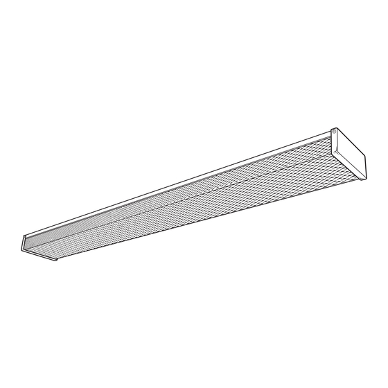
4 FT. 2-LIGHT WRAP LIGHT
Purchase Date:
1
ITEM #0749980
MODEL #LF1054-WH1-48T82-U
Français p. 8
Español p. 15
Advertisement
Table of Contents

Subscribe to Our Youtube Channel
Related Manuals for Utilitech LF1054-WH1-48T82-U


Summary of Contents for Utilitech LF1054-WH1-48T82-U
- Page 1 ITEM #0749980 4 FT. 2-LIGHT WRAP LIGHT MODEL #LF1054-WH1-48T82-U Utilitech and UT Design® and Grounded in Quality® are registered trademarks of LF, LLC. All Rights Reserved. Français p. 8 Español p. 15 ATTACH YOUR RECEIPT HERE Serial Number: Purchase Date: Questions, problems, missing parts? Contact the customer service department at 1-866-994-4148, 8 a.m.
- Page 2 PACKAGE CONTENTS PART DESCRIPTION QUANTITY PART DESCRIPTION QUANTITY Fixture Pan End Cap Socket Spring Diffuser Ground Wire HARDWARE CONTENTS (shown actual size) Wire Nut Short Wood Screw Drywall Anchor Support Chain Machine Screw Qty. 3 Qty. 2 Qty. 2 Qty. 2 Qty.
- Page 3 ASSEMBLY INSTRUCTIONS With power disconnected to the electrical box, remove the old fixture. If the old fixture is attached to an electrical box having more that has two (2) wire leads, use tape and markings to keep track of which wires were attached together. 1.
- Page 4 ASSEMBLY INSTRUCTIONS 5. Pull the fixture wires through the hole in the center of the fixture pan (A) to the backside of the fixture. Using the support chain (EE), connect one end to the back of the fixture pan near the center in the specially designed slots and hook the other end to the mounting ears on the electrical box.
- Page 5 ASSEMBLY INSTRUCTIONS 8. CEILING JOIST MOUNTING: While holding the fixture pan (A) in line with the pilot holes, drive the wood screws (CC) into the wooden studs. Tighten until the fixture pan (A) has been secured to the mounting surface. DRYWALL MOUNTING: For mounting into drywall, hold the fixture pan (A) in line with the drywall anchors (DD) that were installed in step 4 and drive the wood screws (CC)
- Page 6 ASSEMBLY INSTRUCTIONS 12. At the other end of the fixture, pull back on the end cap (D) equipped with the spring (E) until that end of the diffuser (C) clears. Raise the diffuser (C) into place until the diffuser (C) seats and carefully release the end cap, which will pivot back in place and securely hold the diffuser (C).
- Page 7 CARE AND MAINTENANCE Periodically clean the fixture using a mild, non-abrasive soap based cleaner and soft cotton cloth. Do NOT use solvents, cleaners containing abrasive agents, ammonia, or surfactants. When cleaning the fixture, make sure you have the power turned off and do not spray liquid cleaner directly onto the diffuser, bulb, socket, ballast, or wiring.
Need help?
Do you have a question about the LF1054-WH1-48T82-U and is the answer not in the manual?
Questions and answers