Table of Contents
Advertisement
Available languages
Available languages
Quick Links
Advertisement
Chapters
Table of Contents

Related Manuals for honle UV-Scan

Summary of Contents for honle UV-Scan
- Page 1 Betriebsanleitung UV-Scan UV-Scan mit Akku tesa UV Strips UV-Scan PC-Software...
- Page 2 UV-Scan Impressum Alle Rechte vorbehalten Copyright by Dr. Hönle AG Lochhamer Schlag 1, 82166 Gräfelfing / München Printed in Germany, Oktober 16 Diese Betriebsanleitung darf – auch auszugsweise – nur mit ausdrückli- cher, schriftlicher Genehmigung durch die Dr. Hönle AG nachgedruckt oder sonst wie vervielfältigt werden.
-
Page 3: Table Of Contents
2.2. Verpflichtung des Personals ..............8 2.3. Bestimmungsgemäße Verwendung ............8 2.4. Besondere Hinweise bei UV-Scan mit integriertem Akku ..... 9 2.5. Gewährleistung und Haftung ..............9 2.6. Wartung und Beheben von Störungen ..........10 3. Transport, Lagerung, Lieferung .............. 11 Lieferumfang .................... - Page 4 UV-Scan 12. UV-Scan mit Akku (opt.) ............... 26 12.1. Allgemeines ..................26 12.2. Laden des Akkus ................26 13. Wartung und Reinigung ................ 27 13.1. Kalibrierung ..................27 13.2. Reinigung .................... 27 14. Fehlermeldungen ................... 28 14.1. Fehlerhafte Streifenmessung .............. 28 14.2.
-
Page 5: Warnhinweise Und Symbole In Der Betriebsanleitung
Warnhinweise und Symbole in der Betriebsanleitung Die vorliegende Betriebsanleitung beschreibt das Geräte, seine Bedienung, seine Einsatzmöglichkeiten und die Verwendung der dazugehörigen Mess- ® streifen tesa UV Strips. Die Sicherheits- und Gefahrenhinweise erläutern eine sichere und sachgerechte Handhabung des Geräts Die nachfolgenden Symbole finden Sie bei allen Sicherheits-/ Warnhinwei- sen in dieser Betriebsanleitung, bei denen Gefahr für Personen besteht. -
Page 6: Beschreibung
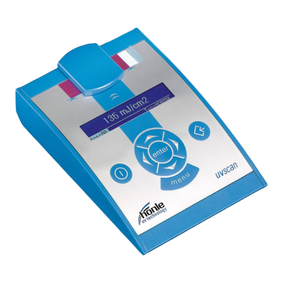
® Nach der Bestrahlung wird der tesa UV Strip vom Werkstück abgelöst und in die Auswerteeinheit UV-Scan eingelegt. Das Gerät zeigt dann innerhalb von Sekunden die Bestrahlungsdosis in mJ/cm an. Der Messwert kann ei- ner Messungsposition (Maschinennummer) zugeordnet werden und zu- sammen mit Datum, Uhrzeit und einem individuellen Kommentar im Mess- wertspeicher abgelegt werden. -
Page 7: Beschreibung Der Bedienelemente
Sub-D 9polig Stecker Stromversorgung Anschluss für mitgeliefertes Steckernetzteil. ACHTUNG! Der Hönle UV-Scan darf nur mit dem mitgelieferten Ste- ckernetzteil und den beiliegenden Zubehörteilen verwendet werden. Bei Verwendung von anderen Netzteilen oder Er- satzteilen kann der UV-Scan beschädigt werden. 035923DE-EN c... -
Page 8: Sicherheitshinweise
UV-Scan 2. Sicherheitshinweise 2.1. Allgemeine Hinweise Die Kenntnis aller grundlegenden Sicherheitsvorschriften ist die Vorausset- zung für den sicheren Umgang und den störungsfreien Betrieb des Geräts Diese Betriebsanleitung enthält die wichtigsten Hinweise, um das Gerät sicherheitsgerecht zu betreiben. Die Betriebsanleitung, insbesondere die Sicherheitshinweise, sind von allen Personen zu beachten, die mit dem Ge- rät arbeiten. -
Page 9: Besondere Hinweise Bei Uv-Scan Mit Integriertem Akku
Explosionsgefahr besteht! Auch beschädigte Akkus können explodie- ren. Wenn der Akku getauscht werden muss, schicken Sie den UV-Scan an den Hönle Kundendienst. Entsorgen Sie den UV-Scan mit integriertem Akku ordnungsgemäß oder schicken Sie den UV-Scan an den Hönle Kunden- dienst. -
Page 10: Wartung Und Beheben Von Störungen
UV-Scan 2.6. Wartung und Beheben von Störungen Im Kapitel „Wartung, Instandhaltung und Reinigung" sind alle notwendigen Wartungsarbeiten beschrieben. Deren Ausführung gewährleistet einen zu- verlässigen Betrieb. Außer den in dieser Betriebsanweisung beschriebenen Maßnahmen, dürfen keine Reparaturen oder Veränderungen an dem Gerät durchge- führt werden. -
Page 11: Transport, Lagerung, Lieferung
3. Transport, Lagerung, Lieferung Lieferumfang Folgende Einzelteile sind im Lieferumfang enthalten: Koffer UV-Scan mit: UV-Scan Messgerät (1) Steckernetzteil mit Euro- Stecker (2) Wechseladapter für Stecker- netzteil USA, UK und Australi- en, (3) Bedienungsanleitung (ohne Abb.) ... -
Page 12: Aufstellen Und Inbetriebnahme
Einschalten erst einige Zeit an die Umge- bungstemperatur angleichen. HINWEIS Da es sich bei dem UV-Scan um ein hochempfindliches optisches Messgerät handelt, sollte es nicht im direkten Sonnenlicht oder unter sehr hellen Lichtquellen ver- wendet werden, andernfalls kann es zu einer Verfäl- schung der Messergebnisse kommen. -
Page 13: Stromversorgung
2. Steckernetzteil in Netzversor- gung einstecken. ACHTUNG! Der Hönle UV-Scan darf nur mit dem mitgelieferten Ste- ckernetzteil und den beiliegenden Zubehörteilen verwendet werden. Bei Verwendung von anderen Netzteilen oder Er- satzteilen kann der UV-Scan beschädigt werden. Garantieansprüche sind für diesen Fall ausgeschlossen. -
Page 14: Verwendung Der Tesa Uv Strips
UV Strips eignen sich zur präzisen und schnellen UV- Dosismessung. Die Streifen messen die auf ihre Oberfläche einwirkende Energiedichte in mJ/cm . Die UV-Strahlung führt zu einer Rotfärbung des Streifenmaterials und kann mit dem UV-Scan Messgerät ausgewertet und angezeigt werden. ® 5.1. Technische Daten des tesa... -
Page 15: Anwendung Der Tesa Uv Strips
® 5.2. Anwendung der tesa UV Strips Die tesa UV Strips werden in einer speziellen lichtundurchlässigen Folien- verpackung geliefert und sollten aus dieser erst unmittelbar vor der Ver- wendung entnommen werden. Die Streifen sind gegenüber dem Tageslicht sehr unempfindlich, verfärben sich aber nach längerer Zeit auch dadurch. ®... -
Page 16: Hinweise Für Reproduzierbare Messergebnisse
UV-Scan 5.3. Hinweise für reproduzierbare Messergebnisse ® 5.3.1. Informationen von tesa SE zur Vorkonditionierung ® Die tesa UV Strips werden mit sehr sensiblen, reaktiven Rohstoffen aus- gestattet. Für eine Reproduzierbarkeit der gemessen Werte ist die Einhal- tung der richtigen Methodik und eine optimale Vorkonditionierung der Messstreifen zu gewährleisten. - Page 17 Maximaldosis des Streifens ® Der tesa UV Strip darf nur im angegebenen Messbereich verwendet wer- den. Ein zu hoher Dosiseintrag führt zu fehlerhaften Messergebnissen. Es erscheint im Display eine entsprechende Warnmeldung. Beachten Sie auch die Angaben im Diagramm „Empfohlene Mindestbahngeschwindigkeit“. Außerhalb dieser Spezifikation ist nicht mit reproduzierbaren Ergebnissen zu rechnen.
-
Page 18: Grundfunktionen Des Hönle Uv-Scan
UV-Scan 6. Grundfunktionen des Hönle UV-Scan 6.1. UV-Scan ein-/ausschalten UV-Scan einschalten Durch Drücken der Taste An/Aus schaltet sich der UV-Scan ein. Es erscheint nach kurzer Zeit der Startbildschirm. Auf diesem kann die Seriennummer und die aktuelle Versi- onsnummer der Software abgelesen werden Das Gerät durchläuft nach jedem Start... -
Page 19: Relativwertanzeige
7. Relativwertanzeige Mit dem UV-Scan ist es möglich, den aktuellen Messwert auch als Relativ- wert in Bezug zu einem vorher festgelegten Referenzwert anzuzeigen. Im Display erscheint dann neben dem Ergebnis in mJ/cm auch der Prozent- wert in Bezug zur Referenz. -
Page 20: Messpositionen
UV-Scan 8. Messpositionen Im UV-Scan können bis zu 100 Messpositionen gespeichert werden. Jeder Messwert kann einer Messposition zugeordnet werden. Dies hat für die Verwendung des Gerätes folgende Vorteile: Alle Messungseinstellungen (Streifentyp, Referenzwert) werden bei Auswahl der Messposition automatisch voreingestellt ... -
Page 21: Name Für Messposition Vergeben
8.2. Name für Messposition vergeben Zur leichteren Identifizierung der Messposition kann jeder Positionsnummer noch ein Name zugeordnet werden. Hierfür stehen 10 Zeichen zur Verfü- gung. Gewünschte Messposition ein- stellen (siehe Kapitel 8.1) Mit den Cursortasten das Feld „Name“ auswählen und neuen Namen eingeben 8.3. -
Page 22: Messwertspeicher
UV-Scan 9. Messwertspeicher Der UV-Scan verfügt über einen integrierten Messwertspeicher mit insgesamt 400 Speicherplätzen. Auf jedem Speicherplatz werden folgende Informationen gespeichert: Messwert in mJ/cm Kommentar (2 Zeilen) Datum und Uhrzeit Streifentyp Fortlaufende Messungsnummer Referenzwert ... -
Page 23: Messwerte Als Grafik Anzeigen
3. Mit den Cursortasten die entsprechende Auswahl treffen Es können alle Messwerte aus dem Speicher angezeigt werden oder nur die einer bestimmten Messposition. Die Messwerte werden als Liste dargestellt. Mit den Cursortasten kann nach oben und unten gescrollt werden. Durch gedrückt halten der Cursor- taste erfolgt ein schnelles Weiterblättern. -
Page 24: Einstellungen
UV-Scan 10. Einstellungen 10.1. Datum Uhrzeit einstellen 1. Taste „menu“ so oft drücken, bis Menü „Einstellungen“ ange- zeigt wird 2. Die Zeile „Datum Uhrzeit“ aus- wählen 3. Mit den Cursortasten neues Datum und Uhrzeit einstellen HINWEIS Wird für Datum oder Uhrzeit ein ungültiger Wert einge- geben, so lässt sich die Funktion so lange nicht mehr... -
Page 25: Servicemenü
11. Servicemenü 11.1. Einstellungen zurücksetzen Über diese Funktion können alle Einstellungen des UV-Scan auf die Werksvoreinstellungen zurückgesetzt werden. Außerdem wird die aktuelle Messungsnummer wieder auf 0 gesetzt. HINWEIS Diese Funktion setzt alle Einstellungen zurück und es gehen alle eingestellten Daten zu den Messpositionen und im Messwertspeicher verloren. -
Page 26: Uv-Scan Mit Akku (Opt.)
12.1. Allgemeines Der UV-Scan mit integriertem Akku, kann sowohl über den Netzadapter wie über seinen Akku betrieben werden. Der UV-Scan wird nur dann über sei- nen Akku versorgt, wenn er nicht an das Netz angeschlossen ist. 12.2. Laden des Akkus Sobald der UV-Scan am Netz angeschlossen ist, beginnt das Laden des Akkus, unabhängig davon ob der UV-Scan eingeschaltet ist oder nicht. -
Page 27: Wartung Und Reinigung
13. Wartung und Reinigung 13.1. Kalibrierung Am UV-Scan sind vom Anwender keinerlei Wartungs- oder Instandhal- tungsarbeiten durchzuführen. Wir empfehlen aber die regelmäßige Über- prüfung und Kalibrierung des Gerätes durch unseren Kundendienst. Bei Einsatz des Gerätes in einem zertifizierten Qualitätssicherungssystem soll- te das Gerät mindestens einmal pro Jahr an unserer PTB-rückführbaren... -
Page 28: Fehlermeldungen
UV-Scan 14. Fehlermeldungen 14.1. Fehlerhafte Streifenmessung Diese Fehlermeldung signalisiert eine fehlerhafte Streifenmessung. 1. Entfernen Sie in diesem Fall den Messstreifen aus dem Messschlitz. 2. Warten Sie bis die Meldung zum Einlegen des Streifens erscheint und schieben Sie dann den Streifen erneut in den Messschlitz. -
Page 29: Software Zur Datenübertragung
15. Software zur Datenübertragung Zur Übertragung des Messwertspeichers vom UV-Scan auf den PC steht eine Übertragungssoftware zur Verfügung. Diese ist über unseren Kunden- service zu bestellen. Die eingelesenen Daten lassen sich als txt-Datei ex- portieren oder als csv-Datei in Microsoft EXCEL einlesen. Außerdem er- laubt die Software eine komfortable und schnelle Konfiguration aller Mess- stellen mit dem PC. -
Page 30: Daten Exportieren
UV-Scan 15.2. Daten exportieren Die übertragenen Messwerte lassen sich als txt-Datei oder zum Einlesen in Microsoft EXCEL als csv-Datei exportieren. 2. Dateiname und Dateityp auswählen und 1. Button „Messdaten anschließend auf Speichern klicken Export“ drücken HINWEIS Das Öffnen von csv-Dateien mit Microsoft EXCEL funktio- niert ab Office Version 2003. -
Page 31: Uv-Scan Konfigurieren
15.4. UV-Scan konfigurieren Zur einfachen Konfiguration der im UV-Scan hinterlegten Messstellen, ist in der Übertragungssoftware ein Konfigurationsmodul enthalten. Durch klick auf den „Reiter“ UV-Scan konfigurieren wird die Konfigurationstabelle an- gezeigt. Hier können alle Informationen zu den einzelnen Messstellen er- fasst und dann an den UV-Scan übertragen werden. -
Page 32: Bestelldaten Für Wartung, Zubehör Und Ersatzteile
(100 Stück pro Packung) 16.3. UV-Scan und Zubehör Artikel-/ Bestell- Bezeichnung nummer UV-Scan kpl. Inkl. Koffer + Netzteil 35900 UV-Scan mit Akku inkl. Koffer + Netzteil 37400 PC-Software zur Datenübertragung 35926 inkl. RS232-Kabel RS232->USB Adapter inkl. Treiber CD-ROM 35927 Netzteil inkl. Adapter (EU, US, UK, AUS) -
Page 33: Technische Daten
17. Technische Daten 17.1. UV-SCAN Abmessungen in mm 177 mm x 124 mm 17.2. Netzteil 100 – 240 V Eingangsspannungsbereich 50 – 60 Hz Frequenz Ausgangsspannung Ausgangsstrom 1,1 A 17.3. Umgebungsbedingungen Aufstellort Nur innerhalb geschlossener Räume Ohne leitende Stäube und keine korrodierenden Atmosphäre... - Page 34 Dr. Hönle AG UV-Technology Lochhamer Schlag 1 82166 Gräfelfing, München Phone: +49 (0)89 / 856 08-0 Fax: +49 (0)89 / 856 08-148...
- Page 35 Operating Instructions UV-Scan UV-Scan with accumulator tesa UV Strips UV-Scan PC-Software...
- Page 36 UV-Scan Imprint All rights reserved Copyright by Dr. Hönle AG Lochhamer Schlag 1, 82166 Gräfelfing / München Printed in Germany, October 16 These operating instructions and extracts therefrom may only be reprinted or reproduced in any way with the express, written permission of Dr. Hönle Any type of reproduction, dissemination or storage in any form on data me- dia which has not been authorised by Dr.
- Page 37 2.2. Obligation of personnel ................. 8 2.3. Use in accordance with the intended purpose ........8 2.4. Special notes for UV-Scan with integrated accumulator ...... 9 2.5. Warranty and liability ................9 2.6. Maintenance and fault removal ............10 Transport, storage, delivery ..............11 Scope of delivery ...................
- Page 38 15.1. Read out measured values ..............29 15.2. Export data ..................30 15.3. Copy data to clipboard ................ 30 15.4. Configurate UV-Scan with the PC ............31 15.5. Select language and COM-Port ............31 Order data for units, spare parts and accessories ......32 16.1.
-
Page 39: Warning Notes And Symbols In The Operating Instructions
Warning notes and symbols in the operating instructions These Operating instructions describe the unit, its operation, possible ap- plications and the use of the UV measuring strips which go with it. They contain safety information and information on danger points to ensure safe and correct handling of the unit. -
Page 40: Description
® After irradiation, the teas UV Strip is removed from the work piece and placed in the UV-Scan evaluation unit. In just a few seconds, the device then displays the radiation dose in mJ/cm . The measured value can be... -
Page 41: Description Of Operating Elements
Connection for plug-in power supply unit. ATTENTION The Hönle UV-Scan may only be used with the plug-in power supply unit supplied and the enclosed accessories. If other power-supply units or spare parts are used, the UV-Scan may be damaged. In such cases, no claims may be made under the guarantee. -
Page 42: Safety Notes
The operator may only operate the unit in compliance with all the provisions of these Operating Instructions. The use of the UV-Scan in the area of medical technology, for monitoring medical and therapeutic irradiation devices and to measure workplaces ac- cording to the Guidelines of the Professional Trade Association on the Avoidance of Dangers to Health from UV Radiation is not permitted. -
Page 43: Special Notes For Uv-Scan With Integrated Accumulator
2.4. Special notes for UV-Scan with integrated accumulator It is only allowed to store the UV-Scan with an accumulator in the ambient temperature range between -20°C and +60°C. The operating temperature LINK ZU TECHNISCHE DATEN EINFÜGEN is equal to the UV-Scan with- out an accumulator. -
Page 44: Maintenance And Fault Removal
UV-Scan 2.6. Maintenance and fault removal All necessary maintenance tasks are described in the chapter “Service, maintenance and cleaning". Their performance ensures reliable operation. No repairs or alterations must be made to the unit except those de- scribed in these Operating Instructions. -
Page 45: Transport, Storage, Delivery
3. Transport, storage, delivery Scope of delivery The following individual parts are contained in the scope of delivery: UV-Scan case containing: UV-Scan measuring device (1) Plug-in power-supply unit with Euro plug (2) Adapter for plug-in power- supply unit for USA, UK and Australia (3) ... -
Page 46: Assembly And Commissioning
4.2. Changing the mains adapter on the plug-in power supply unit The UV-Scan is provided with a plug-in switchable power supply unit which allows it to be used worldwide at different mains supply voltages. For easy adaptation to the power supply in question, the primary adapter can be swapped over very easily. -
Page 47: Power Supply
2. Insert plug-in power supply unit into the mains supply. ATTENTION The Hönle UV-Scan may only be used with the plug-in power supply unit supplied and the enclosed accesso- ries. If other power-supply units or spare parts are used, the UV-Scan may be damaged. In such cases, no claims may be made under the guarantee. -
Page 48: Use Of Teas Uv Strips
The strips measure the density of energy affecting their surface in mJ/cm2. UV radiation causes the strip material to turn red, which can be evaluated and displayed using the UV-Scan measuring device. 5.1. Technical data of tesa UV strips... -
Page 49: Use Of Tesa Uv-Strips
5.2. Use of tesa UV-Strips The tesa UV-Strips are supplied in a special foil pack which is impermeable to light and should only be removed from this immediately before use. The strips are not sensitivity to daylight, but will also become discoloured in day- light after long periods of exposure. -
Page 50: Notes For Reproducible Measurement Results
UV-Scan 5.3. Notes for reproducible measurement results. 5.3.1. Information from tesa® SE for preconditioning tesa UV-Strips contain highly sensitive, reactive raw materials. For perfect repeatability it is essential to provide the right methodology and precondi- tioning. Climatic conditions have to be on the same level to ensure valid measurements. - Page 51 Maximum strip dose The tesa UV-Strip may only be used in the specified measurement range. If the dose entry is too high, the measurement results will be faulty. In This case a warning message appears in the display. Consider also the data in the diagram “Recommended minimum line speed”.
-
Page 52: Basic Functions Of The Hönle Uv-Scan
UV-Scan 6. Basic functions of the Hönle UV-Scan 6.1. Switching the UV-Scan on and off Switching the UV-Scan on The UV-Scan is switched on by press- ing the On/off key. After a short time, the start screen appears. This gives... -
Page 53: Relative Value Display
7. Relative value display With the UV-Scan it is also possible to display the current measured value as a relative value in relation to a previously defined reference value. The display then shows not only the result in mJ/cm2 but also the percentage value in relation to the reference. -
Page 54: Measurement Positions
UV-Scan 8. Measurement positions Up to 100 measurement positions can be saved in the UV-Scan. Every measured value can be assigned to a measurement position. This has the following advantages when using the device: All measurement settings (strip type, reference value) are automati- cally preset when the measurement position is selected ... -
Page 55: Assign Name To Measurement Position
8.2. Assign name to measurement position Every position number can be given a name for easier identification of the measurement po- sition. 10 characters are available for this. Set the required measurement position (see chapter "Setting the measurement position") ... -
Page 56: Measured Value Memory
UV-Scan 9. Measured value memory The UV-Scan has an integral measured value memory which can store up to 400 items. The following information is saved in each case: Measured value in mJ/cm2 Comment (2 lines) Date and time Strip type ... -
Page 57: Show Measured Values In Graphic Form
3. Use the cursor keys to make the appropriate selection All the measured values from the memory can be shown or only those from a particular measurement position. The measured values are shown as a list. Use the cursor keys to scroll up and down. Keep the cursor key pressed down to scroll quickly through the list. -
Page 58: Settings
UV-Scan 10. Settings 10.1. Setting the date and time 1. Press the "menu" key until the "Settings" menu is displayed 2. Select the line "Date Time " 3. Set a new date and time using the cursor keys NOTE If an invalid value is entered for the time or date, it will be impossible to leave the function until valid values have been entered. -
Page 59: Service Menu
11. Service menu 11.1. Resetting the settings Using this function, all the settings in the UV-Scan can be returned to the default factory settings. In addition, the current measurement number is re- set to 0. NOTE This function resets all settings and all date for the measurement positions and in the measured value memory will be lost. -
Page 60: Uv-Scan With Accumulator (Opt.)
During the charging the UV-Scan can be used. If the UV-Scan is switched on, the charging is shown as a moving bar at the left side of the display. If the charging is done the bar disappears. charging indicator... -
Page 61: Maintenance And Cleaning
13.1. Calibration The user does not need to carry out any maintenance or servicing of the UV-Scan. However, we recommend that the unit is regularly checked and calibrated by our customer service engineers. If the unit is used within a certified quality assurance system, the unit should be recalibrated at least once a year using our PTB-retraceable calibration reference. -
Page 62: Error Messages
UV-Scan 14. Error messages 14.1. Incorrect measurement This error message signals an in- correct measurement. 1. In this case remove the strip from the measuring slot 2. Wait until the message for inserting the strip appears and put in the strip in the again. -
Page 63: Data Communication Software
For data communication connect the UV-Scan to the serial Port of your PC. (see section “PC-connection) and turn on the UV-Scan. As soon as the message “Insert strip” is on the Display of the UV-Scan, it is ready for data transfer. -
Page 64: Export Data
UV-Scan 15.2. Export data The transferred measurements can be exported as a txt-file or the software can generate a csv-file which can easily be imported by Microsoft EXCEL. 2. Choose file name and file type and then click Save 1. Press Button „Export“... -
Page 65: Configurate Uv-Scan With The Pc
15.4. Configurate UV-Scan with the PC For easy configuration of the measurement positions in the UV-Scan a con- figuration modul is included with the communication software. By clicking on the register “Setup UVSCAN“ the configuration table is displayed. Here you can enter all information’s for the different measurement positions. By pressing the button “Transfer Configuration”... -
Page 66: Order Data For Units, Spare Parts And Accessories
Measuring strips NORMAL (pack of 10) 035931 Measuring strips NORMAL (pack of 100) On request 16.3. UV-Scan and accessories Article/order num- Designation UV-Scan incl. case + power-supply unit 035900 UV-Scan with accumulator incl. Case 037400 and power-supply unit PC-Software for data communication 035926 Adapter RS232 ->... -
Page 67: Technical Data
17. Technical data 17.1. UV-SCAN Dimension in mm 177 mm x 124 mm 17.2. Power-supply unit 100 – 240 V Input votage range 50 – 60 Hz Frequenzy Output voltage Output current 1,1 A 17.3. Ambient conditions Installation location Only in closed rooms... - Page 68 Dr. Hönle AG UV-Technology Lochhamer Schlag 1 82166 Gräfelfing, Munich Phone: +49 (0)89 / 856 08-0 Fax: +49 (0)89 / 856 08-148...
Need help?
Do you have a question about the UV-Scan and is the answer not in the manual?
Questions and answers