
Related Manuals for Fervi T063


Summary of Contents for Fervi T063
- Page 1 OPERATION AND MAINTENANCE MANUAL High accuracy digital multimeter temperature meter with holster Art. T063 ORIGINAL INSTRUCTIONS...
- Page 2 Manual on the date of its issuance (shown in this page). On the other hand, the instrument may also be subject to important technical changes in the future, without the manual being updated. Therefore, see FERVI for information about modifications that could be implemented. REV. 3 December 2013...
-
Page 3: Table Of Contents
MEASURING INSTRUMENTS CONTENTS INTRODUCTION ..................4 SPECIFICATIONS ..................5 General Characteristics ....................5 Technical Specifications ....................6 2.2.1 Voltage DCV ......................6 2.2.2 Voltage ACV ......................6 2.2.3 Direct current DCA ..................... 6 2.2.4 Alternating current ACA ....................7 2.2.5 Resistance ........................ 7 2.2.6 Capacity ........................ -
Page 4: Introduction
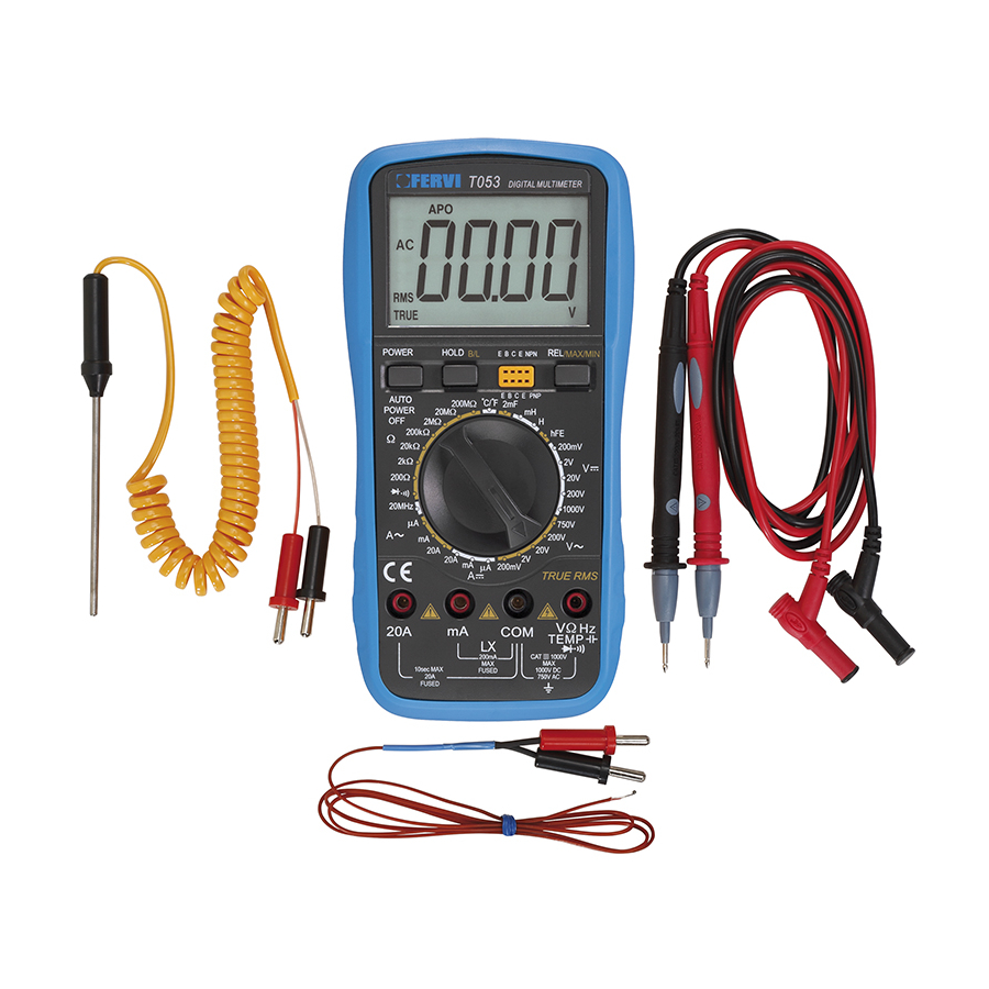
MEASURING INSTRUMENTS 1 INTRODUCTION This is a compact instrument, easy to handle, powered with a 9V battery, with a 65x42mm backlit LCD screen, designed for use by electrical and electronic engineers, electricians, students, hobbyists, who require an instrument that is: accurate, reliable and ready for use. Using the instrument, it is possible to measure: Voltage (AC/DC), Current (AC/DC), resistance, capacitance, inductance, temperature, frequency, diode and triode checks and continuity tests and also the instrument is equipped with a button for instant AC/DC... -
Page 5: Specifications
MEASURING INSTRUMENTS 2 SPECIFICATIONS 2.1 General Characteristics 65x42mm backlit LCD screen with maximum reading of 1999. Numbers measuring 27 mm Switch with 30 positions for selecting functions (FUNCTION) and ranges (RANGE) that allows easy and quick operations to be performed. ... -
Page 6: Technical Specifications
MEASURING INSTRUMENTS 2.2 Technical Specifications Atmospheric conditions: 23°C ± 5°C Relative humidity: MAX 75% 2.2.1 Voltage DCV Scale Accuracy Resolution 200mV 100μV ±(0.5%+3) 10mV 200V 100mV 1000V ±(1.0%+10) Input impedance: 10 M on all the scales Overload protection: 200mV scale: 250V DC or AC peak value, Other scales 1000V DC or AC peak value. -
Page 7: Alternating Current Aca
MEASURING INSTRUMENTS 2.2.4 Alternating current ACA Scale Accuracy Resolution 1μA ±(1.0%+15) 20mA 10μA 200mA ±(2.0%+5) 100μA ±(3.0%+10) 10mA Maximum measurable voltage drop: 200mV. Maximum input current 20A. Overload protection: 0.2A/250V;20A/250V. Frequency 40~200Hz. 2.2.5 Resistance Scale Accuracy Resolution 200 ±(0.8%+5) 0.1 2k... -
Page 8: Inductance (L)
MEASURING INSTRUMENTS 2.2.7 Inductance (L) Scale Accuracy Resolution 1μH 20mH 10μH 200mH ±(2.5%+30) 100μH 10mH Overload protection 36V DC or AC peak value. 2.2.8 Temperature (with probe supplied) Scale Accuracy Resolution ±(0.8%+5)<400°C (-20~1000) °C 1°C ±(1.5%+15)≥400°C Thermocouple type - K (yellow). 2.2.9 Frequency Scale Accuracy... -
Page 9: Using The Multimeter
MEASURING INSTRUMENTS 3 USING THE MULTIMETER 3.1 Preliminary notes If the battery is weak, the display shows the message “ ”, the battery should, therefore, be replaced. Check that the probes are in good condition. If they are damaged, replace them. ... -
Page 10: Measuring Dcv And Acv Voltage
MEASURING INSTRUMENTS 3.3 Measuring DCV and ACV voltage 1. Position the switch at the desired capacity. 2. Connect the red probe into the socket V/ and the black one into the COM socket. 3. Select, using the relative measuring scale wheel in relation to the value to be measured. -
Page 11: Measuring Resistors
MEASURING INSTRUMENTS 3.5 Measuring resistors 1. Connect the red probe into the socket V/ and the black one into the COM socket. 2. Select the desired capacity using the switch. 3. Connect the other end of the probes to the resistor to be measured and read the displayed value. -
Page 12: Measuring Frequency
MEASURING INSTRUMENTS 3.8 Measuring frequency 1. Position the function selector to "10MHz". 2. Connect the probes in series with the signal source to be checked and read the value. 3. NEVER apply more than 250V RMS in AC current. 3.9 Measuring temperature 1. -
Page 13: Transistor Tests
MEASURING INSTRUMENTS 3.11Transistor tests 1. Position the selector to “hFE” . 2. Make sure that the transistor is "NPN" or "PNP" type 3. Insert the transistor terminals into the appropriate socket on the instrument depending on whether it is NPN or PNP and make sure the E-B-C terminals are inserted properly. 4. -
Page 14: Replacing The Battery And The Fuses
MEASURING INSTRUMENTS 4 REPLACING THE BATTERY AND THE FUSES Opening the instrument Make sure that the instrument is disconnected and switched off before replacing the batteries and/or fuse. 1. Remove the multimeter from its protective casing. 2. Remove the screw securing the battery / fuse compartment cover, using a Phillips head screwdriver.
Need help?
Do you have a question about the T063 and is the answer not in the manual?
Questions and answers