
Summary of Contents for Rioned MULTI JET
- Page 1 USER’S MANUAL MULTI JET RIONED P.O. Box 5070 5004 EB Tilburg The Netherlands Telephone: +31 13 5479100 E-mail: info@rioned.com Internet: www.rioned.com...
- Page 2 RIONED. This restriction also holds for the corresponding drawings and diagrams. RIONED has the right to change parts at any time without any prior or direct warning to the client. Also, the contents of this manual can be changed without any prior warn- ing.
- Page 3 Foreword This user’s manual is a manual for the professional user. This user’s manual has the purpose to control the machine in a safety manner and must be kept with the machine. The photos and drawings help to understand the text easier. First the user’s manual gives an overview of the most important safety aspects.
- Page 4 01/18...
-
Page 5: Table Of Contents
Table of Contents Introduction ................7 1.1 Use ..................7 Security ..................9 2.1 Instruction indications in this manual........9 2.2 Descriptions security measures ..........9 2.3 Personnel protection outfit ............9 2.4 Warning ................9 2.5 Personnel qualification and education ........10 2.6 Danger that can occur if the security regulations aren’t observed 10 2.7 Working safely.............. - Page 6 7.6 Hose guide................40 7.7 Run dry protection ............... 40 7.8 Suction Ventury ..............41 7.9 Unwinding by hand of the hydraulic driven hose reel....41 7.10 Working lamp ..............42 7.11 Water circulation system with warm water ......43 7.12 Operating warm water system ..........
-
Page 7: Introduction
Introduction RIONED wishes to thank you for your purchase of the RIONED drain and sewer- clearing machine. We recommend that you read this manual thoroughly and see that the machine is handled and maintained in the proper manner. If your machine should give trouble and need servicing, when you want to order parts, or if you have any questions, contact your RIONED dealer. - Page 8 01/18...
-
Page 9: Security
Security Be responsible for other people when working with this machine. This manual contains instructions for fundamental conditions that must be fol- lowed by use and maintenance of this machine. That is why it is necessary that authorised and qualified personnel must read the user's manual and the user’s manual must always be available with the ma- chine. -
Page 10: Personnel Qualification And Education
Always use the break cable during transport. Never exceed the maximum speed (50 miles/h). 2.5 Personnel qualification and education Personnel that use, maintain and inspect the machine must have the right qual- ifications for this job. Responsibility and authorisation of the personnel and the supervision on the personnel must be embedded. -
Page 11: Making Changes And Fabricate Spare Parts
2.10 Making changes and fabricate spare parts Changes to the machine are only permitted if Rioned has given written author- isation. The use of original spare parts and accessories are for the safety nec- essary. Rioned is not responsible for injuries or damages if other spare parts are used. - Page 12 01/18...
-
Page 13: Technical Specifications
Technical Specifications. General Description (symbol) Unit Dimension : see chapter11.3 "Dimensions" page.: 58 Weight (dry) (m) : 1100 kg Total weight (m) : 1900 kg Quantity water tank : 2 x 400 l Fill medium : Water Maximum temperature medium : 50 °C Type tyre : 195R14... -
Page 14: Motor
Motor Description (symbol) Technical unit (SI unit) Type : Kubota V1505 Turbo Number of cylinder Bore x stroke (d x l) : 78 x 78,4 mm Power (P) : 32,7 kW at 3000 min DIN 70020 Fuel : Diesel Cooling : Water cooled Weight (m) : 114 kg... -
Page 15: Pump
Pump Description (symbol) Technical unit Type : Speck P45 Number of plungers Number of valves Maximum pressure (p) : See type plate on frame Maximum output : See type plate on frame Weight : 50 kg Maximum water temperature : 60 °C : GX 80W90 Quantity : 3.5 l... - Page 16 01/18...
-
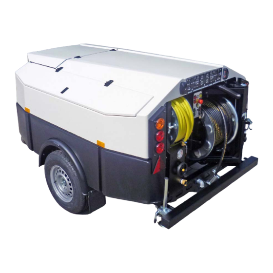
Page 17: Construction
CONSTRUCTION The high-pressure machine contains the following main parts: Tool box High-pressure hose on reel Supply hose on reel Water tank Machine cover Support (2x) Hose holder Hose guide Control box Supply pipe Hydraulic reel control Pressure gauge High-pressure (HP)-valve Level indicator water tanks Pressure regulator Pulsator system On/Off... - Page 18 Reel locking device Water filter Supply valve water filter Drain valve Hand wash Valve supply pipe Valve supply hose Motor-pump compartment 01/18...
- Page 19 Fuel tank with level indicator Hydraulic oil reservoir Trailer coupling Nose wheel Battery charger remote control Receiver Electric box Emergency stop 01/18...
- Page 20 Connection remote control 01/18...
-
Page 21: Control
Control If you control, maintain or inspect the machine, you must have the right qualifications for this job. If you do not have the necessarily knowledge, you may not use the machine. Further, you must convince yourself that you understand this manual thoroughly. - Page 22 Illustration 5.1.1 If a special DIN-eye is mounted on the tow bar (option) you use the eye instead of the coupling! 01/18...
-
Page 23: Check Before Departure
5.2 Check before departure Before you drive away with the vehicle, check the following: Are the supports (6) at its full height and locked? Is the high-pressure hose (2) been inserted into the hose holder (7) and secured with the securing pin. Is the reel control handle (11) in position “O”. -
Page 24: Before Starting
Mark the working area according the local regulations. 5.4 Before starting Check the oil level in the engine, oil reservoir (29) and high-pressure pump using the dipsticks. Add oil, if necessary. Check coolant level in reservoir. Check the level of the fuel in the fuel tank. Add fuel if necessary. Check Check whether the water filter (21) is clean. -
Page 25: Starting The Machine
This can be done in several ways: Via the supply hose (3). Unlock the supply reel and couple the end of the supply hose onto a water tap. Open the water tap and the supply valve. Via the supply pipe (10). Couple the end of a supply hose onto the supply pipe. - Page 26 Emergency stop (35) The machine is equipped with an emergency stop. By operating this stop the machine will stop immediately. Do not use the button for normal stopping. Only use is when dangerous situations occur. After use, turn the emergency stop in order to be able to start up again.
-
Page 27: Unclogging A Drain
By 5 channel radio remote control Put the key into the keyhole Choose “Hand” or “Radio ” remote control. Control lights Oil pressure and charging light- ens. If not, then “see chapter 8 "Maintenance" page.: 45“. Wait 5 seconds! Start the engine by pushing button on the control box. - Page 28 Press button (Throttle open). • Control by remote control (see chapter 7.5 "Radio remote control type Riomote" page.: 39): Press button 5 or (HP pump on). Press button 3 or (Throttle Open). The hose will now unwind and work its way into the drain. Check that the water drains away.
-
Page 29: Cleaning A Wall, Terrace Or Floor
Press button 4 or (Throttle close). Press button 6 or (HP pump off). Treat the high-pressure hose carefully: • Always clean it after use. • Ensure that no sharp objects are near the hose. • Ensure that no traffic crosses the hose. •... -
Page 30: Stop Working
Start spraying: Open the HP valve (13). Push button (Start spraying) on the control box or button 5 or on the radio remote control. Push button (Throttle open) on the control box or button 4 or on the radio remote control. Screw the high-pressure regulator wheel (15) upward on the high- pressure regulator until the required working pressure is reached. -
Page 31: Using The Device During Periods Of Frost
vent the system from flooding the surroundings. Turn the pressure regulator under the 150 bar (2175 psi). The pressure may never become over the 150 bar (2175 psi). Always treat the high-pressure hose well! 5.10 Using the device during periods of frost Your high-pressure device may freeze up during a period of frost. -
Page 32: Additional Preparations When Preparing For Use
Push button (Start spraying) on the control box and open the HP valve. Let the high-pressure pump fill the supply hose with antifreeze. Push button (Stop spraying) on the control box and close the HP-valve. Switch off the machine. Now the machine is ready for departure! 5.11 Additional preparations when preparing for use: Connect the high-pressure hose at the antifreeze tank. -
Page 33: Symbols
Symbols 6.1 Control box Start spraying (HP pump ON) Stop spraying (HP pump OFF) Throttle open (more water and more pressure) Throttle close (less water and less pressure) Signal lamp “Charging” (Burns if there is no charge to the bat- tery). -
Page 34: Pressure Gauge
Run dry protection (option) 12 volt accessories Back plate “Emergency stop” 6.2 Pressure gauge Maximum allowed pressure Danger zone Working area 6.3 Pressure regulator Less pressure More pressure 01/18... -
Page 35: Security Sticker
6.4 Security sticker 01/18... - Page 36 01/18...
-
Page 37: Options
Options 7.1 Hour counter This machine is equipped with an hour counter. The hour counter indicates the number of working hours that the machine has worked. 7.2 Anti-freeze with anti freeze tank Your high-pressure device may freeze up during a period of frost. A number of safety precautions must be taken. -
Page 38: Pulsator System
freeze flows out of the HP hose (watch the colour of the water). Connect the HP-hose (with special connection) to the supply hose. Open the supply valve (26). Close the HP valve, when anti freeze flows out of the supply hose (watch the colour of the water). -
Page 39: Hydraulic Reel Control
7.4 Hydraulic reel control By means of pushing the control lever upwards or downwards the high-pres- sure hose can be unrolled or rolled up. Due to the proportional functioning of this valve you can also control the speed of the reel. By putting the lever into the upper position you can unroll the hose manually. -
Page 40: Hose Guide
the battery must be changed with a new fully loaded battery. If the battery isn't changed the transmitter switches off in a short time. Reload empty batteries. Functions: Start the engine Stop the engine High-pressure pump on (start spraying) High-pressure pump off (stop spraying) Open gas of the engine Close gas of the engine Riopulse on/off... -
Page 41: Suction Ventury
Functioning: If the water level in the tank is too low, the run-dry protection activates. Cancelling: Fill the water tank. (Supply hose, Fill opening, Supply pipe...) 7.8 Suction Ventury Use: The suction ventury takes care that you can pump dirt and/or liquid out of res- ervoirs. -
Page 42: Working Lamp
The locking pin is released and the HP reel can turn freely without resistance. To get the HP reel in hydraulics you put the device in position “B”. The pin gets back in locking position and you can use the hydraulics again. 7.10 Working lamp By means of button you switch the working lamp on and off. -
Page 43: Water Circulation System With Warm Water
7.11 Water circulation system with warm water Purpose: To protect the machine against frost Construction: Because the engine runs, the water gets heated. The high-pressure circuit stays frost free. Control: • Start the engine (see chapter 5.5 "Starting the machine" page.: 25). •... -
Page 44: Operating Warm Water System
7.12 Operating warm water system Purpose: To obtain warm water for better cleaning. Preparation: Screw the correct jet nozzle at the end of the high pressure hose. Start the engine as previously described in this manual. Use: Photo old MultiJet! Put the handle A upwards to acti- vate the hot water system. -
Page 45: Maintenance
Maintenance Attention! Always stop the engine first and depressurize the system before serving or repairing the machine. To depressurize the system, you open the HP valve. If the spray lance gun is attached you must also pull the trigger. 8.1 Daily maintenance Oil level Check all oil levels before use. -
Page 46: Hydraulic System
Check the torque of the attachment bolts for the engine; tighten them, if necessary. For more information concerning the engine, you can find it in the book deliv- ered with this machine. Carriage: Lubricate all mechanical moving parts in the system. Check that all nuts and bolts have been correctly tightened. -
Page 47: Maintenance Wheel Bearings And Wheel Nuts
Stop the machine and repeat point 2 until 8. Maxi- Mini- 8.5 Maintenance wheel bearings and wheel nuts. After the first 50-100 km (30-60 miles) the wheel nuts must be checked on a good seat. If the seat is not good, pull the wheel nuts with a torque setting of 110 Nm. -
Page 48: Extensive Periodical Maintenance
8.7 Extensive periodical maintenance Have the high-pressure machine checked and maintained from time to time by the technical service of Rioned. In this way, long life and quality will be guar- anteed. 8.8 Maintenance scheme Interval Check oil levels Every time before use... -
Page 49: Troubleshooting
Troubleshooting Failure Reason Solution Engine does not start or stops Machine has run out of fuel Add fuel abruptly. Main or secondary fuse blown Replace the defect fuse and restart engine. If problem repeats, contact your dealer Battery voltage too low. Load or replace. - Page 50 Failure Reason Solution Hydraulic reel does not wind the Handle not on right position Put the handle into the right position hose Hydraulic tank almost empty Refill the tank. Check the system on leakage Attachment bolt for control lever of fasten the bolt and put the lever into hydraulic system loosened the correct position...
-
Page 51: Exploded Views And Part Lists
Exploded Views and part lists 01/18... -
Page 52: Exploded View Pump P52
10.1 Exploded view Pump P52 66-052-120-001 Antriebsgehäuse Crankcase 66-052-120-002 Ollauffüllstopfen kpl. Oil Filler Plug Assy 66-052-120-004 Getriebedeckel Crankcase Cover 66-052-120-005 O-Ring zu 4 O-Ring for 4 66-052-120-008 Meßstab kpl. Oil Dipstick Assy 66-052-120-009 O-Ring zu 8 O-Ring for 8 66-052-120-010 Zylinderschraube Cylinder Screw 66-052-120-011 Federring Spring Ring... -
Page 53: Exploded View Pump P45
10.2 Exploded view Pump P45 01/18... -
Page 54: Exploded View Pressure Regulator
10.3 Exploded view Pressure regulator Item No. Qty Order number Factory No. Description 1 67-262-101-001 01-0630 Casing 1 67-262-101-002 07-2788 Guide Plug 1 67-262-101-102 06-1131 Guide ring 1 67-262-101-003 06-0255 O-Ring 1 67-262-101-005 11-0477 Piston Rod 1 67-262-101-006 06-1129 O-Ring for 5 1 67-262-101-007 00-6113 Support Ring for 6... -
Page 55: Appendix
11.1 EC declaration Of Conformity For Machinery (Directive 2006/42/EC, Annex II, sub A) RIOR B.V. / RIONED Centaurusweg 45, Tilburg,The Netherlands, Herewith declares that: High pressure device RIONED MULTI JET, Machine number: • is in compliance with the Machinery Directive (2006/42/EC and 2007/46/EC);... -
Page 56: Sales Managers
EXPORT D.Maas Area Sales Manager Centaurusweg 45 5015 TC Tilburg Tel.: +31 13-547 91 00 Fax: +31 13-547 91 04 REPAIR THE NETHERLANDS Rioned Centaurusweg 45 5015 TC Tilburg Tel.: +31 13-547 91 50 Fax: +31 13-547 91 04 01/18... - Page 57 01/18...
-
Page 58: Dimensions
11.3 Dimensions REPORT UNDER CONSTRUCTION! 01/18... -
Page 59: Sound Level Report
11.4 Sound level report REPORT UNDER CONSTRUCTION! 01/18... - Page 60 01/18...
-
Page 61: Index
9 Gloves ....9 accessories ... 11 Responsability ..10 antifreeze ..... 32 responsible ....9 Attention ....29 Rioned ....2 ..11 injuries ....11 Caution ....29 safety break handle 21 Copyright ....2 maximum water temperature Sales managers ..
Need help?
Do you have a question about the MULTI JET and is the answer not in the manual?
Questions and answers