Table of Contents
Advertisement
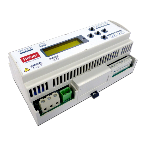
Product description
The 478 is for controlling DALI ballasts, LED drivers, emergency devices and load interface units (except for the 490 Blinds
Controller). The flexible control inputs route an input address/group command, as a broadcast, to its corresponding DALI
channel output. The 478 operates in one of two modes to support the connection of controls:
• Normal mode: No device addressing is required. Helvar compatible presence sensors can be connected in addition to
DALI compatible control gear. The sensors provide local occupancy control for the DALI channels' output to which they
are connected. Do not connect controls other than those listed (see 'Sensors' on page 7) to the DALI outputs (DALI
channels 1–8). This mode provides support for emergency devices only when using the DALI control input.
• Toolbox mode (Default): This allows a DALI output channel to act as a power supply, so that any DALI compatible
control gear or Helvar DIGIDIM controls can be connected. No automatic addressing takes place, so all the devices
connected on the DALI output channel must be programmed using Helvar's Toolbox software. Output levels received
on the control inputs are broadcast on the corresponding output channel to provide local override. The 'Toolbox mode'
option is available from the control panel. For more information, see 'Set Toolbox mode' on page 10.
LCD
DALI channels
The 478 can control up to 8 DALI channels, each of up to 64 devices (limited by current consumption).
Control inputs
The 478 can be controlled using DALI, SDIM or DMX, and an override input.
NOTE: DALI AND SDIM/DMX MUST NOT BE CONNECTED SIMULTANEOUSLY.
LCD display and control panel buttons
The front of the module has an LCD and five buttons to set basic configuration parameters and provide basic control of
channel levels.
Note: The content of this manual refers to the operation of a 478 with firmware version 2.4 or later.
Helvar | Data is subject to change without notice.
Installation and User Guide
8-Subnet DALI Controller (478)
SDIM/DMX
Override
control
input
TERM
B
SC
0V
A
0V OVR
S-DIM
S-DIM
S-DIM
OVERRIDE
478 DALI Controller
(85 to 264)VAC
DALI SYSTEM
OVERRIDE
L
N
N
E
DA+ DA-
Mains supply
DALI control
DALI channels 5–8
D5
D-
D6
D-
D7
D-
D8
D-
Ch5
Ch6
Ch7
Ch8
DALI CHANNELS
OK
DALI CHANNELS
Ch1
Ch2
Ch3
Ch4
D1
D-
D2
D-
D3
D-
D4
D-
DALI channels 1–4
Status LED
Control
Panel
Buttons
www.helvar.com
i
Advertisement
Table of Contents

Related Manuals for HELVAR Digidim DALI 478


Summary of Contents for HELVAR Digidim DALI 478
- Page 1 The 478 operates in one of two modes to support the connection of controls: • Normal mode: No device addressing is required. Helvar compatible presence sensors can be connected in addition to DALI compatible control gear. The sensors provide local occupancy control for the DALI channels’ output to which they are connected.
-
Page 2: Table Of Contents
Contents Section Page Product description Mounting, environmental and clearance requirements Installation Connections Configuration Adjust channel levels using the buttons Module Menu Options Menu Options Details Status messages Technical Data Helvar | Data is subject to change without notice. www.helvar.com... -
Page 3: Mounting, Environmental And Clearance Requirements
(Earth/Ground): must be 0 V: (Data reference) connected D1;D2;D3;D4;D5;D6;D7;D8 (Screen: not data reference) DA– D– DALI control Term: (Link to B for termination) Note: Max. 64 devices per channel DA+ & DA– Helvar 478 8 Channel DALI Controller: Installation and User Guide... - Page 4 = SDIM or DMX Data Cable (from previous device) iv = Link for Termination (if unit is at end of SDIM/ DMX cable line) Note: Keep unscreened wire lengths to a minimum. Helvar 478 8-Subnet DALI Controller: Installation and User Guide...
- Page 5 Configure the 478 using Designer or Toolbox software Designer If the 478 is connected to a router-based system (Helvar 905, 910 or 920 router), connect a PC to the router, and configure the 478 using Designer. Toolbox You can configure the 478 using a Windows PC (running Helvar’s Toolbox software, v.
-
Page 6: Configuration
Note that the 478 is intended for controlling DALI ballasts, drivers and load interface units (except for the 490 Blinds Controller). Do not connect controls to the DALI outputs (DALI channels 1–8), other than Helvar compatible sensors (see ‘Sensors’ on page 7), unless you selected Toolbox mode. - Page 7 Use the UP and DOWN buttons to adjust the level of all the channels as required. c. Return to the main display screen To return to the main display screen, press the OK button. Helvar 478 8 Channel DALI Controller: Installation and User Guide...
-
Page 8: Module Menu Options
Reset all settings to factory defaults. Use password Apply password lock to settings (except to ‘Unit details’ and ‘Enter password’ items). Enter password Allow changes to settings when password lock is applied (see ‘Use password’) Helvar 478 8-Subnet DALI Controller: Installation and User Guide... -
Page 9: Menu Options Details
‘Emergencies’ screen. Subsequently, you can turn it on again with the UP button. Sensors The following Helvar presence sensors can be connected to this unit as long as their firmware versions are 6.37 or later: 311 Ceiling PIR Detector, 312 Multisensor, 313 Low-Profile Microwave Detector, 314 Tilting Microwave Detector, 315 iDim Sense, 317 High-Bay Presence/Absence Detector, and 318 Wall-Mounted PIR Presence/Absence Detector. - Page 10 ‘Normal’ Recall scene Recall a scene previously stored (temporarily if connected to a Helvar router system). Scenes are sets of lighting levels and can make use of any combination of channels. This option is always available, even when password protection is applied to other options.
- Page 11 0 % = OFF, and 1 % or more = ‘Loads at 100 %’. Options: Channel: 1–8; Minimum level: 0.1 %; 1 % – 100 %; (Default: 0.1 %) Helvar 478 8 Channel DALI Controller: Installation and User Guide...
- Page 12 When this mode is enabled, each DALI output channel only acts as a power supply. Any DALI compatible control gear or Helvar DIGIDIM controls can be connected to the unit. However, all the devices on the outputs must be configured separately with Helvar’s Toolbox software, as no automatic addressing takes place in this mode.
-
Page 13: Status Messages
Fault with one or more DALI channels: see messages under ‘DALI channel selected’ on page 12. No emergency ballast found No emergency ballast could be detected on the selected channel. Helvar 478 8 Channel DALI Controller: Installation and User Guide... - Page 14 Note: The 478 also reports DALI lamp failure on the DALI control input. If no devices are connected to an output, it will report back DALI lamp failure. This makes it easy to detect disconnected outputs. Helvar 478 8-Subnet DALI Controller: Installation and User Guide...
-
Page 15: Technical Data
Helvar Ltd Relative humidity: Max. 90 %, noncondensing Hawley Mill Hawley Road Storage DARTFORD temperature: –10 °C to +70 °C DA2 7SY UNITED KINGDOM www.helvar.com Helvar 478 8 Channel DALI Controller: Installation and User Guide Doc. 7860319, issue 5, 2019-01-28...
Need help?
Do you have a question about the Digidim DALI 478 and is the answer not in the manual?
Questions and answers