Table of Contents
Advertisement
Quick Links
Part
Part
#
Name
1
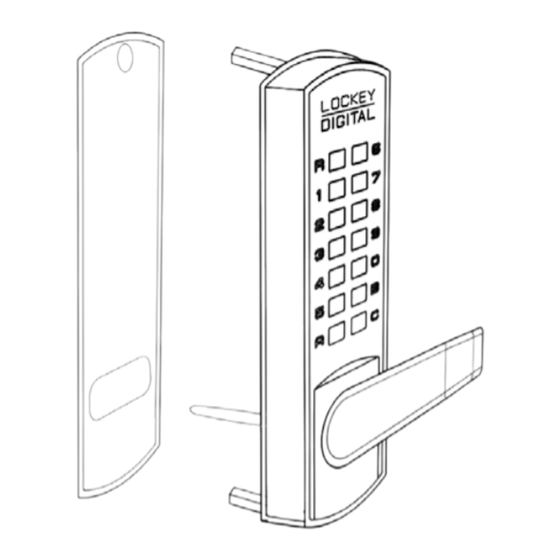
Outside Body
2
Inside Body
3
Lever/Knob
4
Rubber Trim Plate
5
Strike Plate
6
Mortised Striker
7
Spindle
8
Allen Wrench
9
Machine Screw M4 x 30mm
10
Machine Screw M4 x 40mm
11
Machine Screw M4 x 50mm
12
Wood Screw M4 x 16mm
13
Extra Code Tumblers (Red)
14
Extra Non-Code Tumblers (Blue)
15
Adjustable Latch (2
16
Support Pin
17
Tweezers
18
Hex Bolts
Important information about your lock:
1. When the door is closed, the system locks automatically.
2. From the inside, unlock using the knob or lever. For DC locks, unlock using the User Code, followed by
the knob or lever.
3. From the outside, unlock by pressing 'C' (CLEAR), followed by your User Code.
4. Your lock is equipped with a PASSAGE FUNCTION, allowing you to leave the door unlocked.
To enable the passage function:
Press 'C' (CLEAR), then 'R' (PASSAGE), then enter User Code.
To disable the passage function:
Press 'R' (PASSAGE), followed by 'C' (CLEAR).
To disable the passage function PERMANENTLY:
Remove the 'R' (PASSAGE) tumbler, leaving that slot empty.
IMPORTANT: Always press and hold the 'C' Button when removing and inserting Tumblers.
Refer to 'How to Change Code' instructions on reverse side.
Installing your lock:
Step 1: Before installing, if you would like to change the user code,
follow instructions on reverse side.
Step 2: Prepare door for installation with template.
Place the supplied template on door and fold along the door edge.
Mark holes for 2 3/8" or 2 3/4" backset. Drill holes as instructed.
Step 3: Identify door handing, attach support pin (#16), attach hex bolts (#18)
Right Hand Doors- From exterior of door, hinges are on the right side.
If you have a Right Hand Door, screw support pin (#16) into position A.
Left Hand Doors- From exterior of door, hinges are on the left side.
If you have a Left Hand Door, screw support pin (#16) into position B.
Next, screw hex bolts (#18) into the top and bottom as shown.
Installation Instructions
#
Included
# Included
1
1
2/2
2
1
1
1
1
2
2
2
4
1
2
3/8
" -2
3/4
")
1
1
1
2
3830/3835
DC Lock
9/10/11
1
2
1
2/2
2
1
9/10/11
1
1
1
2
2
15
2
12
4
2
3
12
1
1
1
2
3830
Knob
4
7
6
5
8
12
12
Right Hand Doors
Support Pin
Position A
3835
Lever
18
4
1
7
3
16
17
13
14
R Tumbler
Left Hand Doors
Support Pin
pg 1
Position B
Advertisement
Table of Contents

Related Manuals for LOCKEY USA 3835


Summary of Contents for LOCKEY USA 3835
- Page 1 3830 3835 3830/3835 Knob Lever Installation Instructions Part Part DC Lock Name Included # Included 9/10/11 Outside Body Inside Body Lever/Knob Rubber Trim Plate Strike Plate 9/10/11 Mortised Striker Spindle Allen Wrench Machine Screw M4 x 30mm Machine Screw M4 x 40mm...
- Page 2 Using the allen wrench, install handles (#3) to the inside and outside lock bodies. Secure with set screws. ** IMPORTANT** 3835 Lever handles should point toward door hinges. Note: 3835 has a slip clutch to prevent damage during an attempted forced entry. If you find the lever handle pointing down, pull lever back to desired position.
Need help?
Do you have a question about the 3835 and is the answer not in the manual?
Questions and answers