Table of Contents
Advertisement
Advertisement
Table of Contents

Related Manuals for OrthAlign HipAlign

Summary of Contents for OrthAlign HipAlign
- Page 1 Surgical Technique Manual HipAlign ® Total Hip Arthroplasty Posterior Approach...
-
Page 2: Table Of Contents
Table of Contents General Operation …………………………………………………………………….. 3 Tips and Warnings ……………………………………………………………………. 3 Pre-Op …………………………………………………………………………………. 4 Patient Positioning …………………………………………………………….. 4 Opening and Powering On the Navigation Unit ……………………………... 4 Back-Table Set Up ……………………………………………………………………. 5 Calibration Steps ………………………………………………………………. 6 Prepare Instruments …………………………………………………………... 7 Attach Laser ……………………………………………………………………. -
Page 3: General Operation
NAVIGATION UNIT / REFERENCE SENSOR: Risk of communication errors increases if multiple OrthAlign Plus® systems are used in close proximity. If navigation unit is dropped on floor, it must be discarded. If reference sensor is dropped on floor, it must be returned to manufacturer for verification of function and calibration. -
Page 4: Pre-Op
Pre-Op Patient Positioning VIEW FROM SIDE VIEW FROM ABOVE Parallel to table edge Table Table edge Patient must be placed in the lateral decubitus position. When positioning patient prior to surgery, take care to align the anterior pelvic landmarks (both ASIS’s and pubic tubercle) in a vertical plane parallel to the long edge of the operating table. -
Page 5: Back-Table Set Up
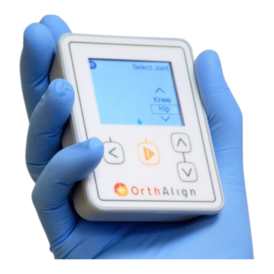
Back-Table Set Up Select Joint Select Joint Use center button to select Hip. Knee Select Approach Select Approach Use center button to select approach. Posterior Anterior Install Sensor Battery STEP 1: Install Sensor Battery Insert battery into reference sensor and close cover. TIP: Reference sensor LED will slowly flash yellow to indicate battery has been inserted correctly. -
Page 6: Calibration Steps
Calibration Steps TIPS FOR CALIBRATION STEPS: Navigation unit must be maintained in steady position, or calibration will not be accepted. A red hand will flash on screen if unit is not steady. Level circle must be green, but ball does not need to be in exact center of circle. ... -
Page 7: Prepare Instruments
Prepare Instruments Remove required instruments from tray, and prepare them for use. Select appropriate shell adapter. See “Shell Adapter Options” table below. Note: The Probe Calibration Jig is not required for this procedure. Hex Driver - 3.5MM, Teardrop 403105 Probe Calibration Jig –... -
Page 8: Attach Laser
Attach Laser to Pelvic Base Attach Laser Step 9: Attach Laser Close shutter on the laser module. Insert battery Screw onto Insert battery and close cover. bracket Attach laser to the posterior side of the bracket at a selected angle. The laser can be angled downward to project more proximal or angled straight to project more distally. -
Page 9: Securing Base To Bone
Secure Base on Bone Securing Base Pelvic Base Securing Pelvic Base Placement of the fixation pins in the iliac crest should be vertical to optimize orientation of the instrumentation. Make a second stab incision, and insert For the first pin, make a stab incision Slide the Pelvic Base over both pins to the second fixation pin in the iliac crest over the ipsilateral iliac crest, directly... -
Page 10: Attaching Sensors And Registration Of Landmarks
Attaching Sensors and Registration of Landmarks Attach Sensors Attaching Sensors Attach probe to jig Attach jig to Attach pelvic bracket and probe to pelvic base. pelvic base reference TIP: Attach sensor to TIP: Attach pelvic bracket, with TIP: Attach probe assembly to pelvic probe by aligning arrows on sensor navigation unit attached, to coupler base by aligning arrows on probe... -
Page 11: Aligning Jig
Aligning Jig Align Jig Aim Laser at Distal Thigh Place the leg on the operative side in a neutral abduction, flexion and rotation using a roll if necessary. Place the thigh plate on the lateral distal thigh and secure using Coban™... -
Page 12: Registrations
Registrations Register Home Register Home Place probe tip in hole of pelvic base Place tip of probe into hole of the pelvic base and press center button. Keep pelvic base locked throughout procedure Register Table Register Table Verify sagittal plane of pelvis is level and Position operating table horizontally. -
Page 13: Options Menu
Options Menu Set/check the angle of the cup by navigating impactor. Re-register Homepoint. The change in position Title changes to “Check Cup NOTE: Selection Option of probe tip between original and current Angle” after cup angle has been position is displayed. Set Cup Angle “Set”. -
Page 14: Set / Check Cup Angle
Once reference sensor is attached to impactor, navigation unit displays abduction and anteversion angles based on the Table reference frame. The OrthAlign Plus® System does not navigate or control shell impaction depth or insertion point. Please refer to implant manufacturer’s technique guide for guidance. WARNING: ... -
Page 15: Check Leg Length
Check Leg Length Step F5: Attach Sensors Attach probe with reference sensor to jig Step F5A: Position Femur Position the magnetic vertical target on the distal thigh Open shutter on laser Re-align leg so that the laser projection aligns with the marking on the vertical target. NOTE: Ensure laser lens is clear. -
Page 16: Repeat Registrations
Repeat Registrations Warning Repeating registrations will result in a loss of all previous registrations. All previous registrations will be lost Cancel Proceed Warning: Has Femur Tack or Pelvic Base moved? Determine if pelvic base has moved, and select ‘Yes’ or ‘No’ to continue repeating registrations End Procedure Warning... -
Page 17: Compilation Of Instruments With Part Numbers
Instruments with Part Numbers Part Number Part Description Quantity 403105 Hex Driver - 3.5MM, Teardrop 403258 Probe Calibration Jig - Tripod 403370 Laser Module 403305 Registration Probe 403306 Pelvic Base, Anterior 403307 Pelvic Bracket Assembly, Short 403338 Straight Cup Impactor 405001 Reference Sensor 5 Hip (RS5H) or 403087-06... -
Page 18: Instrument Tray Configuration For Sterilization
Instrument Tray Configuration for Sterilization Position Instruments in Instrument Tray as shown below for sterilization. Refer to the Instructions for Use for details on cleaning and sterilization parameters. Vertical Laser Target Shell Adapters Laser Module Thigh Plate Pelvic Base... -
Page 19: Troubleshooting
Battery may need to be replaced. Press center button to repeat detected for registration. registration. Check that no concurrent OrthAlign or KneeAlign cases are being conducted. There is a risk of communication interference between electronic units if multiple cases are conducted in close proximity. - Page 20 If ‘Yes’ is selected, leg length and replaced. Please recover faulty unit and fault reoccurs after re-starting, power unit offset measurements will be disabled. return to manufacturer for analysis. off and replace it. Contact OrthAlign and return unit for further analysis.
- Page 21 About OrthAlign, Inc. OrthAlign is committed to providing surgeons with user-friendly, cost-effective, surgical navigation products for precise alignment. For more information about the OrthAlign Plus® System, please contact us at 949.715.2424 or info@orthalign.com 120 Columbia, Suite 500 Aliso Viejo, CA 92656 Phone: 949.715.2424...
Need help?
Do you have a question about the HipAlign and is the answer not in the manual?
Questions and answers