Table of Contents

Related Manuals for PNI SafeHouse HS550


Summary of Contents for PNI SafeHouse HS550
- Page 1 Sistem de alarma fara fir PNI SafeHouse HS550 Wifi GSM 3G PNI SafeHouse HS550 WIRELESS 3G alarm system Manual de utilizare / User manual Manual de utilizare..... 2 User manual ....... 22...
-
Page 2: Features And General Information
WARNING Please read this user manual carefully before using the product. To set up and use the alarm system correctly, we recommend that you read this manual thoroughly and carefully. Configuring and installing this system requires basic technical knowledge, IT and PC, in order to understand and interpret the technical terms and procedures correctly. -
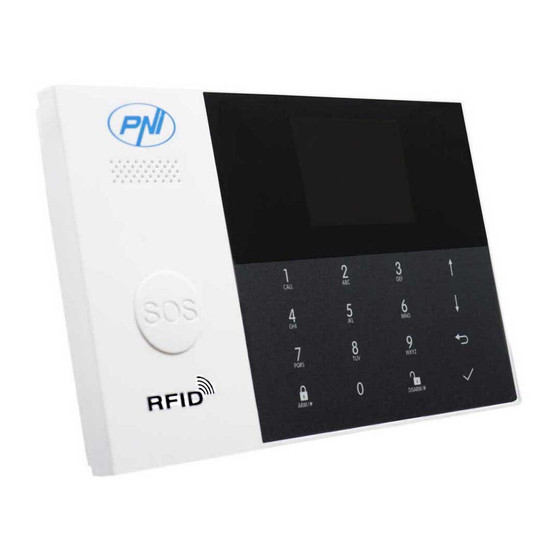
Page 3: System Overview
2. SYSTEM OVERVIEW 2.1 Control panel description Index Item Description Display Window 2.4 TFT Display screen. Displays system status icons and information, time, zone(s) alarm information, user menus. Speaker Alarms and confirmation sounds. Panic Key Press to generate a Panic Alarm in case of fire or personal emergency. - Page 4 About the Backlight Indicators of Panic Key What you see What it it means Blinking alternately System is in Alarm Pulse System is Armed Steady System is Disarmed 2.2 Wiring overview Index Description Power Supply plug Backup Battery Switch SIM card socket EOLR Hardwired Zones Connections, refer to section 2.3 and the Hardwired Zones Connections diagram Tamper switch...
-
Page 5: Home Screen Description
EOLR EOLR EOLR the Hardwired Zones Connections Diagram EOLR(End of Line Resistor): If the EOLR is not at the end of the loop, the zone will not be properly supervised, and the system may not respond to an open circuit on the zone. 2.4 Home Screen 3 4 5 2018-01-02... - Page 6 WIFI Indicates that the system is connected to a WIFI WiFi source and the signal strength. Wi-Fi Status Indicates that the system is connected to the server if dot is displayed. SMS Sending Calling Keypad Locked Top Status AC Powered Power Status 0~3 bars Displayed when the system has lost AC...
- Page 7 Sniffer Mode “Synchronizing” You must active the wireless transmitter before the Countdown Bar sniffer delay expires. Alarming “Alarm” is displayed upper the red bar, and the Zone “Alarm” is displayed in a red status bar along the red bar. An alarm (bell) icon along with “Alarm” is displayed alternately with the Zone that has caused the alarm.
- Page 8 Enable/Disable operation Enable chime Keypad Tone Enable/Disable entry and Enable exit chime Delay Tick Switch Enable/Disable Exit Alarm Enable Warning Door/Window Open Warning Change System Code 4 digits 6666 System Change User Code Password 4 digits 1234 User English Deutsch Settings РУССКИЙ...
- Page 9 Used to set the second Phone Number, Enable/Disable Dialling and Enable/ Null 2nd Phone Disable SMS Used to set the third Phone Number, Enable/Disable Dialling and Enable/ Null 3rd Phone Disable SMS Used to set the fouth Phone Number, Phone Enable/Disable Dialling and Enable/ Null 4th Phone...
- Page 10 Pairing with the alarm syncing wireless Alarm Socket switch Pairing with the wireless switch Socket WiFi configuration (Requires the mobile Airlink APP). Unbind Unbind the Panel link from the server Wi-Fi Used to display the MAC and IP MAC/IP addresses of the WiFi module Message Recording and Playback Record Used to listen to the recorded message...
- Page 11 Used to display the firmware and MAC address of the WiFi module, the firmware and IMEI of the GSM module and Serial Number of panel Version Description 1. Arm Beep: When enabled, the system will announce the system status when armed or disarmed.
-
Page 12: The First Usage
3. THE FIRST USAGE 3.1 Set up With the built-in WiFi Communications module, if your system is equipped to report alarms and Remote Access via Mobile APP over the internet, your router must remain powered-on at all times, and a WiFi internet connection is required. With the built-in GSM/3G Communications module, if your system is equipped to report alarms and Remote control via SMS or Voice Dialling, to ensure the SIM card is installed (refer to the diagram below ) and the panel must be connected to the GSM/3G... -
Page 13: Wireless Keys
3.3 Wireless Keys Pairing a New Wireless Key - Select ”Main Menu->Parts->Remote->Add”. - “Synchronizing” is displayed, the system goes into the sniffer mode and count down the pairing time remaining . - Press one button of wireless key to send a transmission signal to the panel. - As the serial number of wireless key is added to panel, “Leaning OK”will be displayed. -
Page 14: Pairing With Wireless Siren
Edit/Delete - Select “Main Menu->Parts->Detector->Edit”. - Use the buttons to scroll to the serial number be edited. - To edit the Name/Mode/Number of displayed zone, press - To delete the selected serial number, press Delete All - Select “Main Menu->Parts->Detector->Delete All”. - A total number of serial numbers learned is displayed. -
Page 15: Arm/Disarm Automatically
- Operating the Wireless Switch to go into the Sniffer mode( refer to user guide of wireless switch ) . - Press the “on” button and the “off”button in turn , The panel displays ” Learn Signal Sent” and sends a transmission signal twice to the Wireless Switch. - The Wireless Switch gives a successful indication. -
Page 16: Remote Sms
- Press to save your new settings. 4. MOBILE APP PNI SAFEHOUSE HS550 Scan the QR codes via a smart phone to download the app. PNI SafeHouse HS550 app will guide you to connect the panel to the WiFi network and the internet. 5. REMOTE SMS 5.1 How to set the parameters via SMS... -
Page 17: The Alarm Sms Notification Prefix
Note: The examples uses the default system password 6666. 1. The Phone Number setting format of remote text message: 07xxxxxxxx,A,B In this string: “07xxxxxxxx” is the phone number( up to 18 digits ), - “A” used to Enable(1) or Disable(0) the Alarm Voice Dialling and - “B”... - Page 18 5.3 How to set the customized Zone Name 5.4.1 Query the system settings Format is *6666*62*, and the panel echoes as follow. SYSTEM set: Serial Number of the panel LANGUAGE: Language ENGINEER PASSWORD: System Password USER PASSWORD: User Password GSM CSQ: GSM(0-99 Level) RSSI WIFI RSSI: Wifi RSSI...
-
Page 19: Securing The Premises
7. SECURING THE PREMISES 7.1 Arming the System To arm the system, you can operate as below: By Wireless Key: Press key. By Panel: Press button when home screen is displayed. By RFID tag: Put the RFID tag close to the RFID area when system is disarmed. By APP: Press the Arm icon, then select the Exit Delay. -
Page 20: Sos Function
By remote SMS: Send a message 1234#2 (“1234”is User Password) to the panel, then an acknowledgement SMS will be returned if armed. The system will announce “System Disarmed”. Home Screen will displays the “Disarmed”icon. If the “Arm SMS” is enabled, you will receive a SMS notification. 7.4 SOS Function To manually active panic function, you can operate as below: By Wireless Key: Press... -
Page 21: Specifications
9. SPECIFICATIONS - Primary Power: Plug-in Power Supply, micro USB 110/220VAC to 5VDC, 1A output - Backup battery: 3.7V/500mAh Rechargeable Lithium Polymer Battery - Consumption: <150mA@normal - Siren Output: <300mA - Radio Frequency: /433 - RF code: eV1527 - GSM: 850/900/1800/1900MHz - Wi-Fi: IEEE802.11b/g/n - Operation Temperature: 0~55 - Dimensiuni unitate: 180x115x22 mm... - Page 22 Declaración UE de conformidad simplificada SC ONLINESHOP SRL declara que el Sistema de alarma PNI SafeHouse HS550 cumple con la Directiva EMC 2014/30/EU y la Directiva RED 2014/53/EU. El texto completo de la declaración de conformidad de la UE está...
Need help?
Do you have a question about the SafeHouse HS550 and is the answer not in the manual?
Questions and answers