Table of Contents
Advertisement
Advertisement
Table of Contents

Related Manuals for Simplex Saturn Series

Summary of Contents for Simplex Saturn Series
- Page 1 SATURN 1400KW-3200KW STATIONARY LOAD BANK...
- Page 2 Last Revision Date: March 15, 2016 For the most up-to-date information for this product and others, please contact Simplex, Inc. at (800) 637-8603 or visit us on the web at http://www.simplexdirect.com.
-
Page 3: Table Of Contents
Table of Contents Warnings and Cautions ............1 Safety information symbols Cautions Description and Specification ..........4 Overview of Use Control System Cooling System Load System Safety Unpacking ................6 Included Components Primary Inspection Installation ................7 Load Bank Placement Installation Procedure Remote HMI installation Load Dump installation... - Page 4 Maintenance/Troubleshooting ..........21 General maintenance Each Operation Every 6 Months Troubleshooting Alarms and Warnings ............23 Alarms Warnings AppeNDIx A — pARTS LISTINGS ............25 AppeNDIx B — MODBUS CONTROLS ...........41 Modbus Control Directions AppeNDIx C — pRODUCT WARRANTY ..........45...
- Page 5 Table of Figures Current draw at specific resolutions (in kilowatts) .......5 Air Flow ........................7 Ground Bus ......................8 Main Load Bus ....................8 Conduit Opening ....................8 HMI TBH........................9 Serial Adapter ....................9 TB-DC ........................9 Load Dump Jumper ..................10 Current Transformers ................... 11 CT Orientation ....................
- Page 6 Option B - Communication (TCP/IP Data Logging) ......27 PLC Component list ..................28 Control Relays ....................30 Terminal Blocks ....................32 Option 010 - Space Heaters ............... 34 Center Subpanel .................... 36 Phase A Detail ....................37 Phase B Detail ....................38 Phase C Detail ....................
-
Page 7: Warnings And Cautions
1 WARNINGS AND CAUTIONS The following images indicate important safety information: afety information This General warning symbol points out important SymbolS information that, if not followed, could endanger personal safety and/or property. This Explosion warning symbol points out potential explosion hazards. This Fire warning symbol points out potential fire hazards. - Page 8 to large cubic airflow requirements, exhaust temperature, and velocity. Do not point exhaust at any nearby surface or object that may be adversely affected by high temperature. This includes but is not limited to painted surfaces, tar paper and asphalt roofs, water sprinkler heads, fire alarms, and volatile material.
- Page 9 equipment only while standing on such insulative mats. • The National Electrical Code (NEC), Article 250 requires the frame to be connected to an approved earth ground and/or grounding rods. This grounding will help prevent dangerous electrical shock that might be caused by a ground fault condition or by static electricity.
-
Page 10: Description And Specification
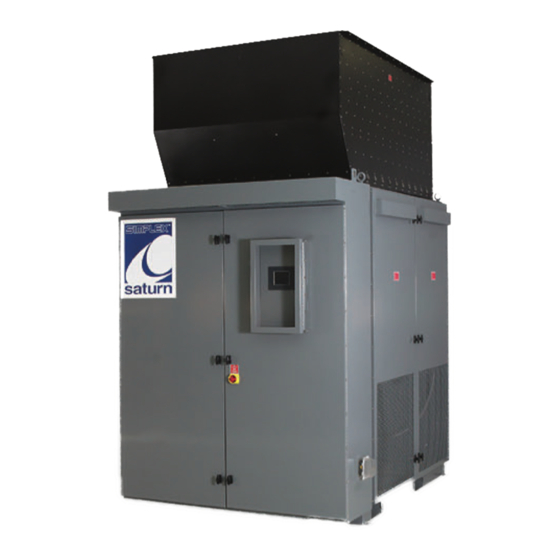
2 DeSCRIpTION AND SpeCIFICATION Simplex Saturn load banks are precision test instruments verview of designed to apply a selectable load to a power source and measure the source’s response. They are used for routine maintenance exercise to ensure the long-term reliability and readiness of the standby generator. - Page 11 1400 1500 1600 1700 416V 1943A 2082A 2221A 2359A 480V 1684A 1804A 1925A 2045A 600V 1347A 1443A 1540A 1636A 1800 1900 2000 2100 2200 416V 2498A 2637A 2776A 2915A 3053A 480V 2165A 2285A 2406A 2526A 2646A 600V 1732A 1828A 1925A 2021A 2117A 2300...
-
Page 12: Unpacking
3 UNpACKING The following items are included with your load bank. If any nCluded of the following are not included, please contact Simplex Direct omponentS at 800-637-8603. 1. Load bank 2. Controller (remote or local) 3. Manual 4. Drawing package Optional equipment 1. -
Page 13: Installation
4 INSTALLATION Figure 1 Air Flow Normally equipped, Saturn load banks laCement intended outdoor installation. A forced air system, which discharges out of the top of the unit, cools the load elements Figure 1 Air Flow.) (See Load banks require large quantities of air circulation, Improperly so it is essential to install the... -
Page 14: Installation Procedure
Figure 2 Ground Bus 1. To bring in the source’s nStallation power cables, pull holes roCedure in the Conduit Opening, located in the bottom of the load bank’s control panel enclosure (see Saturn load Figure Conduit banks feature Opening). a power 2. -
Page 15: Remote Hmi Installation
Figure 5 HMI TBH If your HMI is installed emote directly on the load bank, inStallation skip to the next section. 1. Mount the HMI where desired. 2. Connect the HMI to the Load Bank by swinging the HMI’s screen out to expose the TB-H terminal Figure 6 HMI block (see... -
Page 16: Load Dump Installation
Load Dump Figure 8 feature is desired, remove Load Dump Jumper inStallation factory-installed jumper at TB-R 1–2 and connect customer-supplied Load Dump contacts to Figure 9 TB-R 1–2 (See Load Dump Jumper). To dump the load, open the customer-supplied contact. To enable load, close the customer-supplied contact. -
Page 17: Current Transformer Installation
Figure 9 If your load bank is urrent Current Transformers equipped with Metering, ranSformer Automatic Mode inStallation Regenerative Mode options, you will have to install current transformers your power cable. • For metering mode, install current transformers on the load bank leg of your power “Figure 13 system (see... -
Page 18: Current Transformer Placement For Metering
Figure 12 Current Transformer placement for Metering Figure 13 Current Transformer placement for Auto/Regen. Mode The first current transformer must be installed on Phase A, and the second must be installed on Phase C. 12 — Installation... -
Page 19: Modbus Installation
Figure 14 TB-COM modbuS The Saturn load bank supports Modbus inStallation protocol, implemented either as RS485 or TCP/ IP (which is an optional upgrade). To implement Modbus control monitoring, connect the load bank to your facility’s systems as follows: For RS485: Figure 15 Modbus Serial 1. -
Page 20: Heater Installation
Figure 16 TB-SH Saturn load banks are eater equipped with space heaters inStallation for cold weather operation and to prevent condensation, which damage unit. The heaters require a dedicated power source independent control power at all times to prevent startup failure due to cold environments. -
Page 21: Bms/Bas Installation
bmS/baS Figure 17 TBR The Polaris provides a set of Remote Signal Dry nStallation Contacts, which allow you to integrate the load bank into your Building Management System (BMS) or Building Automation System (BAS) The dry contacts provide an alarm message, letting you know if the load bank has failed. -
Page 22: Setup
1. General Settings 2. Automatic Mode Settings 3. Test Mode (Intended only for Simplex engineers) 4. Factory Setup (Intended only for Simplex engineers) You can access General Settings and Automatic Mode Settings by pressing their respective buttons. -
Page 23: Operating Instructions
6 OpeRATING INSTRUCTIONS Figure 20 Fan/Control 1. Start the generator or operation Power Disconnect Switch source being tested. CHeCkS 2. Ensure the load bank’s Fan/Control Power Saturn load Disconnect Switch, banks feature located on the unit’s door, a power is in the on position (see outlet in the Figure 21 Fan/Control control panel... -
Page 24: Testing Operation
If any of three voltage or current values are significantly different from the other two, check the load bank for a blown fuse. If no blown fuse is found, contact Simplex service at 800-637-8603, ext. 4. Pressing “Alarm History” on this screen will bring up a list of Figure 27.) -
Page 25: Automatic Mode
7 AUTOMATIC MODe Figure 26 Setup Screen The Saturn load bank can be equipped with an optional automatic mode, which will extend your generator’s life by protecting it against wet- stacking and reverse current. Automatic Mode adds Figure 27 Automatic verview load when the load bank Mode Setup... -
Page 26: Setting Up Automatic Mode
Figure 29 Automatic the preset maximum value, Mode Running it begins removing load until the draw is back within the designated range. Before activate etting Automatic Mode, you must utomatiC configure the load bank to interact with your generator. The values Enter the Automatic mode you will need setup screen by pressing the “F4 Setup”... - Page 27 8 MAINTeNANCe/TROUBLeSHOOTING The load bank has been designed to require minimum eneral maintenance. All components have been chosen for a long, maintenanCe reliable life. Two basic intervals of maintenance are required: each operation and every 6 months. • Check the air intake screens and louvers, fan and cooling chamber, and exhaust openings for any obstructions or peration foreign objects.
- Page 28 Although Saturn load banks are designed with trouble-free rouble operation in mind, some problems can arise. Please consult the SHooting following table for solutions to the most common issues before contacting a Simplex service representative. Table 1 Troubleshooting Problem Solution Load bank...
- Page 29 9 ALARMS AND WARNINGS Saturn load banks are protected by four types of sensors. 1. Intake temperature, which checks the incoming air to ensure the load elements can be adequately cooled. 2. Exhaust temperature, which checks the air temperature coming out the load bank. 3.
-
Page 30: Troubleshooting Alarms
Table 2 Troubleshooting alarms Alarm Cause Solution Motor Fan blades blocked Clear obstruction Intake vents blocked Clear intake vents by debris, paper, etc Fan blades have come Tighten fan blade hub. loose from shaft Intake vents blocked Clear intake vents by debris, paper, etc Load bank pulling Ensure load bank was... -
Page 31: Option D - Automation/Metering
AppeNDIx A — pARTS LISTINGS Figure 30 Right Subpanel Layout Option D - Automation/ Metering page 26 Option E - Communication (TCP/IP Data Logging) page 27 page 28 Control Relays page 30 Terminal blocks/Service Outlet page 32 Option 010 - Space Heaters page 34 Parts listings - 25... - Page 32 Table 3 Option D - Automation/Metering Label Description Part Number Terminal Block, 4 TB-M 1 25678547 Connections, Black Terminal Block, 4 TB-M 2 25678546 Connections, Red Terminal Block, 4 TB-M 3 25678557 Connections, Blue Terminal Block, 4 TB-M 4, 6 25678536 Connections, Grey Terminal Block, 4...
- Page 33 Table 4 Option B - Communication (TCP/IP Data Logging) Label Description Part Number Modular Controller and Protocol 24955043 Converter Ethernet Switch, 5 24955074 Port, Unmanaged Parts listings - 27...
-
Page 34: Tb-Com
Table 5 PLC Component list Label Description Part Number PLC1 24955113 8PT Relay Output 24955008 Module 4PT Thermocouple 24955023 Input Module DC Power Supply, 25457900 60W, 24VDC RS232/RS485 24953500 Converter, RJ12 Port Terminal Block, Spring Type, TB-COM1-6 25678532 20A, 600Vac, 2 Connections, Grey 28 - Parts listings... - Page 35 Parts listings - 29...
- Page 36 Table 6 Control Relays Label Description Part Number Fuse, 2A, 600V, Instantaneous 14014500 Fuse, 2A, 600V, Time Delay 14012000 Relay, 24VDC Coil, 3PDT 24827045 Relay, 24VDC Coil, 3PDT 24827045 Relay, 24VDC Coil, 3PDT 24827045 Relay, 24VDC Coil, 3PDT 24827045 Relay, 24VDC Coil, 3PDT 24827045 Relay, 24VDC Coil, 3PDT 24827045...
- Page 37 Parts listings - 31...
- Page 38 Table 7 Terminal Blocks Label Description Part Number Terminal Block, Spring Type, TB-CP 1-4 20A, 600Vac, 4 Connections, 25678536 Grey Terminal Block, Spring Type, TB-C 14-26 20A, 600Vac, 2 Connections, 25678532 Grey Terminal Block, Spring Type, TB-DC 1-2 20A, 600Vac, 4 Connections, 25678546 Terminal Block, Spring Type, TB-DC 3-4...
- Page 39 Parts listings - 33...
-
Page 40: Tb-Sh
Table 8 Option 010 - Space Heaters Label Description Part Number Terminal Block, 2 TB-SH 1-3 25678532 Connections, Grey Fuse, 7A, Time Delay 14039000 Enclosure Heater, HTR1 120Vac, 550W w/ 25309211 Thermostat 34 - Parts listings... - Page 41 Phase A page 37 Phase B page 38 Phase C page 39 Load control terminal Subpanel blocks page 40 Parts listings - 35...
- Page 42 Table 9 Center Subpanel Label Description Part Number Contactor, 40A RC 1-6 13011040 Resistive Contactor, 65A RC5-15 13011065 Resistive Contactor, 40A FMC1 13011040 Resistive Overload Relay, 5.7- OLR1 24827710 18.9A Circuit Breaker, 15A 12046615 Trip Transformer, 300VA, 25457650 480/240:240/120Vac Subpanel, Saturn, Subpanel PRT-00025390 Rear...
-
Page 43: Phase A Detail
Table 10 Phase A Detail Label Description Part Number Bus Bar, Single Pole, Bus Bar (vertical) 60044465G 750A, Phase A Fuse, 35A, Class T, 14074000 Fast Acting Fuse, 70A, Class T, RF7-34 14087000 Fast Acting Bus Bar, Nept/Mars, Bus Bar (horizontal) 60063693 0.250”... -
Page 44: Phase B Detail
Table 11 Phase B Detail Label Description Part Number Bus Bar, Single Pole, Bus Bar (vertical) 60044466E 750A, Phase B Fuse, 35A, Class T, 14074000 Fast Acting Fuse, 70A, Class T, RF8-35 14087000 Fast Acting Bus Bar, Nept/Mars, Bus Bar (horizontal) 60063693 0.250”... -
Page 45: Phase C Detail
Table 12 Phase C Detail Label Description Part Number Bus Bar, Single Pole, Bus Bar (vertical) 660044467G 750A, Phase C Fuse, 35A, Class T, 14074000 Fast Acting Fuse, 70A, Class T, RF9-36 14087000 Fast Acting Bus Bar, Nept/Mars, Bus Bar (horizontal) 60063693 0.250”... - Page 46 Table 13 Load Control Terminal Blocks Label Description Part Number Fuse, 1.5A, Time F1-2 14009500 Delay Fuse, 3.5A, Time 14019775 Delay Terminal Block, 4 TB-L 1 25678547 Connections, Black Terminal Block, 4 TB-L 2 25678546 Connections, Red Terminal Block, 4 TB-L 3 25678557 Connections, Blue...
- Page 47 AppeNDIx B — MODBUS CONTROLS Table 14 Modbus Controls (Read/Write) Function Name Type Address Code Activate Coil 16586 Apply Load Coil 16704 Cancel Coil 16487 Cooldown KW To Floating Point 28911 Apply Modbus controls - 41...
- Page 48 Table 15 Modbus Indications (Read only) Function Name Type Address Notes Code Exhaust Alarm Coil 16484 Fan Failure Coil 16485 Alarm Load Dump Coil 16486 Activated Coil 8193 Fan Running Floating Applied Load 29077 Point Regulate Mode Coil 16705 Active Regenerative Sensing Mode Coil...
- Page 49 Table 15 Modbus Indications (Cont.) Function Name Type Address Notes Code Floating 28679 Point Floating Point 28681 Floating Point 28683 Floating Point 28685 (a) Load Banks with Automatic Load Regulation Only (b) Load Banks with Regenerative Power Sensing Only (c) Load Banks with Any Automation Option Only Modbus controls - 43...
- Page 50 1. Ensure that “Regulate Mode Active” (16705) and odbuS “Regenerative Sensing Mode Active” (16706) are OFF, ontrol indicating that the load bank is ready for Modbus Control ireCtionS 2. Turn “Activate Fan” (16586) ON to energize the cooling fan 3. Verify fan is running by checking that “Fan Running” (8193 is ON 4.
- Page 51 AppeNDIx C — pRODUCT WARRANTY SIMPLEX, Inc., warrants the industrial electrical control, test and accessory equipment and parts and accessories thereof to be the kind and quality described in SIMPLEX’s specifications and to be free from defects in material or workmanship under normal...
- Page 52 At Simplex, we are experts at building products that meet our customers’ exact requirements. For a complete listing of Simplex products visit www.simplexdirect.com.
- Page 53 LOAD BANK RENTAL AND SERVICE CENTERS Simplex Onsite can place Load Banks, Cables, Transformers, and Fuel Polish- ers rentals as well as service technicians at your fingertips anywhere in the United States quickly and cost effectively. For information call 855-767-5483 or visit www.simplexonsite.com.
- Page 54 Simplex, Inc. 5300 Rising Moon Road Springfield, IL 62711-6228 (800) 637-8603 www.simplexdirect.com...
Need help?
Do you have a question about the Saturn Series and is the answer not in the manual?
Questions and answers