
Subscribe to Our Youtube Channel
Related Manuals for McIntosh MPI 4


Summary of Contents for McIntosh MPI 4
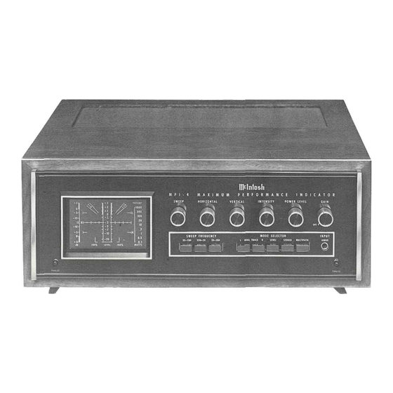
- Page 1 THE MclNTOSH MPI 4 MAXIMUM PERFORMANCE INDICATOR Reading Time 40 Minutes Price $1.25...
-
Page 3: Table Of Contents
Phone: 607-723-3512 REAR PANEL INFORMATION . . . 9 INITIAL SETUP . . . 9, 10 HOW TO USE THE MPI 4 ... 10-18 Take Advantage of 3 years PERFORMANCE LIMITS . . . 18, 19 of FREE Factory Service . . . -
Page 4: General
Mclntosh developed the PANLOC system. Pressing the facility to continuously monitor the quality of the per- formance of a stereo system. The MPI 4 can sample and dis- the two PANLOC buttons on the front panel of the MPI 4 play signals from the tuner, preamplifier and power ampli- releases the unit to slide in or out of its mounting. -
Page 5: How To Connect
There are four color-coded push connectors on the back plate over the mounting screws. The screws should panel of the MPI 4. Connect these with two pairs of speaker be centered on the "A" and "B" holes in the template. -
Page 6: How To Connect
HOW to Connect FIG. 1 CONNECTING THE MPI 4 TO STEREO RECEIVER ( T Y P I C A L C O N N E C T I O N S ) STEREO RECEIVER E N V I R O N M E N T A L E Q U A L I Z E R . - Page 7 FIG. 2. CONNECTING MPI 4 TO COMPONENT SYSTEM STEREO FM TUNER ( T Y P I C A L C O N N E C T I O N S ) E N V I R O N - M E N T A L...
-
Page 8: Front Panel Information
The MODE SELECTOR pushbuttons select the type of 5. Stereo indicators may fail to function, or function display seen on the screen of the MPI 4. Each of the five erratically. pushbuttons selects a trace—a glowing line of green light—... - Page 9 The VERTICAL control adjusts the up and down location difficult to view. By changing the timing, or sweep, of the of the trace on the screen. trace, the MPI 4 can lock onto any portion of the audio HORIZONTAL spectrum. The result is a clear, easy-to-view wave that The HORIZONTAL control adjusts the left to right loca- remains stable on the screen.
-
Page 10: Level Set Panel Information
DUAL TRACE mode of tion of the MPI 4 may be plugged into INPUT AUDIO operation. jack on the front panel. Signals are displayed on the screen SWEEP EXPANSION for observation or testing. -
Page 11: Rear Panel Information
350 watts. The outlet (deviation) of the FM signal. The trace on the screen will is not fused and is on whenever the MPI 4 power cord is expand in a horizontal direction proportional to a station's connected to an AC power outlet. -
Page 12: How To Use The Mpi 4
23. Adjust the top panel DEVIATION control to obtain the pattern shown in Figure 13. HOW to use the MPI 4 MULTIPATH MODE Multipath is caused by an FM signal arriving at your an- tenna by two (or more) paths, a direct one between an FM FIG. - Page 13 Make sure that the MPI 4 is property set up. By combining displays of strength and modulation, 1. Turn the POWER LEVEL switch to the PREAMP the MPI 4 will not only show multipath, but is, in addition, position. an accurate tuning indicator Adjust the FM tuning dial 2.
- Page 14 STEREO In this mode, the MPI 4 displays signals sampled from the preamplifier or power amplifier output. The Left chan- nel signals cause the trace to deflect in a vertical direction.
- Page 15 3. Adjust the GAIN control to obtain approximately a 2-inch display. Stereo separation is usually dictated by the program source. As you view the screen and listen to a stereo pro- gram the pattern may follow several trends. When it ex- tends outward in every direction and approximates a circle, it is indicating excellent stereo separation between chan- nels.
- Page 16 POWER LEVEL switch indicates a difference of 5 dB in power output. Turn the POWER LEVEL switch until In the SWEEP mode the MPI 4 operates as a standard you discover a position which completely contains the audio oscilloscope. In this mode it is possible to view in- peaks of the program material.
- Page 17 MPI 4 is properly centered, then: 1. Depress the STEREO button. 2. Start the phono turntable and set the pickup on the appropriate test band. 3. Ad|ust the GAIN control to obtain approximately a 2-inch display.
- Page 18 1000 Hz test tone. increase the level of the right volume if necessary. 5. Play the other tones on the test record and write Each step of the POWER LEVEL switch adds 5 dB. down the column indications for each frequency (20 dB is generally considered fair, 30 dB good and played on the test record.
- Page 19 IDEAL RIAA SYSTEM RESPONSE USING CBS STR 100 TEST RECORD 1,000 I 00 10,000 20,000 1,000 20,000 10,000 FIG. FREQUENCY IN Hz...
-
Page 20: Performance Limits
Performance Limits indicates the amplifier has low or little distortion: waveform B indicates poor linearity and clipping: while waveform C indicates crossover distortion. 6. Depress button R and observe the right channel A l l ratings are nominal waveform. MULTIPATH MODE OF OPERATION Sensitivity: l00mV/cm Frequency Response: DC to 50kHz (-3dB) Input Impedance: 250,000 W... -
Page 21: Technical Description
The first three are perma- Selectable: O n - O f f nently connected to the MPI 4, while the front panel jack provides the flexibility to observe additional signals. 3 inch round tube, c a l i b r a t e d 5 x 6cm... - Page 22 POWER SUPPLIES DC coupled amplifiers. Each consists of two cascaded There are five power supplies in the MPI 4: -5 volts; differential pairs. The input pair is a Darlington configura- + and -- 15 volts; 200 volts; and -1000 volts. Each is tion for high input impedance.
-
Page 23: Block Diagram
Block Diagram... - Page 24 MclNTOSH LABORATORY INC. 2 CHAMBERS ST., BINGHAMTON, N. Y. 13903 607-723-3512 Design subject to change without notice. Printed in U.S.A. 038-439...
Need help?
Do you have a question about the MPI 4 and is the answer not in the manual?
Questions and answers