
Related Manuals for Graf SILENTIO


Summary of Contents for Graf SILENTIO
- Page 1 User information SILENTIO“ system control „ Fill level measuring device and drinking water supply Item no.: 351022 Otto Graf GmbH Carl-Zeiss-Str. 2-6 Tel .: 07641-5890 Kunststofferzeugnisse D-79 331 Teningen Fax: 07641-58950 Page 1...
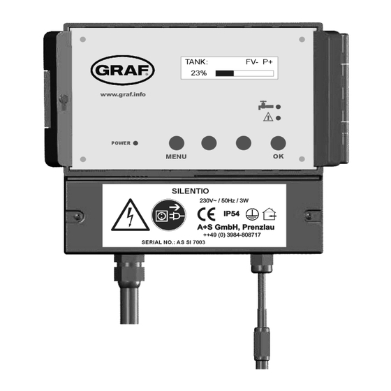
- Page 2 Figure 1: View of equipment LED for power supply display Display LED for drinking water operation LED for faults and malfunction Operating buttons Serial number Lower cover of the System Control Main connection cable with power coupling for data lead Pre-stamped breakthrough for upgrading features Mains power coupling for data lead supply cable The mains circuit breaker of the system controls are under this...
- Page 3 Figure 2: Sensor assembly Data cable screw cap 3 Connection of the data cable is reverse protected. connect white cable here connect red cable here Page 3...
- Page 4 data cable terminal screw cap 2 screw cap 1 active measuring length Stainless steel probe Tank floor Screws must be blunted ! (danger of injury) overflow Tank side in dome Sensor Sensor control box ( measurement pick-up ) 1. Safety Instructions Please read carefully the safety and instruction manual before using this device! Follow all instructions that are in the User Guide (Manual) to achieve the optimal performance.
- Page 5 1.2 Proper Use of the Device The equipment is designed exclusively for the intended purpose specified in the manual. Any other use and / or misuse of the device can lead to unpre- dictable risks including death and causes the loss of all the claims against the manufacturer.
- Page 6 1.7 Power Supply The equipment exclusively operates with the operating voltage indicated in the manual. 1.8 Cable Connection When installing the cable connections, the user needs to pay attention to the safety regulations. Always pay attention to the connection to the protective earth ground! Pay attention when connecting with other devices, that those have to be of the same earth potential (same heavy current/voltage side).
- Page 7 1.13 Cleaning Do not use any volatile solvents such as alcohol, diluents, gasoline etc. to clean the device. Only use a dry, clean cloth. 1.14 Unusual Smell If any unusual smoke or smell occurs, immediately switch off of the device and remove it from the main power supply! Contact your dealer or the manufacturer.
- Page 8 2. Description and intended use The “SILENTIO” is an electronic water management control system. It has been developed especially for rain water usage systems. It can be used with a wide variety of tank systems. Tanks made from metal or steel reinforced cement may only be used when the following conditions have been correctly followed.
- Page 9 Before opening the equipment pull the plug out from the mains socket! The system control is integrated as standard in the basic „SILENTIO“ device from the company Graf. Caution: Always remove the plug from the mains socket before opening the lower cover [7] of the system control housing!
- Page 10 Figure 3: Sensor technology Now the sensor measurement pick-up [28] (cover removed) should be installed on the tank wall (preferably in the man hole shaft of the Graf synthetic tank). The location of the mounted sensor pick-up should be between 10 and 15 cm above the overflow [25]. The enclosed screws should be used to secure the device.
- Page 11 Pass the end of the cable from the solenoid valve for the rainwater cleaning filter through the threaded grommet holder provided with the housing of the SILENTIO system control. Now open the lower housing cover [7] of the system control (see Figure 1).
- Page 12 the designation “3” (power supply to the filter flushing valve). The following figure depicts the connections described above: 1: Pump 2: Power supply to additional pump 3: Power supply to filter flushing valve 4: Power supply to switch-over valve 5: Neutral conductor P: 230V AC PE / Ground : Earth Figure 4: Electrical diagram for filter flushing valve...
- Page 13 Pass the end of the cable through the threaded grommet holder provided with the housing to the SILENTIO system control. Now open the lower cover of the system control housing (see Figure 1).
- Page 14 5. Putting into operation: Before putting into operation, please be absolutely sure that all the live wires and electrical terminals are correctly insulated and that the protective covers are in position throughout the system. Now open the transparent cover of the system control.
- Page 15 29: Status of valve for rain water filter : Filter valve open 30: Status of house water system (Pump) : Filter valve closed 31: Visual representation of fill level : House water pump running 32: Fill level % : No water being with drawn Figure 7: Display in operation 6.
-
Page 16: Default Values
Through pressing the “MENU” button again the display changes back to the operation mode. It is possible to reset the unit to the factory setting standard values at any time. The resetting can only be carried out in the operation mode (Display see Figure 6): To do this press the “ENTER”... - Page 17 SWITCHING POINTS Main menu level key „ENTER“ Supply with mains drinking water – ON (The VALVE ON numerical value is always smaller than with valve 0-100% OFF) + / - VALVE OFF Supply with mains drinking water – OFF 0-100% + / - Flush the drinking water supply piping every 14 DW INTERVAL...
- Page 18 Press the „ENTER“ button to alter the respective switching points The value to be altered will begin to blink. The value may then be adjusted by using the „+“ and the „-“ buttons. Press the “ENTER” button again when the displayed value should be accepted.
- Page 19 + / - Time scale in days; the time elapsed since the LAST RINSE last filter rinse CLEANER + / - Activation of the filter rinse HAND RINSE CLEANER + / - Depiction 12: Sub-menu “Manual functions” 7. Error messages and fault correction: The operation of the system control is to be checked at regular intervals (at the latest every 4 weeks).
- Page 20 The reason for this error is that the white ERROR sensor cable has been damaged. SENSOR Error possibilities: ERROR The data cable of the measurement pick-up DL SHORT CIRCUIT is not connected to the data cable terminal [14] but has been connected to the sensor terminal [15/16] - - Cinch plug or the cinch connector has a short circuit...
- Page 21 “AS”.( The serial number is found on the name/type label. ) 8. Upgrade options: The SILENTIO control device can also be equipped with a number of additional special functions. 1. Optional pressure sensor Using a pressure sensor, alternative mediums or depths may be adapted to the use of the device.
- Page 22 3. Optional refill If the fill level in the main tank sinks below a specified level, then a second tank is employed to back up and re fill the main tank. The pump used in this process must also be equipped with a mechanism to prevent it from running dry.
- Page 23 No diameter reduction in the drainage system according to EN 1256 Technical regulations in relation to groundwater drainage according to EN 752 Drainage systems outside of buildings according to the regulations of the local services authorities When required: Obligatory registration of the system and other man- datory stipulations 10.
- Page 24 Before opening the equipment pull the plug out from the mains socket! Depiction 14: Location of the analogue port 12. Alarm indicator contact: As an additional function, your unit is equipted with a potential-free alarm indicator contact. This contact is designed as a changeover contact element. A maximum of 230V AC is approved when a current of 1A is switched.
- Page 25 Depiction 15: Location of the fault indicator The M 12/M16 opening on the underside of the system control device must be opened and the cable drawn through. Place the supplied grommet into the opening and pass the cable through into the system control. Page 25...
- Page 26 Attachment A – Symbols used: Attention! Pull out the mains plug from the socket before opening the device. Warning of dangerous electrical voltage Attention! An error has occurred. Mains drinking water operation Page down Page up Protection classification I Only for use in a dry areas. Page 26...
- Page 27 Room for your notes: Page 27...
- Page 28 : ........Device serial number / Type : AS SI ....... Active measuring length : ........Software level SILENTIO REV : ..Design and specifications are subject to change without notice Dated: February 2018 ; Version: SI 3.4 man_Silentio_3-4_eng.odt Page 28...
Need help?
Do you have a question about the SILENTIO and is the answer not in the manual?
Questions and answers