Table of Contents
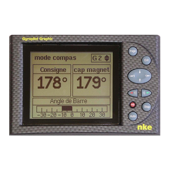
Advertisement
Advertisement
Table of Contents

Related Manuals for NKE Gyropilot Graphic

Summary of Contents for NKE Gyropilot Graphic
- Page 1 Gyropilot Graphic Command interface of the GYROPILOT 2 Product reference: 90-60-348 white / 90-60-352 carbon USER GUIDE INSTALLATION GUIDE REV 4 Sailing competition Z.I. Kerandré – Rue Gutenberg – 56700 HENNEBONT- FRANCE http://www.nke.fr – tel : +33 (0) 297 365 685.
-
Page 2: Table Of Contents
« MAN OVER BOARD » ................23 FUNCTION 1.13 GYROPILOT ..............24 OWER CONSUMPTION OF THE 2. USING THE GYROPILOT GRAPHIC IN MULTIFUNCTION DISPLAY MODE ....25 1, 2, 3 ......25 ONFIGURE YOUR DISPLAY FOR THE DISPLAY OF CHANNELS .................... 26 IST OF CHANNELS CREATED .............. - Page 3 NSTALLATION PRECAUTIONS ......................49 ALL MOUNTING NMEA ..........51 ONNECTION TO THE OPLINE BUS AND TO THE ..............52 NITIALIZATION OF THE YROPILOT RAPHIC ................ 53 NITIALIZATION OF THE PILOT INSTALLATION - 3 - Gyropilot Graphic user guide – 33-60-025-003 rev3...
-
Page 4: Using The Gyropilot Graphic In Pilot Mode
Vendée Globe, Route du Rhum and Transat the single handed raicing. The nke pilot includes: the Gyropilot Graphic, it is the user interface. It allows to control the pilot and adjust the settings, the Gyropilot 2 calculator, which is the brain of the pilot, the hydraulic unit or electrical unit, which provides the power to actuate the boat’s rudder,... - Page 5 Gyrop lot 2 Calculateur Gyro2 DATA black 12VDC white Embrayage Pompe Alim. Anemovane Angle réversible Tiller TOPLINE cable Barre 20-61-001 Helm spindle Rudder angle hydraulic ram Figure 1 - 5 - Gyropilot Graphic user guide – 33-60-025-003 rev3...
-
Page 6: General Operation Of The Gyropilot Graphic
1.2 General operation of the Gyropilot Graphic The Gyropilot Graphic display is designed to control your pilot and your system. The performance of the Gyropilot is excellent at any sailing speed. It will assist the helmsman effectively, but must not be used as the primary means to navigate. -
Page 7: Functions Of The Keys Of Gyropilot Graphic Display
1.3 Functions of the keys of Gyropilot Graphic Display Page Pressing this key allows you to select the pilot page, the multifunction display page or the menu page. It also allows to leave the setting menus, without performing a backup. -
Page 8: First Startup Of The Pilot
1.4 First startup of the pilot This first part of the guide explains how to use the Gyropilot Graphic, on the basis that it is installed and initialised. If that is not the case please refer to the installation chapter of this guide. - Page 9 The Gyropilot uses very little energy (a few tens of milliamps) when the pilot is disengaged. Hence when you are sailing and the pilot is disengaged, it is not necessary to cut off the power supply of the pilot to save energy. - 9 - Gyropilot Graphic user guide – 33-60-025-003 rev3...
-
Page 10: Description Of The Five Operating Modes
These five modes will be accessible on the Gyropilot Graphic depending on the level of your installation: The compass mode requires a speedometer log sensor and a compass sensor. - Page 11 Topline magnetic heading channel, The pilot gain window is common to the five modes. The Rudder angle window is common to the compass, apparent wind, true wind and rudder modes. - 11 - Gyropilot Graphic user guide – 33-60-025-003 rev3...
- Page 12 True wind mode is more particularly effective down wind with a strong swell: it is under these sailing conditions that the nke Gyropilot demonstrates its best capabilities. Down wind and in the swell, if you use apparent wind mode, you will notice the following: When the boat goes down wave, the apparent wind speed increases, the apparent wind angle decreases and thus the wind hauls forward.
- Page 13 Gyropilot Graphic. To obtain the « true wind option » code, please contact your nke distributor. Since this code is unique for each Gyropilot 2 calculator, you must communicate the serial number of your instrument to your distributor.
- Page 14 WAYPOINT is correct. He then presses the AUTO key once more: this will enable the GPS mode once again, directing the boat towards the next WAYPOINT. The procedure is repeated for each new WAYPOINT. - 14 - Gyropilot Graphic user guide – 33-60-025-003 rev3...
-
Page 15: Pilot Setting Menu: Optimising The Performances Of The Pilot
Tacking speed Rudder offset Speed coefficient time before stop Rudder offset Save configuration => time before stop Load configuration <= Save configuration => speed ref surface Man over board crew - 15 - Gyropilot Graphic user guide – 33-60-025-003 rev3... - Page 16 By default, the value is set at 100°. The speed of rotation during tacking manoeuvres under pilot control can be set between 1 and 32. By default, the value is set at 9. - 16 - Gyropilot Graphic user guide – 33-60-025-003 rev3...
- Page 17 This time lag is used to force the pilot to keep control of the rudder in case of a communication breakdown with the TOPLINE bus. The time lag is adjustable between 6 and 60 seconds, and the default value is 6 seconds. - 17 - Gyropilot Graphic user guide – 33-60-025-003 rev3...
- Page 18 If your pilot is equipped with the True Wind option, this function allows to select the reference speed of the calculator. You can select bottom speed or surface speed. It is only to calculate at each movement the helm angle in accordance with the speed. - 18 - Gyropilot Graphic user guide – 33-60-025-003 rev3...
-
Page 19: Protect Your Settings With A Owner Code
Graphic is delivered with no security code and thus all the settings are accessible. Note that this function is only available on the Gyropilot Graphic, and that the settings can be modified from another multifunction display connected to the bus. -
Page 20: Performing A Tacking Or Jibing Manoeuvre Under Pilot Control
0 = no lighting, 1 corresponds to the minimum level of lighting and 4 to the maximum level. You have the option to adjust the level of lighting, either solely on the Gyropilot Graphic, or on every TOPLINE display of your installation: 1.9.1 Setting for the Gyropilot Graphic... - Page 21 , choose the required menu as well as level and press ENT. To have this screen, you can , also , press on the ENT key when you are on the AUTOPILOT page - 21 - Gyropilot Graphic user guide – 33-60-025-003 rev3...
-
Page 22: Setting The Alarms Of The Pilot
Please note that the battery power alarm is constantly activated. 1.10.3 Suspending an alarm When an alarm is triggered, you can suspend the alarm for 10 minutes by briefly pressing the Ent key. - 22 - Gyropilot Graphic user guide – 33-60-025-003 rev3... -
Page 23: Operation Of The Gyropilot In Degraded Mode
The Gyropilot engages the pilot in rudder mode, and positions the rudder with a +/- 40° set point, depending on the previous position of the rudder. In the pilot setting menu, select the submenu Man over board, and choose the crew mode or the alone mode. - 23 - Gyropilot Graphic user guide – 33-60-025-003 rev3... -
Page 24: Power Consumption Of The Gyropilot
The voltage of the power battery of the pilot is also available through the pilot voltage channel. Please note that the consumption is highly dependent on the sea conditions and the trim. - 24 - Gyropilot Graphic user guide – 33-60-025-003 rev3... -
Page 25: Using The Gyropilot Graphic In Multifunction Display Mode
2. USING THE GYROPILOT GRAPHIC IN MULTIFUNCTION DISPLAY MODE The Gyropilot Graphic is a Multifunction display of the TOPLINE range. Its graphic screen offers excellent readability and a wide angle of view of the data displayed, whether by daylight or at night. It is connected to the TOPLINE bus of your installation and will display data on the bus. -
Page 26: List Of Channels Created
2.2 List of channels created The master display, whether it is the Gyropilot Graphic or any other TOPLINE display, and each TOPLINE sensor, automatically create their respective channels when they are connected to the TOPLINE bus. Please refer to the user guides of the sensors and instruments to identify their channels. -
Page 27: Configuring The Display Of The Channels
Page key. 2.3 Configuring the display of the channels The display Windows of the Gyropilot Graphic are independent. Configure the channels according to your requirements: Example, you want to replace the channel boat speed by the channel depth :... -
Page 28: What Is A Sub-Channel
Using the Page key, select the Main menu page, then using the browser , select Alarms, then TOPLINE setting, press the Ent key, select surface speed in the list of channels, then press the Ent key, - 28 - Gyropilot Graphic user guide – 33-60-025-003 rev3... - Page 29 TOPLINE ON/OFF (see above), then press the Ent key. 2.6.3 Suspending an alarm Please note that when an alarm is triggered, you can suspend the audible alarm for 10 minutes, by briefly pressing the Ent key. - 29 - Gyropilot Graphic user guide – 33-60-025-003 rev3...
-
Page 30: Filtering (Damping) Of The Channels
Ent key, or exit by pressing the Page key. - 30 - Gyropilot Graphic user guide – 33-60-025-003 rev3... -
Page 31: Zero Setting Of The Day Trip And Total Trip
It is performed by initializing the boat speed channel. During this operation, the settings of the speedometer, log, depth and water temperature are reset to the default factory values. - 31 - Gyropilot Graphic user guide – 33-60-025-003 rev3... -
Page 32: Choice Of Languages
Ent key to validate your selection or exit by pressing the Page key. 2.11 Use of the Race Timer The Gyropilot Graphic includes a regatta chronometer. Times by default are T1= 6min and T2 = 4min. 2.11.1 Preparing and starting the race timer... -
Page 33: Nmea Link
2.12 NMEA LINK The Gyropilot Graphic includes an NMEA input, allowing the connection of a GPS or any other instrument providing NMEA frames : PC, meteorological sensors, etc. After performing the NMEA initialization of the Gyropilot Graphic, the NMEA channels corresponding to the frames transmitted by the instrument are available on the TOPLINE bus. - Page 34 Heading at next leg ANGLE_OPT_VENT, REND_PRES, $PNKEP,03 Optimum upwind angle REND_POLAIRE. Angles to optimise the CMG and VMG and ANGLE_OPT_CMG, ANGLE_OPT_VMG, $PNKEP,04 gain GAIN_ROUTE_CMG, GAIN_ROUTE_VMG. $PNKEP,05 Current direction and speed DIREC_COURANT, VITES_COURANT. - 34 - Gyropilot Graphic user guide – 33-60-025-003 rev3...
-
Page 35: The Nmea Console: A Tool To Visualise The Nmea Frames
2.13 The NMEA console: a tool to visualise the NMEA frames The NMEA console of the Gyropilot Graphic allows to read the NMEA frames, which are provided by the instrument which is connected (GPS, PC, barometer). Thus, the NMEA console works out to be a practical tool for setting up your installation. -
Page 36: Diagnostic For
(black) is in short-circuit » box: see installation chapter. The Gyropilot Graphic display three dashes «- - -» in place of Check the sensor of this channel, check the connection cable: it may be the data of a channel. -
Page 37: Sensor Calibration
3. SENSOR CALIBRATION Every nke sensor is adjusted at the factory. However, a calibration is required to adapt the sensor to the specificities of your boat and to obtain an optimum measurement accuracy. Follow the calibration procedure below, by visualising the settings on a display. -
Page 38: Offset Setting
Page key. * For the previous generation of compass, referenced as 90-60-005, at least three circles must be executed. - 38 - Gyropilot Graphic user guide – 33-60-025-003 rev3... -
Page 39: Setting The Depth-Finder Blanking
To return to the menu press page validate : ENT Menu: PAGE In case of problem during autocompensation, the Gyropilot Graphic displays the following error messages: Cancellation at user request. Detection of a gyration in the opposite direction. Start again clockwise. -
Page 40: Calibration Utilities
Gyropilot Graphic. To obtain the « Calibration utilities » code, please contact your nke distributor. Since this code is unique for each Gyropilot Graphic, you must communicate the key number of your instrument to your distributor. -
Page 41: Automatic Calibration Of Boat Speed
0.5 Nm each Cancel: PAGE Continue: ENT Press Ent once again, the following page is displayed: Follow a COG Press ENT Boat speed X.XX X.XX XXX° Cancel: PAGE Start: ENT - 41 - Gyropilot Graphic user guide – 33-60-025-003 rev3... - Page 42 Ent, the following page is displayed: COG to follow ° Boat Loch X.XX Over Ground Loch X.XX Boat speed X.XX X.XX XXX° Cancel: PAGE End ENT - 42 - Gyropilot Graphic user guide – 33-60-025-003 rev3...
-
Page 43: Calibration Of The Nke Compass Based On The Correction Table
4.3.1 Principle This involves manually or automatically completing a correction table. This correction table allows the headings of the nke compass to be corrected every 30°. 4.3.2 Manual calibration of the nke compass. The method consists in plotting the deviation curve every 30°, by performing plots on alignments, or by... - Page 44 4.3.3 Procedure for manual calibration of the nke compass Using the Page key, select the Main menu page, Then using the browser , select Configuration then calibration, Press Ent, In the list of channels, select Compass head, then press Ent,...
- Page 45 Ent. Repeat this operation every 30° in order to complete the correction table. Once this correction table is complete, your compass is corrected of deviation curve. 4.3.4 Procedure for automatic calibration of the nke compass Using the Page key, select the Main menu page, Then using the browser...
-
Page 46: Calibration Of Apparent Wind Angle
REF HEADING XX° XXX° Cancel: PAGE Confirm: ENT Maintain the required nke compass heading at ± 10°, then plot the reference heading mag.(COG) and enter it using the browser , then press Ent, the following page is displayed: Record correction? Old correction: XX°... - Page 47 Ent to stop recording, then change tack so as to come to close-hauled port tack. The following window is displayed: Calibration app wind angle Port Starboard Offset XX°< >XX° Cancel:PAGE Stop:ENT - 47 - Gyropilot Graphic user guide – 33-60-025-003 rev3...
-
Page 48: Installation
, then press Ent. Otherwise, press Ent. 5. INSTALLATION This chapter describes the installation and initialisation of the Gyropilot Graphic. It also describes the complete initialisation of the Gyropilot. The general installation of the pilot (ram, computer, rudder angle, etc.) is described in the Gyropilot computer guide. -
Page 49: Installation Precautions
Lay a thin silicone sealing joint around the mounting perimeter, introduce the cable in the 17 drilled hole, position the display then tighten the fixing nut moderately. - 49 - Gyropilot Graphic user guide – 33-60-025-003 rev3... - Page 50 Figure 2 CAUTION : When mounting the display, tighten the nut moderately. Excessive tightening can cause the casing to break. Do not use glue putty to mount the display. - 50 - Gyropilot Graphic user guide – 33-60-025-003 rev3...
-
Page 51: Connection To Thet
5.5 Connection to the Topline bus and to the NMEA bus Make the bus cable run from the Gyropilot Graphic to the TOPLINE terminal box of your installation. Connect the bus cable inside the terminal box. Gyropilote Graphic mode vent reel... -
Page 52: Opline Bus And To The Yropilot Graphic
5.6 Initialization of the Gyropilot Graphic At first power-up, you must initialize the Gyropilot Graphic so that an address is assigned to it. The display is delivered with the address set as 0. During the initialization, it will automatically insert itself in the list of instruments of the TOPLINE bus of your installation:... - Page 53 These three rudder positions are essential for the good operation of the drive unit of the pilot. Follow the menu « Pilot Initialization » of the Gyropilot Graphic which will guide you along the procedure. Procedure...
- Page 54 NOTES _____________________________________________________________________________________________________ _____________________________________________________________________________________________________ _____________________________________________________________________________________________________ _____________________________________________________________________________________________________ _____________________________________________________________________________________________________ _____________________________________________________________________________________________________ _____________________________________________________________________________________________________ _____________________________________________________________________________________________________ _____________________________________________________________________________________________________ _____________________________________________________________________________________________________ _____________________________________________________________________________________________________ - 54 - Gyropilot Graphic user guide – 33-60-025-003 rev3...
- Page 55 NOTES _____________________________________________________________________________________________________ _____________________________________________________________________________________________________ _____________________________________________________________________________________________________ _____________________________________________________________________________________________________ _____________________________________________________________________________________________________ _____________________________________________________________________________________________________ _____________________________________________________________________________________________________ _____________________________________________________________________________________________________ _____________________________________________________________________________________________________ _____________________________________________________________________________________________________ _____________________________________________________________________________________________________ - 55 - Gyropilot Graphic user guide – 33-60-025-003 rev3...
Need help?
Do you have a question about the Gyropilot Graphic and is the answer not in the manual?
Questions and answers