
Related Manuals for Black Box EFN06-24


Summary of Contents for Black Box EFN06-24
- Page 1 © Copyright 2000. Black Box Corporation. All rights reserved. 1000 Park Drive • Lawrence, PA 15055-1018 • 724-746-5500 • Fax 724-746-0746...
- Page 2 Order toll-free in the U.S. 24 hours, 7 A.M. Monday to midnight Friday: 877-877-BBOX SUPPORT FREE technical support, 24 hours a day, 7 days a week: Call 724-746-5500 or fax 724-746-0746 INFORMATION Mail order: Black Box Corporation, 1000 Park Drive, Lawrence, PA 15055-1018 Web site: www.blackbox.com • E-mail: info@blackbox.com...
-
Page 4: Table Of Contents
CONTENTS Contents 1. Specifications ..........2 2. -
Page 5: Specifications
6- OR 12-BUFFER TUBE FANOUT KIT 1. Specifications Buffer Tube Diameter—6-Fiber Buffer Tube Fanout: 2.4-mm buffer tubes; 12-Fiber Buffer Tube Fanout: 3.0-mm buffer tubes Protective Tube Diameter—900 µm Temperature—32 to 158°F (0 to 70°C) -
Page 6: Introduction
CHAPTER 2: Introduction 2. Introduction 2.1 Description Because individual fiber optic cable strands have an extremely small diameter, to terminate the cable you must first enclose each strand in protective tubing. Once the cable is enclosed, you can then add fiber optic connectors, such as SC, to each enclosed cable. -
Page 7: Precautions
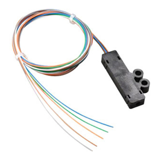
2.3 What the Package Includes Check to make sure your package includes the following items (refer to Figure 2-1). If anything is missing or damaged, please contact Black Box at 724-746-5500. Buffer Tube Fanout top ➁... -
Page 8: What You Need To Supply
CHAPTER 2: Introduction ➂ ➁ Figure 2-1. Package Contents. 2.4 What You Need to Supply You’ll need the following items: • Electrical tape • Lint-free tissues • Clean rags • Permanent marker • Wire markers • Buffer tube stripper • Buffer tube clamps •... -
Page 9: Installation
6- OR 12-BUFFER TUBE FANOUT KIT 3. Installation 3.1 Preparing the Cable CAUTION Read the cable manufacturer’s sheath-removal instructions. Some cable-stripping procedures may call for a slightly longer length at the end of the cable to allow for cable core (buffer tube) damage caused when accessing rip cords, etc. - Page 10 CHAPTER 3: Installation Permanent routing Rack Temporary cable routing to work surface Buffer Tube Fanout taped to work surface Figure 3-1. Option 1. Option 2 1. Prepare the cable end. 2. Mount the cable on the hardware. 3. Route the buffer tubes to a work surface. 4.
- Page 11 6- OR 12-BUFFER TUBE FANOUT KIT Determine the total strip length requirement for your installation. This length will be: • The buffer tube length(s) required to route the tubes from the cable sheath attachment point to the planned location of the Buffer Tube Fanout body. plus •...
- Page 12 CHAPTER 3: Installation Strip length Tape Figure 3-3. Cable Strip Length. Strip the cable according to the cable manufacturer’s instructions for removing the sheath. Determine the cable central member and strength member yarn lengths needed to secure the cable from the instructions provided with the hardware.
-
Page 13: Preparing The Buffer Tube
6- OR 12-BUFFER TUBE FANOUT KIT 3.2 Preparing the Buffer Tube 1. Tape the cable end to a work surface so that the marks on the buffer tubes can reach the work surface edge (see Figure 3-4). 2. Select the first buffer tube. Use a buffer stripping tool to remove the buffer tube back to the mark made in permanent marker. -
Page 14: Threading The Fibers
CHAPTER 3: Installation IMPORTANT Make sure that the fibers are clean and dry. Any residue left on the fiber will obstruct threading operations into the 900-µm assembly pieces. 6. Place the crimp tabs of the bottom piece of the Buffer Tube Fanout on the end of the buffer tube. - Page 15 6- OR 12-BUFFER TUBE FANOUT KIT 3. Carefully thread about three inches of the first fiber into the #1 slot of the 900-µm tube (see Figure 3-7). 1) Blue Top view 2) Orange 3) Green 4) Brown 5) Slate 6) White 7) Red 8) Black 9) Yellow...
- Page 16 CHAPTER 3: Installation 6. Carefully pull the fibers out of the tube ends to take up most of the excess length between the Buffer Tube Fanout body and the 900-µm assembly. NOTE Leave a small fiber loop between the Buffer Tube Fanout body and the 900-µm assembly to prevent fiber breakage during later steps in this procedure (see Figure 3-8).
- Page 17 6- OR 12-BUFFER TUBE FANOUT KIT NOTE Because buffer tubes are semi-rigid, they require careful handling to compensate for their “memory” and “springy” nature. Buffer tubes will tend to quickly return to their original position after handling. Whenever you use tape to anchor the tubes down, use care to control the tubes when removing the tape.
-
Page 18: Marking The Buffer Tube Fanout
CHAPTER 3: Installation NOTE We recommend working with the tubes in sequential order to maintain installation organization. 3.4 Marking the Buffer Tube Fanout To aid in the identification and maintenance of the fanout assemblies, use numbered wire markers. These markers can individually identify each Buffer Tube Fanout with respect to its buffer tube number if the buffer tubes are not easily distinguished (see Figure 3-12). -
Page 19: Installing The Buffer Tube Fanout Into Hardware
6- OR 12-BUFFER TUBE FANOUT KIT 3.6 Installing the Buffer Tube Fanout into Hardware 1. You can either bolt or tape the Buffer Tube Fanout into pieces of hardware. Refer to the instructions provided with the hardware you’re using to determine the best method.