
Summary of Contents for Vatech pDRIVE CX profi
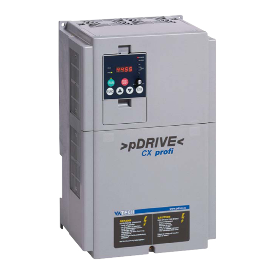
- Page 1 VA TECH ELIN EBG Elektronik Operating and Mounting instructions >pDRIVE< CX profi The Power Drives Company...
-
Page 2: Parameters
Safety instructions General information, note exactly ! The requirements for a successfull commissioning are a correct selection of the unit, projection and mounting. In case of further questions, please contact the supplier or call the manufacturer of the unit directly. Capacitor discharge ! Before any work on or in the unit, disconnect from the mains and wait at least 5 minutes until the D.C.link capacitors have been fully discharged. - Page 3 Operating and Mounting the Frequency inverter >pDRIVE< CX profi 11...37 kW, 3 AC 380...480 V Topic Page Operating Parameters Displays Projecting Mounting Connection Options Start-up Log Appendix A This manual includes the topics operating, description of parameters and displays, projecting, mounting, connection and options. Regulations for the observance of the CE-directive and the new Power-Drive-Standard (EN 61800-3) are described in chapter “CE Marking”.
-
Page 4: Displays
Operating using the control panel built-in Description of the control panel Configurable LED display RUN button starts the inverter when it POTENTIOMETER is not controlled via the to adjust the frequency. terminal strip The LED lights up as soon as the frequency can be set using the potentiometer STOP/RESET button... -
Page 5: Mounting
Example of programming to set the frequency and to start the inverter Operating & Mounting instructions – 8 074 143.03/03 – Page 3... - Page 6 LEDs on the control panel Power-LED Alarm-LED RUN-LED Hz-LED PRG-LED V-LED A-LED RUN-button %-LED POTI-LED Power-LED: lights up when the inverter is connected to mains supply, that means there is a voltage. Alarm-LED: lights up in case of a trip at the inverter. Hz-LED: indicates that the value of the display shows frequency in hertz.
- Page 7 Overview of control levels Operating & Mounting instructions – 8 074 143.03/03 – Page 5...
- Page 8 Changing the indication of the LED display: 1.) Switch to the 1st user level using the FUNC button. 2.) Use the UP/DOWN buttons to select the required display. 3.) Press the STR button to confirm the selection and to return to the display level. Changing parameter settings on the 1st control level: 1.) Switch to the 1st control level using the FUNC button.
-
Page 9: Parameter Name
Overview of parameters The following overviwe shows all parameters arranged according to their functions. Display actual values Factory Parameter name Adjusting range default page d001 Output frequency read only d002 Output current read only d003 Direction of rotation read only d004 PID controller feedback read only d005 Condition of digital inputs... - Page 10 Analog inputs Factory Parameter name Adjusting range default page A011 External frequency start O (0...10V) 0,00...400,0 Hz 0,00 Hz A101 External frequency start OI (4...20mA) 0,00...400,0 Hz 0,00 Hz A111 External frequency start O2 (-10...+10V) -400,0...+400,0 Hz 0,00 Hz A012 External frequency end O (0...10V) 0,00...400,0 Hz 0,00 Hz A102 External frequency end OI (4...20mA)
- Page 11 V/f characteristic Factory Parameter name Adjusting range default page A041 Torque boost method selection 00 or 01 A042 Manual torque boost setting 0,0...20,0 % 1,0 % A043 Manual torque boost frequency point 0,0...50,0 % 5,0 % A044 V/f characteristic setting 00 to 02 A045 Voltage gain setting 20...100 %...
- Page 12 Frequency limits Factory Parameter name Adjusting range default page A061 Frequency upper limit 0,00...400,0 Hz 0,00 Hz A062 Frequency lower limit 0,00...400,0 Hz 0,00 Hz A063 1st Jump frequency 0,00...400,0 Hz 0,00 Hz A064 1st Jump frequency width 0,00...10,0 Hz 0,50 Hz A065 2nd Jump frequency 0,00...400,0 Hz...
- Page 13 Thermal protection Factory Parameter name Adjusting range default page b012 Electronic overload setting 0,2...1,2 x I FI-I b013 Electronic overload characteristic 00 to 02 b015 Free electronic thermal: frequency 1 0...400 Hz 0 Hz b016 Free electronic thermal: current 1 0,0...1000 A 0,0 A b017...
-
Page 14: Table Of Contents
Digital outputs Factory Parameter name Adjusting range default page C021 Function of relay 11 00 to 13 C022 Function of relay 12 00 to 13 C026 Function of relay AL 00 to 13 C031 Relay output 11: Inversion 00 or 01 C032 Relay output 12: Inversion 00 or 01... - Page 15 2nd Set Factory Parameter name Adjusting range default page A203 2nd Base frequency 30...400 Hz 50 Hz A204 2nd Maximum Frequency 30...400 Hz 50 Hz F202 2nd Acceleration ramp 0,01...3600 s 30 s F203 2nd Deceleration ramp 0,01...3600 s 30 s A220 2nd Internal pre-set speed 0,00...400,0 Hz 0,00 Hz...
- Page 16 Serial communication Factory Parameter name Adjusting range default page RS485 C070 Data command 02 to 05 C071 Transmission speed 02 to 06 C072 Identification code 1...32 C073 Data bits 7 or 8 C074 Parity 00 to 02 C075 Number of Stop bits 1 or 2 C078 Waiting time 0...1000 ms...
- Page 17 Commissioning Before working with the equipment check following points: 1.) Check that mains supply and motor cables are connected properly. 2.) Are the control lines properly connected to the right terminals ? 3.) s the frequency inverter properly grounded and assembled ? 4.) Remove installation residues, such as cable residues, in order to avoid short circuits.
- Page 18 Description of parameters The parameters of the >pDRIVE< CX are arranged and described according to their functions. The following example explains the attributes of parameters: A038 Jogging frequency 0,0...9,9 Hz 1,0 Hz Factory default Name of parameter Number of parameter Adjusting range Group of parameter Parameter description:...
- Page 19 d005 Condition of digital inputs read only Status display (ON/OFF) of digital inputs on the LED display. EIN/ON (24 V) EIN/ON (24 V) AUS/OFF (0 V) AUS/OFF (0 V) Eingangsnr.: 5 4 3 2 1 Input No.: d006 Condition of digital outputs read only Status display (ON/OFF) of digital outputs on the LED display.
- Page 20 Base settings Get Started A003 Base frequency 30...400 Hz 50 Hz Adjustment of the base frequency. The base frequency is the frequency at which the output voltage reaches its maximum value. Normally, the base frequency is equal to the nominal motor frequency. A004 Maximum frequency 30...400 Hz...
- Page 21 A001 Method of speed command 00 to 05 Setting Reference via Potentiometer on the keypad Control terminals (analog inputs or multi speeds) Parameter F001, A020/A220 or motorpotentiometer RS 485 Option 1 Option 2 A002 Method of run command 01 to 05 Setting Control command via Control terminals (FW, REV inputs)
- Page 22 A014 Analog signal reference for end O (0...10V) VIC 0...100 % 100 % A104 Analog signal ref. for end OI (4...20mA) 0...100 % 100 % A114 Analog signal ref. for end O2 (-10...+10V) -100...+100 % 100 % This parameters define the maximum reference value if it should be other than 10 V, 20 mA or +10 V.
- Page 23 A005 AT Terminal selection 00 or 01 Setting Function Switching between 0...10V and 4...20mA (O / OI) Switching between 0...10V and -10...+10V (O / O2) A006 O2 Control selection 00 to 02 Setting Function Single reference value (without f-correction) Addition of f-correction without changing direction Addition of f-correction with change of direction Parameter Terminal...
- Page 24 C081 Adjustment 0...10 V input 0...9999 Default C082 Adjustment 4...20 mA input 0...9999 Default C083 Adjustment -10...+10 V input 0...9999 Default C121 Offset-adjustment 0...10 V input 0...9999 Default C122 Offset-adjustment 4...20 mA input 0...9999 Default C123 Offset-adjustment -10...+10 V input 0...9999 This adjustments are done in factory and should not be changed! Multispeeds...
- Page 25 Multi speeds − “binary” function CF1 CF2 CF3 CF4 Adjusted value Parameter Internal preset speed if A001=02 A020 Multispeed 1 A021 Multispeed 2 A022 Multispeed 3 A023 Multispeed 4 A024 Multispeed 5 A025 Multispeed 6 A026 Multispeed 7 A027 Multispeed 8 A028 Multispeed 9 A029...
- Page 26 V/f characteristic A041 Torque boost method selection 00 or 01 Setting Function manual boost automatic boost A042 Manual torque boost setting 0,0...20,0 % 1,0 % A043 Manual torque boost frequency point 0,0...50,0 % 5,0 % For applications which require higher starting torque, the standard starting torque can be increased. Use parameter A041 to select between automatic and manual boost.
- Page 27 A045 Voltage gain setting 20...100 % 100 % The output voltage can be set within the range of 20...100 % of the motor voltage set with parameter A082. b036 Start reduced voltage selection 00 to 06 With this parameter the control time of the start voltage is set. Setting 00 .......
- Page 28 Free adjustable V/f characteristic: DC brake Braking The frequency inverters >pDRIVE< CX profi have an adjustable DC brake. By locking a clocked DC rotor voltage onto the base of the motor, the rotor produces a braking torque that counteracts the rotation. With the help of the DC brake, braking a drive to minimum speed is possible, before the mechanical brake is activated.
- Page 29 Parameter A055 and A058 define the duration of DC injection braking. The value is set within the range from 0,1 to 60 seconds. Parameter A056 defines wheter the DC brake is active depending on time or depending on a contact. Parameter A059 defines the carrier frequency during DC braking.
- Page 30 DC brake controlled via digital input (A051=00) The DC brake is activated via a digital input (D8: C001...C005=7). Note: The DC brake causes a heating of the connected motor. Be sure that the motor does not get to warm. Operating & Mounting instructions – 8 074 143.03/03 – Page 28...
- Page 31 b090 Dynamic braking ratio 0,0...100,0 % 0,0 % Adjusting the allowed duration time of the braking resistor (only at CX profi 11 and 15). Setting 0,0 % means that the internal braking unit is not active. b095 Dynamic braking selection 00 to 02 Setting Function...
- Page 32 A063 1st Jump frequency 0,00...400,0 Hz 0,00 Hz A064 1st Jump frequency width 0,00...10,0 Hz 0,50 Hz A065 2nd Jump frequency 0,00...400,0 Hz 0,00 Hz A066 2nd Jump frequency width 0,00...10,0 Hz 0,50 Hz A067 3rd Jump frequency 0,00...400,0 Hz 0,00 Hz A068 3rd Jump frequency width...
- Page 33 PID reference value The reference value is selected using parameter A001. The following values can be used as reference source: Reference value Settings Standardization Potentiometer built-in A001 = 00 0...100 % Parameter value F001 A001 = 02 0...100 % x Parameter A075 Multispeeds A020...A035 0...100 % x Parameter A075 Analog input O (0...10 V)
- Page 34 A071 Selection of PID function: ON/OFF 00 or 01 The PID controller is activated and deactivated using parameter A071. Setting Function PID controller not active PID controller active; with digital input to setting 23 (PID enable) switch-over to manual control *) After setting the scale conversion (parameter A075) this parameters are adjusted and displayed in process sizes.
- Page 35 A075 PID controller: Scale conversion 0,01...99,99 1,00 Parameter A075 allows the setting of a conversion factor for the proper process presentation of the PID reference and actual value on the LED display. Parameters A011 (A101), A012 (A102), d004, F001 and A020...A035 are converted in accordance with the setting of A075.
- Page 36 A081 Selection of AVR function 00 to 02 Parameter A081 switches the “Automatic Voltage Regulation” for the motor on and off. Setting Function AVR function active AVR function not active AVR function not active during deceleration A082 Selection of voltage for AVR 380...480 V 400 V The nominal motor voltage (380 / 400 / 415 / 440 / 460 / 480 V) is set with parameter A082.
- Page 37 A095 Switch-over 1./2. acceleration ramp 0,00...400,0 Hz 0,00 Hz A096 Switch-over 1./2. deceleration ramp 0,00...400,0 Hz 0,00 Hz Particularly, this switch-over is used for EMERGENCY STOP functions and speed-related acceleration and deceleration times. The adjusted acceleration/deceleration time is related to the maximum frequency A004.
- Page 38 Thermal protection Electronic Overload b012 Electronic overload setting 0,2...1,2 x I FI-I A thermal motor contactor (“maximum continuous current”) can be set by entering the nominal motor current in A. Note: If the value is higher than the nominal motor current, the motor cannot be protected by an electronic motor contactor.
- Page 39 Overload protection Overload restriction b021 Selection of 1st overload restriction 00 to 02 This parameter defines when the current limitation is active. Setting Function not active during acceleration and constant speed only at constant speed Note: The overload restriction is not active during deceleration. b022 Level of 1st overload restriction 0,5...1,5 x I...
- Page 40 Digital inputs Input terminals C001 Function of input 1 01 to 39, NO C002 Function of input 2 01 to 39, NO C003 Function of input 3 01 to 39, NO C004 Function of input 4 01 to 39, NO C005 Function of input 5 01 to 39, NO...
- Page 41 Explanations of the functions for the digital inputs Start/Stop via switch contacts: When the contacts are closed, a Start command is 00 Start FWD issued in the right direction (acceleration on gradient), when open, a stop command is issued (deceleration on gradient). The simultaneous 01 Start REV closing of Start forward and Start reverse also issues a Stop command to the inverter.
- Page 42 DC brake: 07 DC brake If this command is activated, the DC brake is active. Switch-over of parameters: If this command is activated, the inverter switches over to the 2nd set of parameters. Motor data, 08 2nd Set minimum and maximum limits and the accelerati- on and deceleration times are switched over.
- Page 43 External fault: The activated command leads to immediate fault shut-down with the error message „E12 - Ext. fault“. Using this input, plant errors can be 12 Ext. fault integrated in the control of the frequency inverter. The error message cn be realised using the break or make contact (parameter C011 to C015).
- Page 44 Bypass signal: 14 Bypass signal An activation of the command leads an holding of the running motor after mains operaiton. Verriegelungszeit/ Bypaßschütz/ Cut-off time bypass contactor Motorschütz/ Motor contactor Netzschütz/ Mains contactor 0,5...1s Ausgangsfreq./ Output freq. b003 After the switch-over from bypass to inverter ope- ration, the inverter takes over the running motor after the waiting time set with parameter b003.
- Page 45 External reset: Allows you to confirm an error via the terminals. During operation, an external Reset-command stops the inverter!! The signal must not be inverted and must not be issued for more than 4 seconds. 18 External reset A permanent reset is not possible. If the inverter is running without problems, it runs to 0 Hz when an RS signal is issued! In plants, where a common reset signal is used for all devices, parameter...
- Page 46 Multispeeds (“bit”-function): The multispeeds (maximum 7) are selected using the signals SF1...SF7 according to the table: SF1 SF2 SF3 SF4 SF5 SF6 SF7 Ref. value 32 Fix 1 analog value 1 (A021) 33 Fix 2 2 (A022) 3 (A023) 34 Fix 3 4 (A024) 5 (A025) 35 Fix 4...
- Page 47 C011 Condition of input C001 00 or 01 C012 Condition of input C002 00 or 01 C013 Condition of input C003 00 or 01 C014 Condition of input C004 00 or 01 C015 Condition of input C005 00 or 01 C019 Condition of input FW 00 or 01...
-
Page 48: C021 Function Of Relay
Digital outputs Output terminals C021 Function of relay 11 00 to 13 C022 Function of relay 12 00 to 13 C026 Function of relay AL 00 to 13 The programmable relay outputs (terminals 11 and 12 and also AL) can be programmed using parameters C021, C022 and C026. - Page 49 Funktion FA1: C021, C022 oder/or C026 = 1 Funktion FA2: C021, C022 oder/or C026 = 2 “Sollwert erreicht” / “Reference value arrival” “Frequenz überschritten” / “Frequency exceeded” 1.5 Hz 0.5 Hz C042 0.5 Hz 1.5 Hz C043 0.5 Hz 1.5 Hz Ausgangs- Output signal...
-
Page 50: C032 Relay Output
Function: A A L C021, C C 022 o o r C C 026 = = 0 0 5 “Error m m essage” If one of the outputs C021 or C022 is set to position 05, an error signal is issued if an error occurs. During mains failure the error signal will continue only as long as there is still power in the inverter. -
Page 51: C042 Arrival Signal For Acceleration
Output functions Output functions C040 Overload signal output mode 00 or 01 Setting Function Message during acceleration and constant frequency Message only at constant frequency C041 Level of overload signal 1 0...2 x I Setting the parameter within a range of 0 to 200 % with reference to the nominal current of the inverter. -
Page 52: Sec 1,0 Sec
C061 Level of thermal motor protection 0...100 % 80 % This parameter defines the level, at which the alarm message “Temperature alarm” occurs at the digital output. If this parameter is set to 0 %, the function is not active. b034 Run/Power on time 0...9999... - Page 53 In the event of a low-voltage trip during operation, e.g. mains failure, the inverter switches to impulse lock. If the voltage returns within the time set with b002, the inverter can be started again. Otherwise, the unit shuts down with the message undervoltage. If parameter b001 is set to 01, the time period b003 can be set after which the frequency inverter tries to start-up again (after return of power).
- Page 54 b035 Direction restriciton (input) 00 to 02 Setting Function Forward and reverse possible Only forward possible Only reverse possible b082 Start frequency adjustment 0,10...9,99 Hz 0,50 Hz The devices start with a minimum of 0,1 Hz. The value can be increased to a maximum of 9,99 Hz in increments of 0,01 Hz. Note: The acceleration and deceleration time is shorter, if the start frequency is increased.
- Page 55 b092 Cooling fan control 00 or 01 Setting Function Fan is alway running Fan runs only during operation (after mains switch-on and after stop-command the fan still runs 5 minutes) b037 Display selection 00 to 02 This parameter must be always set to 00. Motor data Motor data H003...
- Page 56 F203 2nd Deceleration ramp 0,01...3600 s 30 s Setting of required deceleration time. The time is in reference with the range from 0 Hz to maximum frequency (parameter A204). A220 2nd Internal pre-set speed 0,00...400,0 Hz 0,00 Hz Entry of frequency reference value, if function A001 is set to position 02. Allows the entry of a minimum frequency to which the inverter runs up without selecting a digital input “CF1...CF4”...
- Page 57 A292 2nd Second acceleration ramp 0,01...3600 s 15,00 s A293 2nd Second deceleration ramp 0,01...3600 s 15,00 s A294 2nd Method of second stage selection 00 or 01 Setting Function Switch-over via an external signal on a digital input (setting: 09) Switch-over when the frequencies set at parameter A295 and A296 are reached A295 2nd Stage Acceleration change over point...
- Page 58 Analog outputs Analog output C027 Function of FM PWM output 00 to 07 C028 Function of AM analog output 00 to 07 C029 Function of AMI analog output 00 to 07 Programming the function of the analog/digital output FM and of the analog outputs AM and AMI. Setting Function Analog display of the frequency...
- Page 59 Function: Analog d d isplay o o f t t hermal u u tilization C027, C C 028 o o r C C 029 = = 0 0 6 10V or 20mA correspond with the maximum thermal utilization of the motor (in accordance with the thermal motor model: parameter b012 or b212 “Electronic overload setting”).
- Page 60 Serial communication RS485 Communications C070 Data command 02 to 05 C071 Transmission speed 02 to 06 C072 Identification code 1...32 C073 Data bits 7 or 8 C074 Parity 00 to 02 C075 Number of Stop bits 1 or 2 C078 Waiting time 0...1000 ms Parameters C070...C078 allow the configuration of the serial interface RS485.
- Page 61 Software lock, Factory default b031 Software lock 00 to 10 Locks or releases adjustment of parameters. Setting Function All parameters locked (excepted parameter b031) as long as there is a lock signal at the control terminals (set one of the parameters C001...C005 to position 15) All parameters locked (excepted parameter b031 and frequency reference value F001) as long as there is a lock signal at the control terminals (set one of the parameters C001...C005 to position 15)
- Page 62 Notes Operating & Mounting instructions – 8 074 143.03/03 – Page 60...
- Page 63 Fault memory d080 Number of trips read only Display of the number of trip messages on the LED display. d081...d086 Trip messages read only Parameters d081 to d086 display the last error messages. They show the output frequency, the motor current, operating hours of motor and inverter during fault at the display. d081 shows the last error, d082 the error before ...
- Page 64 Error messages The frequency inverters have protection functions against e.g. overcurrent, overvoltage, undervoltage,... In case of a trip, the output voltage is switched off, the motor stops idle and the inverter stays in trip state until the trip is resetted. Trip Possible c c ause Remedy a a ctions...
- Page 65 Trip Possible c c ause Remedy a a ctions Trips at the current transformers Current transformer is defect Replace current transfomer Trip of calculator Electromagnetic fields, Check of possible external frequency inverter defect disturbances, contact the customer service External fault An external fault is send via a Check the reason of the trip digital input of the inverter...
- Page 66 Error messages can be removed with Reset. There are several possibilities: • Link the programmed input for short time with P24 • Press the STOP/RESET key on the keypad • Switch-off the power supply Note: An inverter which operates without any failure, will decelerate to 0 Hz if an reset signal is released !! Set parameter C102 “Reset function selection”...
- Page 67 Alarm messages The frequency inverter displays alarm messages (= H) if the parameter settings do not match. Display Meaning H001 / H201 A061 / A261 > A004 / A204 H002 / H202 A062 / A262 > A004 / A204 H004 / H204 A003 / A203 >...
- Page 68 Further displays Is displayed during initialisation, when switching on and if a reset signal is issued. Is displayed in the event of low voltage or mains failure. The waiting time for automatic restart expires. (see parameter b001 to b003) Is displayed during initialisation of parameters and indicates the initialisation version: EU ...
- Page 69 Special safety instructions Short mains failure During a mains failure, the >pDRIVE< CX profi frequency inverter continues operating until the intermediate circuit voltage drops below the minimum working level (approx. 20 % below the lowest supply voltage). The time depends on the mains voltage before switching off, and on the load. If a Start command is issued, the motor runs up again as soon as the power supply returns.
- Page 70 Technical Data >pDRIVE< CX profi Power data Motor rating (recomended) 11 kW 15 kW 18,5 kW 22 kW 30 kW 37 kW Continuous output power 15,2 kVA 20,1 kVA 25,3 kVA 29,4 kVA 39,4 kVA 48,4 kVA Continuous output current 22 A 29 A 37 A 43 A...
- Page 71 General technical data Standards CE-EMC directive in connection with optinal RFI filter and under consideration of the installation remarks CE low voltage directive, UL Product standard EN 61 800-3 “Power drive system” NSR directive 73/23 EWG Vibration/ Shock 5,9 m/s² (0,6 G) 10...55 Hz (CX profi 37: 2,94 m/s² (0,3 G)) Protection class class 1 in accordance with EN 50178 Environmental class...
- Page 72 Remarks on power supply Mains impedance Virtually all frequency inverters produce harmonic oscillation when connected to the mains, which can interfere with other devices due to the voltage distortions thus caused. Please note that all converters with connected intermediate circuit voltage (diode rectifier at input) are a load on the mains supply in their total output.
- Page 73 Mains fuses and cable diameters 1.) 2.) 4.) 5.) 1.) 3.) Mains s s upply Frequency i i nverter Motor- output Pre-o o r Mains f f use Lines i i n t t he Max. C C onnec- M M otor conduit Cu c c able “inverter...
- Page 74 Remarks to the inverter output side Motor cable lengths The distances between inverter and motor indicated in the table in the chapter "CE-DR Options" must be complied with. Too long motor cables can damage the inverters! Option: AMF (output motor filter) To reduce the voltage rate of rise on the inverter output and the effects on parallel lines thus possi- ble, it is of advantage to use the AMF.
- Page 75 General Mounting Information Make sure, that the input voltage is 3 AC 380...480 V ±10 %, 50/60 Hz ±5 %. Ambient factors such as high temperatures, high humidity, dust, dirt and aggressive gases must be avoided. The inverter should be installed in a well ventilated place that is protected against direct sunlight. Install the inverter on a fire-proof, vertical wall that does not transmit vibrations.
- Page 76 Dimensions >pDRIVE< CX profi 11 and 15 with option CE-DR 400/28 without filter RFI-filter incl. line choke >50 Æ7 >50 Æ7 >pDRIVE< >pDRIVE< CX profi CX profi >pDRIVE< CX profi 18 to 30 with option CE-DR 400/56 without filter RFI-filter incl. line choke >50 >50 Æ7...
- Page 77 >pDRIVE< CX profi 37 with option CE-DR 400/68 without filter RFI-filter incl. line choke >50 >50 Æ9 Æ10 >pDRIVE< >pDRIVE< CX profi CX profi Operating & Mounting instructions – 8 074 143.03/03 – Page 75...
- Page 78 Notes Operating & Mounting instructions – 8 074 143.03/03 – Page 76...
- Page 79 Power connections For wiring the power and control terminals, the front cover must be removed. Do not apply mains power to the motor terminals U, V, W, since this can cause damage to the frequency inverter. In multimotor operation, a motor protection relay must be provided for each motor. Power connections >pDRIVE<...
- Page 80 General connecting information: 1.) Power wiring with individual wires should always be installed close to the corresponding PE conductor. 2.) Control, mains supply and motor discharge should be separated, if possible 3.) Never install control lines, mains wires or motor cable in a common cable conduit!! If control lines have Control lines to cross power...
- Page 81 Control terminals Interne Verdrahtung der Steuerklemmen / internal wiring of the control terminals Externe Verdrahtung / external wiring +10V Referenz / reference; 20 mA 1 bis/to 2kOhm 0...+10V Analogeingang / analogue input -10...+10V Analogeingang / analogue input 4..20mA Analogeingang / analogue input 4...20mA Masse / ground +24V Referenz / reference;...
- Page 82 Specification of control terminals Terminal Function Description 24V potential for digital inputs; max. load 100 mA 0V potential for digital inputs Common Common connection for digital inputs Start RL Starts the inverter in forward direction Programmable approx. 5 mA per input digital inputs The digital inputs 1...5 can be programmed with parameters C001 to C005 as follows...
- Page 83 Terminal Function Description 0...10 V Potentiometer 10V reference voltage for Voltage signal 1...2 kOhm definition of frequency reference value max. 20 mA Analog voltage input frequency ref. value 0...10V or PID controller ref. value/ act. value Analog voltage input frequency ref. value -10...+10V 4...20 mA Potentiometer...
- Page 84 Terminal Function Description Relay output Minimum: 1V DC, 1mA ohmic load: 250V AC; 5A 30V DC, 5A inductive load: 250V AC; 1A 30V DC; 1A Operation “Frequency value arrival” - signal “Frequency exceeded” - signal (C042, C043) Overload message PID deviation too high Error message “Frequency arrival”...
- Page 85 Wiring examples Manual operation via the built-in keypad Following parameters have to be changed: A001= 00 Reference value via potentiometer on the keypad A002= 02 Control commands via RUN/STOP buttons F002 = 10 s Adjust acceleration time F003 = 10 s Adjust deceleration time A004= 50 Hz Increase max.
- Page 86 Operation via analogue reference value 0...10 V Following parameters have to be changed: A001 = 01 Reference value via terminal A002 = 01 Control command via digital input F002 = 10 s Adjust acceleration time F003 = 10 s Adjust deceleration time C005 = 01 REV Start reverse on digital input 5 b080 = 180...
- Page 87 Operation via analog reference value 4...20 mA Following parameters have to be changed: A001 = 01 Reference value via control terminals A002 = 01 Control command via digital input F002 = 10 s Adjust acceleration time F003 = 10 s Adjust deceleration time C002 = 16 Switch-over to 4 ..
- Page 88 Operation via multispeeds Following parameters have to be changed: A001 = 01 Reference value via control terminals A002 = 01 Control command via digital input F002 = 10 s Adjust acceleration time F003 = 10 s Adjust deceleration time C002 = 16 AT Switch-over to 4 ..
- Page 89 Operation via integrated PID controller Setting example: flow control A flow rate control should be set up with the internal PID controller of the >pDRIVE< CX . The reference value can be set via voltage input: 0...10 V = 0...300 l/h The actual value is recorded by a data recorder 0...500 l/h = 4...20 mA.
- Page 90 Reference value: Actual value: Remark: In order to ensure a correct control process within the whole PID range, the feedback value must be able to exceed the reference value. (A deviation is absolutely necessary in order to achieve a control action !) To adjust the acutal value input (0...500 l/h) to the reference value input (0...300 l/h), it is necessary to synchronize the actual value at the current input with parameter A101...A104.
- Page 91 After setting the parameters, the inverter can be started with clockwise rotation field unsing terminal FW. The example for defining the ref. value via the analog voltage input is only one configuration example. It is also possible to define the reference value using the built-in potentiometer, using parameter F001, with the UP and DOWN buttons or using the 2nd analog input.
- Page 92 RFI-filters CE-DR All devices and equipment in electric power engineering can cause electromagnetic interference and be disturbed by electromagnetic interference. Therefore, they are subject to the provisions of the EMV directive 89/336/EEC since 1.1.1996. However, frequency inverters cannot be regarded as machines with at least one mechanically moving component.
- Page 93 Technical Data Filtertype >pDRIVE< CE-DR 400/28 CE-DR 400/56 CE-DR 400/68 for >pDRIVE< inverters CX profi 11 and 15 CX profi 18...30 CX profi 37 Mains connection Phases 3 AC 3 AC 3 AC Voltage 380...480 V ±10% 380...480 V ±10% 380...480 V ±10% Nomina current 28 A...
- Page 94 Allocation table: Inverter - Options - Motor cables - Motor Operating & Mounting instructions – 8 074 143.03/03 – Page 92...
- Page 95 Regulations To satisfy the EMC directive 89/336/EEC, the following points should be kept: 1.) Mains voltage • Voltage fluctuation ≤ ±10 % • Voltage unbalance ≤ ±3 % • Frequency variations ≤ ±5 % • Voltage distortion (THD) ≤ 10 % 2.) Wiring •...
- Page 96 Mounting and Connection CE-DR Filter >pDRIVE< CX profi Never lay control and power cables in the same cable- channel !!! Crossings have to be in a right angle !!! Lay motor cables internal close together or control cables screen them !!! Mains contactor U V W PE...
- Page 97 Once the filter has been assembled on an assembly plate, the frequency inverter is fixed using the 4 drill holes on the filter. The electric connection between the filter and the frequency inverter is then made using the cable from the filter, whereby the phase-sequence is irrelevant. The mains connection is provided at the top of the filter, on terminals L1, L2 and L3.
- Page 98 AMF 450/12 AMF 450/48 AMF 450/90 Mains voltage 3 x 380...500 V 3 x 380...500 V 3 x 380...500 V Nominal current 12 A 48 A 90 A Overload capacity 20 % for 60 s 20 % for 60 s 20 % for 60 s Losses max.
- Page 99 Remarks • The switching frequencies of >pDRIVE< CX must be set to a value of 3 kHz or less in accordance to the table “allowed cable length” • Because of the higher earth capacitances, parallel motor cables should only be used for short distances (see table “allowed cable length”) •...
- Page 100 Isolated amplifier TV5, TV6 The >pDRIVE< TV5 is an active isolating amplifier which transforms the input signal (0-10 V) to an output signal (4...20 mA). The >pDRIVE< TV6 is an active isolating amplifier which transforms the input signal (0-10 V) to an output signal (0...20 mA).
- Page 101 EMC product standard for PDS (Power-Drive-Systems) EN 61800-3 In June 1996 the product standard EN 61800-3 for frequency inverter based drives was released. It has priority over the existing general standards (generic standards). If a drive is build-in into another unit for which exists an own EMC-standard then this standard has to be considered.
- Page 102 BDM: Base-Drive-Module Basic drive unit consisting of the power part and the control electronic. i.e. frequency inverter - build-in unit CDM: Complete-Drive-Module Drive module consisting of: BDM (basic unit) and possible extensions i.e. cubicle including RFI-Filter, AMF, line contactor, ...) PDS: Power-Drive-System Drive system consisting of CDM (drive module), the motor, motor cable on site controlling, mains transformer, ..
- Page 103 Domestic premises: The standard calls those establishments „first enviroment“. Drives that are connected without an intermediate transformer to the public power network supplying residential areas. The valid interference limits are very low and can only be observed by keeping all installation requirements. Industrial premises: The standard refers to such environments as “second environment”.
- Page 104 >pDRIVE< CX profi Frequency inverters Start-up Log Type: CX profi 11 CX profi 15 CX profi 18 CX profi 22 CX profi 30 CX profi 37 Serial number: Code: Customer / Company: Supplier / Company: Date of delivery: Commissioning date: Parameter adjustments F-Parameters Parameter name...
- Page 105 Parameter name Factory default Setting Page A006 O2 Control selection A011 External frequency start O (0...10V) 0,00 Hz A012 External frequency end O (0...10V) 0,00 Hz A013 Analog signal ref. for Start O (0...10V) A014 Analog signal reference for end O (0...10V) 100 % A015 External frequency start pattern O (0...10V) A016 Time constant for analog signals...
- Page 106 Parameter name Factory default Setting Page A054 DC braking: braking torque A055 DC braking: braking time 0,0 s A056 DC braking: edge/level selection A057 DC braking: braking torque (start) A058 DC braking: braking time (start) 0,0 s A059 DC braking: carrier frequency 3,0 kHz A061 Frequency upper limit 0,00 Hz...
- Page 107 Parameter name Factory default Setting Page A101 External frequency start OI (4...20mA) 0,00 Hz A102 External frequency end OI (4...20mA) 0,00 Hz A103 Analog signal ref. for Start OI (4...20mA) A104 Analog signal ref. for end OI (4...20mA) 100 % A105 Ext.
- Page 108 Parameter name Factory default Setting Page b031 Software lock b034 Run/Power on time b035 Direction restriciton (input) b036 Start reduced voltage selection b037 Display selection b080 AM analog adjustment b081 FM PWM meter adjustment b082 Start frequency adjustment 0,50 Hz b083 Carrier frequency setting 3,0 kHz...
- Page 109 C-Parameters Parameter name Factory default Setting Page C001 Function of input 1 C002 Function of input 2 C003 Function of input 3 C004 Function of input 4 C005 Function of input 5 C011 Condition of input C01 C012 Condition of input C02 C013 Condition of input C03 C014 Condition of input C04 C015 Condition of input C05...
- Page 110 Parameter name Factory default Setting Page C085 Standardization of thermistor input Default C086 AM analog offset Default C087 AMI analog adjustment C088 AMI analog offset Default C101 Reference up/down selecteion C102 Reset function selection C103 Reset restart function selection C121 Offset-adjustment 0...10 V input Default C122 Offset-adjustment 4...20 mA input Default...
- Page 111 VA TECH ELIN EBG Elektronik GmbH & Co Ruthnergasse 1 A-1210 Vienna, Austria Phone: +43/1/29191-0 Due to ongoing product modifications, data subject Telefax: +43/1/29191-15 to change without notice. http://www.pdrive.cc © VA TECH ELIN EBG Elektronik GmbH & Co, 2005 HDIA 8 074 143.03/03...
Need help?
Do you have a question about the pDRIVE CX profi and is the answer not in the manual?
Questions and answers