Table of Contents
Advertisement
Quick Links
Cutler-Hammer
Instructions for Digitrip RMS 510 Trip U n it
Table of Contents
General Description . . . . . . . . . . . . . . . . . . . . . 1
1 .0
1 . 1
P rotection . . . . . . . . . . . . . . . . . . . . . . . . . . . . . 1
I nformation . . . . . . . . . . . . . . . . . . . . . . . . . . . . 2
1 .2
Testing . . . . . .
. . . . . . . . . . . . .
1 .3
.
U L Listed Devices . . . . . . . . . . . . . . . . . . . .
2.0
3.0
P rinciple of Operation . . . . . . . . . . . . . . . . . .
3 . 1
General . . . . . . . . . . . . . . . . . .
3.2
Trip and Operation Indicators . . . . . . . . . . . . . . 5
3.3
Test P rovisions . . . . . . . . . . . . . . . . . . . . . . . . . 5
3.4
DIScriminator (Making Current Release) . . . . . 5
3.5
OVE R R I D E (Fixed I nstantaneous) . . . . . . . . . . 6
3.6
Zone I nterlocking . . . .
4.0
Protection Settings . . . . . . . . . . . . . . . . . . . . . . 6
4 . 1
General . .
. . . .
.
.
4.2
Long Delay Current Settings . . . . . . . . . .
4.3
Long Delay Time Settings . . . . . . . . . . . . . . . . . 7
Short Delay Current Settings . . .
4.4
Short Delay Time Settings . . . . . . . . . . . . . . .
4.5
4.6
I nstantaneous Cu rrent Settings . . . . . . . . . . . . . 8
4.7
NO I nstantaneous Cu rrent Settings . . . . . . . . . 8
G round Fault Current Settings . . . . . . . . . . . . . 8
4.8
4.9
G ro u nd Fault Time Delay Settings . . . . . . . . . . 9
5.0
Test Procedure . . . . . . . . . . . . . . . . . . . . . . . . 1 0
5 . 1
General . . . . . . . . .
5.2
When To Test . . . . . . . . . . . . . . . . . . . . . .
5.3
Test P rovision . . . . . . . .
5. 4
Conducting Tests . . . . . . . . . . . . . . . . . . . . .
5.4. 1
Control Power . . . . . . . . . . . . .
5.4.2
Not Tripping the Breaker . . . . . . . . . . . . . .
5.4.3
Tripping the Breaker . . . . . . . . . . . . . . . . . . . . 1 2
Battery (Inside the Rating Plug) . . . . .
6.0
6 . 1
General . . . . . . . . . . . . . . . . . . . . . . . . . . . . . . 1 2
6.2
Battery Check .
. . . . . . . . . . . . . . . . . . . . . . . 1 2
.
Battery Replacement . . . . . . . . . . . . . . . . . . . 1 2
6.3
7.0
Auxiliary Power Module . . . .
Frame Ratings, (where applicable,
8.0
Sensor Ratings) and Rating Plugs . . . . . . . . 1 4
9.0
References . . . . . . . . . . . . . . . . . . . . . . . . . . . 1 5
Digitrip RMS Trip Assemblies . . . . . . . . . . . . . 1 5
9 . 1
Type DS Low Voltage AC Power Circuit
9. 2
Breakers
. . . . . . .
.
9.3
Type SPB Systems Pow-R Breakers . . . . . . . . 1 5
®
Series C%
R-Frame Molded Case Circuit
9.4
Breakers . . . . . . . . . . . . . . . . . . . . . . . . . . . 1 5
Appendix A Zone I nterlocking - Example . . . . . . . . . . . 1 5
Effective May 1 997, Supersedes I.L. 29·BB5A dated September 1 994
Page
. . . . . . . . . . . 4
.
.
. . . . . . . . . .
.
. .
. . . . . . . . . . . . . . . . 6
.
.
. . . . . . . . . . . . . . . . . . . . . . . 6
. . . . 7
.
. . . . . . . . . . 8
.
. . .
. . . . . . . . . .
. . . . . 1 0
.
.
.
. . 1 1
.
. . . . . . . . . . . . . . . . 1 1
.
.
. . . . . . . . . . . 1 1
.
. . 1 2
.
. .
. . 1 2
.
.
. . . . . . . .
. . . . 1 4
.
.
. . .
. . . . . . . . . . . . . . . 1 5
.
.
A
DO NOT ATTEMPT TO INSTALL OR PERFORM MAIN
TENANCE ON EQUIPMENT WHILE IT IS ENERGIZED.
. . 4
DEATH OR SEVERE PERSONAL INJURY CAN
. 4
RESULT FROM CONTACT WITH E N ERGIZED EQUIP
.
. 4
MENT. ALWAYS VERIFY THAT N O VOLTAGE IS
.
PRESENT BEFORE PROCEEDING WITH THE TASK,
AND ALWAYS FOLLOW GENERALLY ACCEPTED
SAFETY PROCEDURES. CUTLER-HAMMER IS NOT
LIABLE FOR THE MISAPPLICATION OR MISINSTAL
LATION OF ITS PRODUCTS.
It is strongly urged that the user observe all recommen
dations, warnings and cautions relating to the safety of
personnel and equipment, as well as general and local
health and safety laws, codes, and procedures.
The recommendations and information contained herein
8
.
are based on experience and judgment, but should not
be considered to be all-inclusive or covering every appli
cation or circumstance which may arise. If you have any
questions or need further information or instructions,
please contact your local representative, or the Customer
Support Center for the type of circuit breaker you have:
Circuit
Breaker
. 1 1
Type
DS/DSL
SPB
c ®
Series
R-Frame
1 .0 GENERAL DESCRIPTION
1 .1 Protection
The Digitrip RMS 51 0, illustrated in Fig . 1 , is a custom
application specific integrated circuit based trip unit suit
able for use in types DS and DSL low voltage AC power
circuit breakers and type SPB Systems Pow-R circuit
breakers and Series
breakers.
The Digitrip RMS 51 0 provides true RMS current sensing
for proper correlation with thermal characteristics of con
ductors and equipment. Interchangeable rating plugs are
provided to establish the continuous cu rrent rating of
each circuit breaker.
I . L. 29-8858
WAR N I N G
Call
Send to
Telephone
FAX
N umber
Number
( 41 2) 937-6029
(41 2) 937-6396
(412) 937-6029
(412) 937-6396
(41 2) 937-6490
(41 2) 937-601 0
R-Frame molded case circuit
c®
Advertisement
Chapters
Table of Contents

Subscribe to Our Youtube Channel
Related Manuals for Cutler-Hammer Digitrip RMS 510

Summary of Contents for Cutler-Hammer Digitrip RMS 510
- Page 1 Cutler-Hammer I . L. 29-8858 Instructions for Digitrip RMS 510 Trip U n it Page Table of Contents WAR N I N G General Description ..... 1 1 .0...
- Page 2 Long Time/Short Time/Instantaneous LS I* Section 6.). Long Time/I nstantaneous/Ground Long Time/Short Time/G round Note: The Digitrip RMS 510 provides all of its protec Long Time/Short Time/I nstantaneous/ LSIG tion functions regardless of the status of the battery. G round The battery serves only to maintain the indication of the reason for automatic trip.
- Page 3 I.L. 29-8858 Page 3 Fig. 2. 1 Long Time/Instantaneous Protection (L/) Long Time/Short Time/Instantaneous Fig. 2.3 Protection (LSI) Fig. 2.2 Long Time/Short Time Protection (LS) Fig. 2.4 Long Time/Instantaneous/Ground Protection (L/G) Effective May 1 997...
- Page 4 Digitrip RMS 51 0 Trip U n its are "Listed" by the U nderwrit The trip unit empl oys the Cutler-Hammer I nc. custom ers Laboratories, Inc. ® U nder UL File E78 1 9, for use in designed integrated circuit S11RE + chip, which i ncludes a types DS, DSL, SPB and Series c ®...
- Page 5 I.L. 29-8858 Page 5 r--------------------------------- ------------------- FP��-�:��1 ��. � ong li':S�:co������� t t t ,l,l,l_ SeeSewon4 � : - - - - - - _j TnpUnn Opera!mg Stalu' ln<:l•cator (Fias�lnq GREENind•catesOKr SeeSewon3.2 Integrated Circuit T�pocal Phase OrG·ound 5�-LRE+ Chip Calol>r�h<Jn Re<;,stor Fig.
- Page 6 I.L. 29-8858 Page 6 Note: If a breaker (M) receives a Zone Interlocking Notes: signal from another breaker (F), but the fault current This switch has eight (8) positions, and seven (7) level is less than the trip unit setting for breaker (M), of them show "DIS' in the window, while ONLY the signal from the other breaker (F) will not cause ONE position shows "[BLANK]".
- Page 7 I.L. 29-8858 Page 7 4.2 Long Delay Current Setting allow for the fact that the load circuit temperature is already higher than normal, due to the prior There are eight (8) available Long Delay Settings, as overload condition. Each time an overload condi illustrated in Fig.
- Page 8 I. L. 29-8858 Page 8 other two settings are "M 1 " or "M2" times (In)· The values LOT will reset itself. You can of course, manually that "M 1 " and "M2" have depend upon the type of circuit clear the LOT (or any other trip indication) at any breaker, and are specified both on the rating plug label time, by pushing the "...
- Page 9 I. L. 29-8858 Page 9 TABLE 1 -GROUND FAU LT CURRENT SETTINGS Available Set GROUND FAULT CURRENT SETTINGS (AMPERES)CD 2. 2.5, 3, 4. M,, M2 In Multiples of Rating Plug 1 00 1 00 Amperes O n i § 1 00 1 20 1 50 on Rating Plug...
- Page 10 I.L. 29-8858 Page 1 0 Available "Test Amps" Settings TRIPS Breaker Trips CD "6T" = Phase Current Test at At 6T and GFT 6xl n and �:)) breaker; Fault Test Amps TRIP ; 1 0" x I = Phase " 1 , Current Test - N0 1;...
- Page 11 (1 , 2, 3, 6T, 8 and 1 In) are available for testing the tection element, the Digitrip RMS 510 T rip Unit also phase elements of the trip u n it, and two (GF, G FT) are which has a Long Time Memory function {LTM), provided for testing the ground elements.
- Page 12 I . L. 29-885 8 Page 1 2 the APM it may appear as if the trip unit does not trip unit will not execute your instructions to Test respond until the current is well-above the set value, itself, when the load current exceeds 50% of leading the tester to believe there is an error in the Place the ''Test Amps"...
- Page 13 I. L. 29·8858 Page 1 3 obtained from the following companies under their type Note: The battery can be replaced at any time, even designation indicated: while the circuit breaker is in service, without affect ing the operation of the circuit breaker or its protec Company Model tion function.
- Page 14 I . L. 29-8858 Page 1 4 rent value (or "Sensor Rated", if applica 7.0 AUXILIARY POWER MODULE ble) , The Auxiliary Power Module or APM (Cat No. and 2) (Rated I) =" current value. "In PRTAAPM), illustrated in Fig. 7, is an encapsulated power supply that requ i res a 1 20 Vac input at either 50 or This latter value, (In) is the basis for the trip u n it current 60 Hz.
- Page 15 I . L. 29-8858 Page 1 5 c ® 9.0 REFERENCES I .L. 29C7 1 4 Master Connection Diagram for Series R-Frame Circuit Breaker 9.1 Digitrip RMS Trip Assemblies APPENDIX A ZONE INTERLOCKING I.L. 29-885 Instructions for Digitrip RMS 51 0 Trip Unit Assume a ground fault of 2000 Amperes occurs and I.L.
- Page 16 I.L. 29-8858 Page 1 6 Wiring to be twisted pair of AWG No. 1 4 Notes: A1 : to AWG No. 20. Route Zone Interlocking wiring sepa rate from power conductors. M a i n 3200 A DO NOT GROUND any Zone Interlock Wiring.
- Page 17 Page 1 7 I.L. 29-8858 NOTES Effective May 1 997...
- Page 18 I.L. 29-8858 Page NOTES Effective May 1 997...
- Page 19 I.L. 29-8858 Page 1 9 N OTES Effective May 1 997...
- Page 20 I N FORMATION, RECOMMENDATIONS DESCRIPTIONS CONTAINED HEREIN. In no event will Cutler-Hammer I nc. be responsible to the purchaser or user in contract, in tort (including negligence), strict l iability or otherwise for any special, indirect, incidental or consequential damage or loss whatsoever, including but...
-
Page 21: Table Of Contents
AND ALWAYS FOLLOW GENERALLY ACCEPTED DIScriminator (Making Current Release) ..5 SAFETY PROCEDUR S . CUTLER-HAMMER IS NOT OVERRIDE (Fixed Instantaneous) ..6 LIABLE FOR THE MISAPPLICATION OR MISINSTAL... -
Page 22: Protection
LSI* Section 6.). Long Time/Instantaneous/Ground Long Time/Short Time/Ground 2 .5 Note: The Digitrip RMS 510 provides all of its protec Long Time/Short Time/I nstantaneous/ LSIG tion functions regardless of the status of the battery. G round The battery serves only to maintain the indication of the reason for automatic trip. - Page 23 I.L. 29-8858 Pag e 3 Fig. 2. 1 Long Time/Instantaneous Protection (LI) Fig. 2.3 Long Time/Short Time/Instantaneous Protection (LSI) Fig. 2.2 Long Time/Short Time Protection (LS) Fig. 2.4 Long Time/Instantaneous/Ground Protection (LIG) Effective May 1 997...
-
Page 24: Testing
Digitrip RMS 5 1 0 Trip U n its are "Listed" by the Underwrit The trip unit employs the Cutler-Hammer Inc. custom ers Laboratories, Inc. ® U nder UL File E78 1 9, for use in designed integrated circuit S11RE + chip, which i ncludes a types DS, DSL, SPB and Series C ®... -
Page 25: Trip And Operation Indicators
I.L. 29-8858 Page 5 - - - - - - - - - - - - - - - - - - - - - - - - - - - - - - - - - - - ��s�;��:�'�;,�FP��c�;�����.�· n g 1' 1' 1' SeeSectl o n 4 J. -
Page 26: Override (Fixed Instantaneous)
I.L. 29-8858 Page 6 Note: If a breaker (M) receives a Zone Interlocking Notes: signal from another breaker (F), but the fault current This switch has eight (8) positions, and seven (7) level is less than the trip unit setting for breaker (M), of them show "DIS"... -
Page 27: Long Delay Current Settings
I.L. 29-8858 Page 4.2 Long Delay Current Setting allow for the fact that the load circuit temperature is already higher than normal, due to the prior There are eight (8) available Long Delay Settings, as "/;' overload condition. Each time an overload condi illustrated in Fig. -
Page 28: Short Delay Cu Rrent Settings
I. L. 29-8858 Page S other two settings are "M 1 " or "M2" times (In). The values LOT will reset itself. You can of course, manually that "M 1 " and "M2" have depend upon the type of circuit clear the LOT (or any other trip indication) at any breaker, and are specified both on the rating plug label time, by pushing the "... -
Page 29: G Round Fault Time Delay Settings
I.L. 29-8858 Page 1 ..,..1 TABLE 1 - G ROUND FAULT CURRENT SETTINGS Available Settings --� 2. 2.5. GROUND FAULT CURRENT SETIINGS (AMPERES)(]) 3. 4, M1, M , � Setting lnst. I n M u l t i ples of Rating Plu g 1 00 1 00... -
Page 30: Test Procedu
I. L. 29-8858 Page 1 0 Available "Test Amps" Settings TRIPS Breaker Trips "1 , CD "6T" = Phase Current Test at At 6T and GFT 6xl n and breaker; (ill Test Amps 1 0" TRIP ; 2, 3, x I = Phase Gnd Fault NO 'b reaker x I n... -
Page 31: When To Test
I . L. 29-8858 Page 1 1 1 0% of the 5.2 When To Test the current is not less than breaker frame (or current sensor) rating; be Tests can be conducted with the breaker in the "con s u re the "GREEN" Unit Status LED (in the nected"... -
Page 32: Not Tripping The Breaker
I.L. 29-8858 Page 1 2 the APM it may appear as if the trip unit does not trip unit will not execute your instructions to Test respond until the current is well-above the set value, itself, when the load current exceeds 50% of leading the tester to believe there is an error in the Place the ''Test Amps"... -
Page 33: Auxiliary Power Module 1
J.L. 29-8858 Page 1 3 obtained from the following companies under their type Note: The battery can be replaced at any time, even designation indicated: while the circuit breaker is in service, without affect ing the operation of the circuit breaker or its protec Company Model tion function. -
Page 34: Auxiliary Power M Od U
I.L. 29-8858 Page 1 4 rent value (or "Sensor Rated", if applica 7.0 AUXILIARY POWER MODULE ble), The Auxiliary Power Module or APM (Cat No. and 2) (Rated I) current value. "In " PRTAAPM ) , illustrated in Fig. 7, is an encapsulated power supply that requires a 1 20 Vac input at either 50 or This latter value, (In) is the basis for the trip unit current 60 Hz. -
Page 35: References
I.L. 29-8858 Page 1 5 ® 9.0 REFERENCES I . L. 29C71 4 Master Connection Diagram for Series A-Frame Circuit Breaker 9.1 Digitrip RMS Trip Assemblies APPENDIX A ZONE INTERLOCKING I . L. 29-885 I nstructions for Digitrip AMS 51 0 Trip Unit Assume a ground fault of 2000 Amperes occurs and I . - Page 36 I.L. 29·8858 Page 1 6 Notes: A1 : Wiring to be twisted pair of AWG No. 1 4 to AWG No. 20. Route Zone Interlocking wiring sepa rate from power conductors. Main 3200 A DO N OT GROUND any Zone Interlock Wiring.
- Page 37 I.L. 29-8858 Page 1 7 NOTES Effective May 1 997...
- Page 38 I.L. 29-8858 Page 1 8 NOTES Effective May 1 997...
- Page 39 I.L. 29-8858 Page 1 9 NOTES Effective May 1 997...
- Page 40 RECOMMENDATIONS DESCRIPTIONS CONTA I N ED HEREI N . I n no event will Cutler-Hammer I nc. be responsible to the purchaser or user in contract, in tort (including negligence), strict l iability or otherwise for any special, indirect, incidental or...
-
Page 41: Type Spb Systems Pow-R Breakers 1
AND ALWAYS FOLLOW G E N ERALLY ACCEPTED DIScriminator (Making Current Release) ..5 SAFETY PROCEDURES. CUTLER-HAMMER IS NOT OVER R I DE (Fixed Instantaneous) ..6 LIABLE FOR THE MISAPPLICATION OR MISINSTAL... -
Page 42: Protection
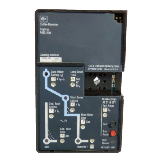
, Trip Unit - Operational Status Protection "Blinking Green"=OK . ��� � eRa t i � t, � "'"'· Desired Adjust Protection Settings Values Fig. 1 Digitrip RMS 510 T rip Unit Model LSIG with Rating Plug Effective May 1 997... - Page 43 I.L. 29-8858 Page 3 Fig. 2. 1 Long Time/Instantaneous Protection (LI) Fig. 2.3 Long Time/Short Time/Instantaneous Protection (LSI) Fig. 2.2 Long Time/Short Time Protection (LS) Fig. 2.4 Long Time/Instantaneous/Ground Protection (LIG) Effective May 1 997...
-
Page 44: Testing
Digitrip RMS 51 0 Trip Units are "Listed" by the U nderwrit The trip unit employs the Cutler-Hammer Inc. custom ers Laboratories, I nc. ® U nder UL File E78 1 9, for use in designed integrated circuit S).l.RE + chip, which includes a types DS, DSL, SPB and Series C ®... -
Page 45: Trip And Operation Indicators
{ lOAD, LOWE A I S)lRE+ Chip Fig. 3 Digitrip RMS 510 Block Diagram with Breaker Interface The microcomputer, in cyclic fashion, repeatedly scans 3.3 Test Provisions (See Section 5.0) the voltage values across each calibrating resistor and 3.4 DIScriminator (Making Current Release) enters these values into its Random Access Memory (RAM). -
Page 46: Override (Fixed Instantaneous)
I.L. 29-8858 Page 6 Note: If a breaker (M) receives a Zone Interlocking Notes: signal from another breaker (F), but the fault current This switch has eight (8) positions, and seven (7) level is less than the trip unit setting for breaker (M), of them show "DIS' in the window, while ONLY the signal from the other breaker (F) will not cause O N E position shows "[BLANK]". -
Page 47: Long Delay Current Settings
Page 7 I . L. 29-8858 4.2 Long Delay Current Setting allow for the fact that the load circuit temperature is already higher than normal, due to the prior There are eight (8) available Long Delay Settings, as "t;' overload condition. Each time an overload condi illustrated in Fig. -
Page 48: Short Delay Current Settings
I. L. 29-8858 Page s other two settings are "M 1 " or "M2" times (In) . The val ues LOT will reset itself. You can of course, manually that "M 1 " and "M2" have depend upon the type of circuit clear the LOT (or any other trip indication) at any breaker, and are specified both on the rating plug label time, by pushing the "... -
Page 49: Ground Fault Time Delay Settings
I.L. 29-8858 Page 9 1 ..,. .. 1 TABLE 1 - G ROUND FAULT CURRENT SETTINGS Available Settings GROUND FAULT CURRENT SETTINGS (AMPERES)<D 2. 2.5. 3 , 4, '.J"" 5. 6, M,. M, ffi:J : --\ Setting lnst. ltip x l n Rating Plug 1 00 ®... -
Page 50: Test Procedure
I . L. 29-8858 Page 1 0 Available "Test Amps" Settings Breaker Trips At GT and GFT CD "GT" = Phase Current Test at Gxl n and TRIPS breake �J) Test Amps " 1 , 2, 3, 8 or 1 0" = Phase Gnd Fault Current Test - NO �... -
Page 51: When To Test
I.L. 29-8858 Page 1 1 1 0% of the 5.2 When To Test the current is not less than breaker frame (or current sensor) rating; be Tests can be conducted with the breaker in the "con sure the "GREEN" U n it Status LED (in the nected"... -
Page 52: Not Tripping The Breaker
I .L. 29-8858 Page 1 2 the APM it may appear as if the trip unit does not trip unit will not execute your instructions to Test itself, when the load current exceeds 50% of 1,.) respond until the current is well-above the set value, leading the tester to believe there is an error in the Place the ''Test Amps"... -
Page 53: Auxiliary Power Module
I.L. 29-8858 Page 1 3 obtained from t h e following companies u nder their type Note: The battery can be replaced at any time, even designation indicated: while the circuit breaker is in service, without affect ing the operation of the circuit breaker or its protec Company Model tion function. -
Page 54: Auxiliary Power Module
I.L. 29-8858 Page 1 4 rent value (or "Sensor Rated", if applica 7.0 AUXILIARY POWER MODULE ble), The Auxiliary Power Module or APM (Cat No. and 2) (Rated I) current value. "In " P RTAAPM), illustrated in Fig. 7, is an encapsulated power supply that requires a 1 20 Vac input at either 50 or This latter value, (In) is the basis for the trip unit current 60 Hz. -
Page 55: Type Spb Systems Pow-R Breakers
I . L. 29-8858 Page 1 5 ® 9.0 REFERENCES I . L. 29C7 1 4 Master Connection Diagram for Series R- Frame Circuit Breaker 9.1 Digitrip RMS Trip Assemblies APPENDIX A ZONE INTERLOCKING I.L. 29-885 Instructions for Digitrip RMS 51 0 Trip Unit Assume a ground fault of 2000 Amperes occurs and I.L. -
Page 56: Protection
I .L. 29-8858 Page 1 6 Notes: A1 : Wiring to be twisted pair of AWG No. 1 4 to AWG No. 20. Route Zone Interlocking wiring sepa rate from power conductors. Main 3200 A DO NOT GROUND any Zone Interlock Wiring. - Page 57 I.L. 29-8858 Page 1 7 NOTES Effective May 1 997...
- Page 58 I.L. 29-8858 Page 1 8 NOTES Effective May 1 997...
- Page 59 I.L. 29-8858 Page 1 9 NOTES Effective May 1 997...
- Page 60 I NFORMATION, RECO M M ENDATIONS DESCRIPTIONS CONTAINED H EREIN. In no event will Cutler-Hammer Inc. be responsible to the purchaser or user in contract, in tort (including negligence), strict liability or otherwise for any special, indirect, incidental or consequential damage or loss whatsoever, including but...
-
Page 61: Type Ds Low Voltage Ac Power Circuit Breakers
Cutler-Hammer I . L. 29-8858 Instructions for Digitrip RMS 510 Tri p U n it Page Table of Contents WAR N I N G General Description ..... 1 Protection . -
Page 62: Protection
I.L. 29-8858 Page 2 The Digitrip RMS 51 0 Trip U nit is completely self-con Note*: RMS Digitrip Type Ll, LS, and LSI trip units tained and when the circuit breaker is closed, requires no can be applied on 3-pole or 4-pole circuit breakers for external control power to operate its protection sys... - Page 63 I.L. 29-8858 Page 3 Fig. 2. 1 Long Time/Instantaneous Protection (LI) Fig. 2. 3 Long Time/Short Time/Instantaneous Protection (LSI) Fig. 2.2 Long Time/Short Time Protection (LS) Fig. 2.4 Long Time/Instantaneous/Ground Protection (LIG) Effective May 1 997...
-
Page 64: Testing
Digitrip 51 0 Trip U n its are " Listed" by the U nderwrit The trip unit employs the Cutler-Hammer Inc. custom ers Laboratories, I nc. ® U nder UL File E78 1 9, for use in designed integrated circuit SJ.!HE + chip, which i ncludes a types DS, DSL, SPB and Series c ®... -
Page 65: Trip And Operation Indicators
S)..l R E+ Chip Resrstor Fig. 3 Digitrip RMS 510 Block Diagram with Breaker Interface The microcomputer, in cyclic fashion, repeatedly scans 3.3 Test Provisions (See Section 5.0) the voltage values across each calibrating resistor and enters these values into its Random Access Memory 3.4 DIScriminator (Making Current Release) -
Page 66: Override (Fixed Instantaneous)
I.L. 29-8858 Page S Note: If a breaker (M) receives a Zone Interlocking Notes: signal from another breaker (F), but the fault current This switch has eight (8) positions, and seven (7) level is less than the trip unit setting for breaker (M), of them show "DIS' in the window, while ONLY the signal from the other breaker (F) will not cause ONE position shows "[BLANK]". -
Page 68: Short Delay Current Settings
I.L. 29-8858 Page 8 other two settings are "M1 " or "M2" times (In). The values LOT will reset itself. You can of course, manually that "M 1 " and "M2" have depend upon the type of circuit clear the LOT (or any other trip indication) at any time, by pushing the "... -
Page 69: No Instantaneous Current Settings
I.L. 29-8858 Page 9 TABLE 1 - G ROUND FAULT CURRENT SETTINGS � X : _ - Ava i l a b l e Sett i n g s - _ - J GROUND FAULT CURRENT SETTI N G S (AMPERES)CD 2. -
Page 70: Ground Fault Time Delay Settings
I .L. 29-8858 Page 1 0 Available "Test Amps" Settings Breaker Trips CD "GT" = Phase Current Test at 6T and GFT n and TRIPS breaker; · Test Amps 8 or 1 0" = Phase " 1 , 2, 3, Fault NO 'b reaker Current Test... -
Page 71: When To Test
I.L. 29-8858 Page 1 1 1 0% of the 5.2 When To Test the current is not less than breaker frame (or current sensor) rating; be Tests can be conducted with the breaker in the "con sure the "GREEN" U n it Status LED (in the nected"... -
Page 72: Not Tripping The Breaker
I.L. 29-8858 Page 1 2 the A P M it may appear as i f the trip unit does not trip unit will not execute your instructions to Test respond until the current is well-above the set value, itself, when the load current exceeds 50% of leading the tester to believe there is an error in the Place the ''Test Amps"... - Page 73 I.L. 29-8858 Page 1 3 obtained from the following companies u nder their type Note: The battery can be replaced at any time, even designation indicated: while the circuit breaker is in service, without affect ing the operation of the circuit breaker or its protec Company Model tion function.
-
Page 74: Auxiliary Power Module
I.L. 29-8858 Page 1 4 rent value (or "Sensor Rated", if applica 7.0 AUXILIARY POWER MODULE ble) , The Auxiliary Power Module or APM (Cat No. and 2) ( Rated I) =" current value. "In P RTAAPM), illustrated in Fig. 7, is an encapsulated power supply that requ i res a 1 20 Vac input at either 50 or This latter value, (In) is the basis for the trip unit current 60 Hz. -
Page 75: References
I.L. 29-8858 Page ® 9.0 REFERENCES I . L. 29C71 4 Master Connection Diagram for Series R- Frame Circuit Breaker 9.1 Digitrip RMS Trip Assemblies APPENDIX A ZONE INTERLOCKING I.L. 29-885 Instructions for Digitrip RMS 51 0 Trip Unit Assume a ground fault of 2000 Amperes occurs and I. - Page 76 l.l. 29-8858 Page 1 6 Notes: A1 : Wiring to be twisted pair of AWG No. 1 4 to AWG No. 20. Route Zone Interlocking wiring sepa- rate from power conductors. M a i n 3200 A DO NOT GROUND any Zone Interlock Wiring.
- Page 77 I . L. 29-8858 Page 1 7 NOTES Effective May 1 997...
- Page 78 I . L . 29-8858 Page 1 8 NOTES Effective May 1 997...
- Page 79 I .L. 29-8858 Page 1 9 NOTES Effective May 1 997...
- Page 80 I N FORMATION, RECOMMENDATIONS DESCRIPTIONS CONTAINED HEREIN. In no event will Cutler-Hammer Inc. be responsible to the purchaser or user in contract, in tort (including negligence), strict liability or otherwise for any special, indirect, incidental or consequential damage or loss whatsoever, including but...
- Page 81 AND ALWAYS FOLLOW G E N ERALLY ACCEPTED DIScriminator (Making Current Release) ..5 SAFETY PROCEDURES. CUTLER-HAMMER IS NOT OVERRIDE (Fixed Instantaneous) ..6 LIABLE FOR THE MISAPPLICATION OR MISINSTAL...
-
Page 82: Protection
Curve lime-Current . Trip Unit Ground Operational Protection Status "Blinking Green''=OK with Rotary Switches Adjust Prot ection Settings Desired values Fig. 1 Digitrip RMS 510 T rip Unit Model LSIG with Rating Plug Effective May 1 997... - Page 83 I.L. 29-8858 Page 3 Fig. 2. 1 Long Time/Instantaneous Protection (LI) Fig. 2.3 Long Time/Short Time/Instantaneous Protection (LSI) Fig. 2.2 Long Time/Short Time Protection (LS) Fig. 2.4 Long Time/Instantaneous/Ground Protection (LIG) Effective May 1 997...
-
Page 84: Testing
Trip U n its are "Listed" the U nderwrit The trip unit employs the Cutler-Hammer Inc. custom ers Laboratories, I nc. ® U nder UL File E781 9, for use in designed integrated circuit S�R E + chip, which includes a types OS, DSL, SPB and Series c ®... -
Page 85: Trip And Operation Indicators
I.L. 29-8858 Page 5 r - - - - - - - - - - - - - - - - - - - - - - - - - - - - - - - - - - - - - - - - - - - - - - - - - - - - �... -
Page 86: Override (Fixed Instantaneous)
I.L. 29-8858 Page S Note: If a breaker (M) receives a Zone Interlocking Notes: signal from another breaker (F), but the fault current This switch has eight (8) positions, and seven (7) level is less than the trip unit setting for breaker (M), of them show "DIS"... -
Page 87: Long Delay Current Settings
I.L. 29-8858 Page 7 4.2 Long Delay Current Setting allow for the fact that the load circuit temperature is already higher than normal, due to the prior There are eight (8) available Long Delay Settings, as "/;' overload condition. Each time an overload condi illustrated in Fig. -
Page 88: Short Delay Current Settings
I . L. 29-8858 Page S other two settings are "M 1 " or "M2" times {In). The values LOT will reset itself. You can of course, manually that "M1 " and "M2" have depend upon the type of circuit clear the LOT (or any other trip indication) at any breaker, and are specified both on the rating plug label time, by pushing the "PUSH to RESET"... -
Page 89: No Instantaneous Current Settings
I.L. 29-8858 Page 9 r-, i"""l r-- TABLE 1 - GROUND FAULT CURRENT SETTINGS 1 l1 le Sett i n g GROUND FAULT CURRENT SETTINGS (AMPERES)<D 2. 2.5, 3, 4, 5, 6, M,, M, : -- \ 'J"" Setting lnst. u lt ples of x l n... -
Page 90: Ground Fault Time Delay Settings
I.L. 29-8858 Page 1 0 Available "Test Amps" Settings Breaker Trips CD "6T" = Phase Current Test at At 6T and GFT 6xl n and TRIPS breaker; GIJ1l 1 0" x I = Phase Test Amps " 1 , 2, 3, Fault NO �... -
Page 91: When To Test
(1 , 2, 3, 6T, 8 and 1 In) are available for testing the tection element, the Digitrip RMS 510 T rip Unit also phase elements of the trip u nit, and two (G F, GFT) are which has a Long Time Memory function (LTM), provided for testing the ground elements. -
Page 92: Not Tripping The Breaker
I.L. 29-8858 Page 1 2 the APM it may appear a s if the trip unit does not trip unit will not execute your instructions to Test itself, when the load current exceeds 50% of respond until the current is well-above the set value, leading the tester to believe there is an error in the Place the ''Test Amps"... - Page 93 I.L. 29-8858 Page 1 3 obtained from the following companies u nder their type Note: The battery can be replaced at any time, even designation indicated: while the circuit breaker is in service, without affect ing the operation of the circuit breaker or its protec Company Model tion function.
-
Page 94: Auxiliary Power Module
I.L. 29-8858 Page 1 4 rent value (or "Sensor Rated", if applica 7.0 AUXILIARY POWER MODULE ble), The Auxiliary Power Module or APM (Cat No. and 2) (Rated I) =" cu rrent value. "'In P RTAAPM), illustrated in Fig. 7, is an encapsulated power supply that requires a 1 20 Vac input at either 50 or This latter value, (In) is the basis for the trip unit current 60 Hz. -
Page 95: References
I.L. 29-8858 Page 1 5 ® 9.0 REFERENCES I . L. 29C714 Master Connection Diagram for Series R-Frame Circuit Breaker 9.1 Digitrip RMS Trip Assemblies APPENDIX A ZONE INTERLOCKING I.L. 29-885 I nstructions for Digitrip RMS 51 0 Trip Unit Assume a ground fault of 2000 Amperes occurs and I . - Page 96 I. L. 29-8858 Page Notes: A1 : Wiring to be twisted pair of AWG No. 1 4 to AWG No. 20. Route Zone Interlocking wiring sepa rate from power conductors. M a i n 3200 A DO NOT GROUN D any Zone Interlock Wiring.
- Page 97 I.L. 29-8858 Page 1 7 N OTES Effective May 1 997...
- Page 98 I.L. 29-8858 Page 1 8 N OTES Effective May 1 997...
- Page 99 I. L. 29-8858 Page 1 9 NOTES Effective May 1 997...
- Page 100 I N FORMATION, RECOMMENDATIONS DESCRIPTIONS CONTAINED HEREIN. In no event will Cutler-Hammer Inc. be responsible to the purchaser or user in contract, in tort (including negligence), strict liability or otherwise for any special, indirect, incidental or consequential damage or loss whatsoever, including but...
- Page 101 Cutler-Hammer I.L. 29-8858 I nstructions for Digitrip RMS 510 Trip U n it Page Table of Contents WARN I N G 1 .0 General Description ..... 1 1 .
-
Page 102: Protection
Phase Protection for Ground " Trip Unit Operational Status Protection "Blinking Green''=O K Adjust Protection Settings for Desired Values With Rotary Switches Fig. 1 Digitrip RMS 510 T rip Unit Model LSIG with Rating Plug Effective May 1 997... - Page 103 I.L. 29-8858 Page 3 Fig. 2. 1 Long Time/Instantaneous Protection (LI) Fig. 2.3 Long Time/Short Time/Instantaneous Protection (LSI) Fig. 2.2 Long Time/Short Time Protection (LS) Fig. 2. 4 Long Time/Instantaneous/Ground Protection (LIG) Effective May 1 997...
-
Page 104: Testing
Digitrip RMS 5 1 0 Trip U n its are "Listed" by the U nderwrit The trip unit employs the Cutler-Hammer Inc. custom ers Laboratories, I nc. ® U nder UL File E78 1 9, for use in designed integrated circuit S11RE + chip, which includes a types DS, DSL, SPB and Series (;®... -
Page 105: Trip And Operation Indicators
I. L. 29-8858 Page S FP��c�;������on11 r--------------------------------- ------------------- � �"v" S !:.; , � �:���':, rl Flu� Transle< Shun! Troo iFTS T I ,t ,t ,t " � )-- - - - - - .J See Secto o n 4 :��·... -
Page 106: Override (Fixed Instantaneous)
I . L. 29-8858 Page Notes: Note: If a breaker (M) receives a Zone Interlocking signal from another breaker (F), but the fault current This switch has eight (8) positions, and seven (7) level is less than the trip unit setting for breaker (M), of them show "... -
Page 107: Long Delay Current Settings
I.L. 29-8858 Page 7 4.2 Long Delay Current Setting allow for the fact that the load circuit temperature is already higher than normal, due to the prior There are eight (8} available Long Delay Settings, as overload condition. Each time an overload condi illustrated in Fig. -
Page 108: Short Delay Current Settings
I.L. 29-8858 Page B other two settings are "M1 " or "M2" times (In). The values LOT will reset itself. You can of course, manually that "M1 " and "M2" have depend upon the type of circuit clear the LOT (or any other trip indication) at any breaker, and are specified both on the rating plug label time, by pushing the "PUSH to RESET"... -
Page 109: Instantaneous Current Settings
I.L. 29-8858 Page 9 r-, 1 "" " 1 I'" TABLE - GROUND FAULT CUR RENT SETTINGS Ava ilable Settings 3, 4, GROUND FAULT CURRENT SETTI NGS (AMPERES)<D 2 . 2.5, "" 5, 6, M , , M, : -- \ Setting lnsL I n Multiples of x l n... -
Page 110: Test Procedu
I.L. 29-8858 Page 1 0 Available "Test Amps" Settings Breaker Trips 6T and GFT "6T' = Phase Current Test at 6xl n and TRIPS breaker; Test Amps "1 , 2, 3, 8 or 1 0" x l = Phase Gnd Fault Current Test ·... -
Page 111: When To Test
I.L. 29-8858 Page 1 1 1 0% of the 5.2 When To Test the current is not less than breaker frame (or current sensor) rating; be Tests can be conducted with the breaker in the "con sure the "GREEN" Unit Status LED (in the nected"... -
Page 112: Not Tripping The Breaker
I.L. 29-8858 Page 1 2 the APM it may appear as if the trip unit does not trip unit will not execute your instructions to Test respond until the current is well-above the set value, itself, when the load current exceeds 50% of 1,.) leading the tester to believe there is an error in the Place the ''Test Amps"... - Page 113 I. L. 29-8858 Page 1 3 obtained from the following companies u nder their type Note: The battery can be replaced at any time, even designation indicated: while the circuit breaker is in service, without affect ing the operation of the circuit breaker or its protec Company Model tion function.
-
Page 114: Auxiliary Power Module
I . L. 29-8858 Page 1 4 rent value (or "Sensor Rated", if applica 7.0 AUXILIARY POWER MODULE ble), The Auxiliary Power Module or APM (Cat No. and 2) (Rated I) =" current value. "In PRTAAPM), illustrated in Fig. 7, is an encapsulated power supply that requires a 1 20 Vac input at either 50 or This latter val ue, (In) is the basis for the trip u n it current 60 Hz. -
Page 115: References
I.L. 29-8858 Page 1 5 c ® 9.0 REFERENCES I.L. 29C7 1 4 Master Connection Diagram for Series A-Frame Circuit Breaker 9.1 Digitrip RMS Trip Assemblies I.L. 29-885 Instructions for Digitrip AMS 5 1 0 Trip Unit APPENDIX A ZONE INTERLOCKING Assume a ground fau lt of 2000 Amperes occurs and I.L. - Page 116 I.L. 29-8858 Page 1 6 Notes: A 1 : Wiring to be twisted pair of AWG No. 1 4 to AWG No. 20. Route Zone Interlocking wiring sepa- rate from power conductors. M a i n 3200 A DO NOT GROUND any Zone Interlock Wiring.
- Page 117 I.L. 29-8858 Page 1 7 NOTES Effective May 1 997...
- Page 118 I . L. 29-8858 Page 1 8 NOTES Effective May 1 997...
- Page 119 I.L. 29-8858 Page 1 9 N OTES Effective May 1 997...
- Page 120 I N FORMATION, RECOMMENDATIONS DESCRIPTIONS CONTA I N E D H EREIN. In no event will Cutler-Hammer I nc. be responsible to the purchaser or user in contract, in tort (including negligence), strict liability or otherwise for any special, indirect, incidental or...
- Page 121 Cutler-Hammer I . L. 29-8858 I nstructions for Digitrip RMS 510 Trip U n it Page Table of Contents WAR N I NG 1 .0 General Description ..... 1 1 .
-
Page 122: Protection
Status Ground Operational Protection View "Blinki n g Green"=OK Settings in Wi n dow with Adjust Protection Settings for Desired values Rotary Switches Fig. 1 Digitrip RMS 510 T rip Unit Model LSIG with Rating Plug Effective May 1 997... - Page 123 I . L. 29-8858 Page 3 Fig. 2. 1 Long Time/Instantaneous Protection (L/) Fig. 2. 3 Long Time/Short Time/Instantaneous Protection (LSI) Fig. 2.2 Long Time/Short Time Protection (LS) Fig. 2.4 Long Time/Instantaneous/Ground Protection (LIG) Effective May 1 997...
-
Page 124: Testing
Trip Units are "Listed" by the U nderwrit 5 1 0 The trip u nit employs the Cutler-Hammer Inc. custom ers Laboratories, Inc. ® U nder UL File E781 9, for use i n designed integrated circuit SJ..1.R E + chip, which includes a types DS, DSL, S P B and Series c ®... -
Page 125: Trip And Operation Indicators
Integrated Cir c uit \ LOAD, LOWER 1 S�J.RE+ Chip Digitrip RMS 510 Block Diagram with Breaker Interface Fig. 3 The microcomputer, in cyclic fashion, repeatedly scans 3.3 Test Provisions (See Section 5.0) the voltage values across each calibrating resistor and enters these values into its Random Access Memory 3.4 DIScriminator (Making Current Release) -
Page 126: Override (Fixed Instantaneous)
I . L. 29-8858 Page Note: If a breaker (M) receives a Zone Interlocking Notes: signal from another breaker (F), but the fault current This switch has eight (8) positions, and seven (7) level is less than the trip unit setting for breaker (M), of them show "... -
Page 127: Long Delay Current Settings
I.L. 29-8858 Page ? 4.2 Long Delay Current Setting allow for the fact that the load circuit temperature is already higher than normal, due to the prior There are eight (8) available Long Delay Settings, as "/;' overload condition. Each time an overload condi illustrated in Fig. -
Page 128: Short Delay Current Settings
J.L. 29-8858 Page 8 other two settings are "M1 " or "M2" times (In)- The values LOT will reset itself. You can of course, manually that "M 1 " and "M2" have depend upon the type of circuit clear the LOT (or any other trip indication) at any breaker, and are specified both on the rating plug label time, by pushing the "... - Page 129 I.L. 29-8858 Page 9 TABLE 1 - G ROU N D FAULT CUR R ENT SETIINGS � X - _ -1 Ava ilable Sett i n g s G ROUND FAULT CURRENT SETTI NGS (AMPERES)G:l 2, 2 . 5 , 3 , 4 , 5, 6, M , , M, Setting lnst.
-
Page 130: Ground Fault Time Delay Settings
I .L. 29-8858 Page 1 0 Available "Test Amps" Settings Breaker Trips " 1 , and G FT = Phase Current Test at " " 6xln �:!) TRIPS breaker; Test Amps 2, 3, r 1 0" x I = Phase Current Test - NO 'b reaker x In TRIP;... -
Page 131: When To Test
(1 , 2, 3, 6T, 8 and 1 OX In) are available for testing the tection element, the Digitrip RMS 510 T rip Unit also p hase elements of the trip u nit, and two (GF, G FT) are... -
Page 132: Not Tripping The Breaker
I.L. 29-8858 Page 1 2 the A P M i t may appear a s i f the trip unit does not trip unit will not execute your instructions to Test respond until the current is well-above the set value, itself, when the load current exceeds 50% of leading the tester to believe there is an error in the Place the 'Test Amps"... - Page 133 I.L. 29-8858 Page 1 3 obtained from the following companies u nder their type Note: The battery can be replaced at any time, even designation indicated: while the circuit breaker is in service, without affect ing the operation of the circuit breaker or its protec Company Model tion function.
-
Page 134: Auxiliary Power Module
I .L. 29-8858 Page 1 4 rent value (or "Sensor Rated", if applica 7.0 AUXILIARY POWER MODULE ble) , The Auxiliary Power Module or APM (Cat No. and 2) (Rated I) current value. "In " PRTAAPM), illustrated in Fig. 7, is an encapsulated power s upply that requires a 1 20 Vac input at either 50 or This latter val ue, (In) is the basis for the trip unit current 60 Hz. -
Page 135: References
I.L. 29-8858 Page 15 c ® 9.0 REFERENCES I . L. 29C7 1 4 Master Connection Diagram for Series R-Frame Circuit Breaker 9.1 Digitrip RMS Trip Assemblies I.L. 29-885 Instructions for Digitrip RMS 51 0 Trip Unit APPENDIX A ZON E INTERLOCKING Assume a ground fau lt of 2000 Amperes occurs and I.L. - Page 136 I.L. 29-8858 Page Notes: A1 : Wiring to be twisted pair of AWG No. 1 4 to AWG No. 20. Route Zone Interlocking wiring sepa rate from power conductors. M a i n 3200 A DO NOT GROUND any Zone Interlock Wiring.
- Page 137 I.L. 29-8858 Page 1 7 NOTES Effective May 1 997...
- Page 138 I.L. 29-8858 Page 1 8 N OTES Effective May 1 997...
- Page 139 I.L. 29-8858 Page 1 9 N OTES Effective May 1 997...
- Page 140 I N FORMATION, RECOMMENDATIONS DESCRIPTIONS CONTAINED HEREIN. I n no event will Cutler-Hammer Inc. be responsible to the purchaser or user in contract, in tort (including negligence), strict liability or otherwise for any special, indirect, incidental or consequential damage or loss whatsoever, including but...
- Page 141 Cutler-Hammer I. L. 29-8858 I nstructions for Digitrip RMS 510 Trip U n it Page Table of Contents WAR N I N G 1 .0 General Description ..... 1 1 .
- Page 142 Long Time/Short Time/Instantaneous LSI* Section 6.). Long Time/Instantaneous/Ground Long Time/Short Time/Ground Note: The Digitrip RMS 510 provides all of its protec Long Time/Short Time/I nstantaneous/ LSIG tion functions regardless of the status of the battery. Ground The battery serves only to maintain the indication of the reason for automatic trip.
- Page 143 I.L. 29-8858 Page 3 Fig. 2. 1 Long Time/Instantaneous Protection (LI) Fig. 2.3 Long Time/Short Time/Instantaneous Protection (LSI) Fig. 2.2 Long Time/Short Time Protection (LS) Fig. 2.4 Long Time/Instantaneous/Ground Protection (LIG) Effective May 1 997...
- Page 144 Digitrip RMS 5 1 0 Trip U n its are " Listed " the U nderwrit The trip unit employs the Cutler-Hammer Inc. custom ers Laboratories, I nc. ® Under UL File E78 1 9, for use in designed integrated circuit S)lRE + chip, which includes a types DS, DSL, SPB and Series C ®...
- Page 145 Chip C�hl>raHon Aes•sto· Fig. 3 Digitrip RMS 510 Block Diagram with Breaker Interface The microcomputer, in cyclic fashion, repeatedly scans 3.3 Test Provisions (See Section 5.0) the voltage values across each calibrating resistor and enters these values into its Random Access Memory 3.4 DIScriminator (Making Current Release)
- Page 146 I . L. 29-8858 Page Notes: Note: If a breaker (M) receives a Zone Interlocking signal from another breaker (F), but the fault current This switch has eight (8) positions, and seven (7) level is less than the trip unit setting for breaker (M), of them show "DIS"...
- Page 147 I. L. 29-8858 Page 7 4.2 Long Delay Current Setting allow for the fact that the load circuit temperature is already higher than normal, due to the prior There are eight available Long Delay Settings, as ''1/' overload condition. Each time an overload condi illustrated in Fig.
- Page 148 I.L. 29-8858 Page B other two settings are "M 1 " or "M2" times (In) . The val ues LOT will reset itself. You can of course, manually that "M 1 " and "M2" have depend upon the type of circuit clear the LOT (or any other trip indication) at any breaker, and are specified both on the rating plug label time, by pushing the "PUSH to RESET"...
- Page 149 I.L. 29·8858 Page 9 TABLE - G ROUND FAULT CURRENT SETTINGS Ava ilable Settings 1"" 1 GROUND FAULT CURRENT SETTINGS (AM PERES)CD 2, 2.5, 3, 4, 5, 6, M , , M , Setting lnst. I n Multiples of 1 00 Rating P l u g ®...
- Page 150 I.L. 29-8858 Page 1 0 Available "Test Amps" Settings Breaker Trips "6T" = Phase Current Test at At 6T and GFT 6xl n and TRIPS breaker; [ill ' :D 8 or 1 0 " x I = Phase Test Amps "...
- Page 151 I .L. 29-8858 Page 1 1 5.2 When To Test the current is not less than 1 0% of the breaker frame (or cu rrent sensor) rating; be Tests can be conducted with the breaker in the "con s u re the "GREEN" Unit Status LED (in the nected"...
- Page 152 I . L. 29-8858 Page 1 2 the APM it may appear as if the trip unit does not trip unit will not execute your instructions to Test respond until the current is well-above the set value, itself, when the load current exceeds 50% of leading the tester to believe there is an error in the Place th e "Test Amps"...
- Page 153 I.L. 29-8858 Page 1 3 Note: The battery can be replaced at any time, even obtained from the following companies under their type while the circuit breaker is in service, without affect designation indicated: ing the operation of the circuit breaker or its protec Company Model tion function.
- Page 154 I.L. 29-8858 Page 1 4 7.0 AUXILIARY POWER MODULE rent value (or "Sensor Rated", if appl ica ble) , The Auxiliary Power Module or APM (Cat No. and 2) "In (Rated I) =" cu rrent value. PRTAAPM), illustrated in Fig. 7, is an encapsu lated power supply that requi res a 1 20 Vac input at either 50 or This latter value, (In) is the basis for the trip unit current 60 Hz.
- Page 155 l .L. 29-8858 Page 1 5 c ® 9.0 REFERENCES I. L. 29C7 1 4 Master Connection Diagram for Series R-Frame Circuit Breaker 9.1 Digitrip RMS Trip Assemblies APPENDIX A ZONE INTERLOCKING I.L. 29-885 I nstructions for Digitrip RMS 51 0 Trip U nit Assume a ground fault of 2000 Amperes occu rs and I.L.
- Page 156 I . L. 29-8858 Page 1 6 Notes: A1 : Wiring to be twisted pair of AWG No. 14 to AWG No. 20. Route Zone I nterlocking wiring sepa rate from power conductors. 3200 A Ma i n DO NOT GROU N D any Zone Interlock Wiring.
- Page 157 I.L. 29-8858 Page 1 7 N OTES Effective May 1 997...
- Page 158 I . L. 29-8858 Page 1 8 N OTES Effective May 1 997...
- Page 159 I.L. 29-8858 Page 1 9 NOTES Effective May 1 997...
- Page 160 A N D DESCRIPTIONS CONTAINED H E R E I N . I n no event will Cutler-Hammer Inc. be responsible to the p urchaser or user in contract, in tort (including negligence), strict liability or otherwise for any special , indirect, incidental o r...
- Page 161 Test Provisions ......5 SAFETY PROCEDURES. CUTLER-HAMMER IS NOT DIScriminator (Making Current Release) ..5 OVERRIDE (Fixed Instantaneous) .
-
Page 162: Protection
2 . 3 Long Time/Instantaneous/Ground 2 . 4 Section 6.). Long Time/Short Time/G round Note: The Digitrip RMS 510 provides all of its protec Long Time/Short Time/I nstantaneous/ LSIG tion functions regardless of the status of the battery. Ground The battery serves only to maintain the indication of the reason for automatic trip. - Page 163 I.L. 29-8858 Page 3 Fig. 2. 1 Long Time/Instantaneous Protection (LI) Fig. 2.3 Long Time/Short Time/Instantaneous Protection (LSI) Fig. 2.2 Long Time/Short Time Protection (LS) Fig. 2.4 Long Time/Instantaneous/Ground Protection (LIG) Effective May 1 997...
-
Page 164: Testing
Tri p U n its are " Listed " by the U nderwrit 51 0 The trip unit employs the Cutler-Hammer Inc. custom ers Laboratories, I nc. ® U nder U L File E781 9, for use in designed integrated circuit S)lRE + chip, which includes a types OS, DSL, S P B and Series c ®... -
Page 165: Trip And Operation Indicators
! LOAD LOWER I Sf.lRE+ Chip Fig. Digitrip RMS 510 Block Diagram with Breaker Interface The microcomputer, in cyclic fashion, repeatedly scans 3.3 Test Provisions (See Section 5.0) the voltage values across each cal ibrating resistor and 3.4 DIScriminator (Making Current Release) enters these values into its Random Access Memory (RAM). -
Page 166: Override (Fixed Instantaneous)
I.L. 29-8858 Page Note: If a breaker (M) receives a Zone Interlocking Notes: signal from another breaker (F), but the fault current This switch has eight (8) positions, and seven (7) level is less than the trip unit setting for breaker (M), of them show "... -
Page 167: Long Delay Current Settings
I.L. 29-8858 Page ? 4.2 Long Delay Current Setting allow for the fact that the load circuit temperature is already higher than normal, due to the prior ''!;' There are eight (8) available Long De lay Settings, as overload condition. Each time an overload condi ill ustrated in Fig. -
Page 168: Short Delay Current Settings
I.L. 29-8858 Page 8 LOT will reset itself. You can of course, manually other two settings are "M 1 " or "M2" times (In)· T he values clear the LOT (or any other trip indication) at any that "M 1 " and "M2" have depend u pon the type of circuit time, by pushing the "PUSH to RESET"... -
Page 169: Ground Fault Current Settings
I.L. 29-8858 Page 9 - - \ TABLE 1 - GROUND FAULT CURRENT SETTINGS Available Sett i n g s .,-I GROUND FAULT CURRENT SETTINGS (AMPERES)CD 2. 2.5. 3. 4. 5. 6, M , . M 2 � m ' ' " Setting lnst. -
Page 171: When To Test
I.L. 29-8858 Page 1 1 5.2 When To Test the current is not less than 1 0% of the breaker frame (or current sensor) rating; be Tests can be conducted with the breaker in the "con sure the "G R EEN" U nit Status LED (in the nected"... -
Page 172: Battery (Inside The Rating Plug)
I.L. 29-8858 Page 1 2 the APM it may appear as if the trip unit does not trip unit will not execute your instructions to Test itself, when the load current exceeds 50% of respond until the current is well-above the set value, leading the tester to believe there is an error in the Place the 'Test Amps"... - Page 173 I. L. 29-8858 Page 1 3 Note: The battery can be replaced at any time, even obtained from the following companies u nder their type while the circuit breaker is in service, without affect designation indicated: ing the operation of the circuit breaker or its protec Company Model tion function.
-
Page 174: Auxiliary Power Module
I.L. 29-8858 Page 1 4 7.0 AUXILIARY POWER MODULE rent val ue (or "Sensor Rated", if appl ica ble), The Auxiliary Power Mod ule or APM (Cat No. and 2) "In (Rated I) =" cu rrent value. PRTAAPM), illustrated in Fig. 7, is an encapsulated power supply that requires a 1 20 Vac input at either 50 or This latter value, (In) is the basis for the trip unit current 60 Hz. -
Page 175: References
I.L. 29-8858 Page 1 5 c ® 9.0 R EFERENCES I . L. 29C7 1 4 Master Connection Diagram for Series R-Frame Circuit Breaker 9.1 Digitrip RMS Trip Assemblies APPENDIX A ZONE INTERLOCKING I . L. 29-885 Instructions for Digitrip RMS 51 0 Trip Unit Assume a ground fault of 2000 Amperes occurs and I . - Page 176 I .L . 29-8858 Page 1 6 Notes: A1 : Wiring to be twisted pair of AWG No. 1 4 to AWG No. 20. Route Zone Interlocking wiring sepa rate from power conductors. M a in 3200 A DO NOT GROUND any Zone Interlock Wiring.
- Page 177 I.L. 29-8858 Page 1 7 N OTES Effective May 1 997...
- Page 178 I . L . 29-8858 Page 1 8 N OTES Effective May 1 997...
- Page 179 I. L. 29-8858 Page 1 9 NOTES Effective May 1 997...
- Page 180 Cutler-Hammer. Sale of product shown in this literature is subject to terms and conditions outli ned in appropriate Cutler-Hammer I nc. selling policies or other contractual agreement between the parties. This literature is not intended to and does not enlarge or add to any such .
Need help?
Do you have a question about the Digitrip RMS 510 and is the answer not in the manual?
Questions and answers