
Related Manuals for SenTech IR-SNIF-MCD Series


Summary of Contents for SenTech IR-SNIF-MCD Series
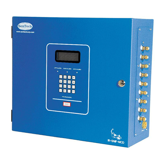
- Page 1 INSTALLATION AND OPERATION MANUAL ENVIRONMENTAL SYSTEM IR-SNIF-MCD MODELS MCD-1, 4, 8 & 16 SenTech Corporation 5745 Progress Road Indianapolis, Indiana 46241 888/248-1988 FAX 317/248-2014...
- Page 2 If your monitor has a version that is older (smaller version number such as 2143), a version specific appendix A, Programming and Operator Interface, is available. It can be downloaded from the SenTech Corporation website, www.sentechcorp.com, or directly from SenTech Corporation at 888-248-1988.
-
Page 3: Table Of Contents
APPENDIX A: Programming and Operator Interface.............. 30 Summary ..........................30 Start-up Screens ........................30 Operational Screens ......................30 Menu Screens........................32 APPENDIX B: SenTech Room Volume Considerations ............40 APPENDIX C: Parts List and Wire List................... 44 TROUBLESHOOTING GUIDE ....................47 SenTech Manufacturer's Limited Warranty................50... -
Page 4: Safety Precautions And Warnings
Failure to comply with these precautions, given here and elsewhere in the manual violates safety standards of design, manufacture, and intended use. SenTech Corporation assumes no liability for the customer’s failure to comply with these requirements. Definitions of safety symbols used on equipment and in manuals. -
Page 5: Models Mcd-1, 4, 8 & 16 Specifications
Models MCD-1, 4, 8 & 16 Specifications Size: 16.5” x 15” x 6.75” (42cm x 38.1cm x 17cm) Weight: Model MCD-1 - 30.4 lbs. (13.8 kg) Model MCD-4 - 31.4 lbs. (14.2 kg) Model MCD-8 - 33.8 lbs. (15.3 kg) Model MCD-16 - 36.0 lbs. -
Page 6: Introduction And Overview
Should the system assess the presence of refrigerant as a leak, using SenTech’s “LEAK WAIT” algorithm, the user is notified. By discovering a leak shortly after it starts, the potential loss can be reduced to ounces of refrigerant, saving money and helping protect the environment. - Page 7 Pneumatics: Refer to the figure 2 for pneumatics block diagram. Tubing from the areas to be monitored and from a reference air source (either fresh, outside air, or interior conditioned air that is free of refrigerants) is connected to the valve manifold. The MCD1 has a single sample valve and a reference valve, for a total of two valves.
- Page 8 Infrared Bench: Refer to the figure 3 for Infrared Bench diagram. The infrared bench has an integrated source circuit with infrared source at one end and an integrated detector circuit with filter and detector at the other. Presence of refrigerant in the sample air will cause a change in the output of the detector.
- Page 9 Control Electronics: Refer to the figure 4 for control electronics block diagram. The signal from the infrared bench is analyzed by the control circuit and converted into a digital measurement in ppm (parts per million). The ppm level is compared to trip points set for Low, Main and High alarm levels.
- Page 10 Power Supply: Refer to the figure 5 for Power Supply diagram. Power is supplied to the monitor through terminals 1, 2 and 3 of the terminal board. Line voltage is fed through the fuse on the left side of the monitor (not shown), and to the diaphragm pump and power supply. The power supply converts AC line voltage to dc voltage.
-
Page 11: Sensitivity To Refrigerants
ratio eliminates the effect of any variations, Sensitivity to Refrigerants and eliminates the need to periodically calibrate a monitor in the field. The system is sensitive in varying amounts to all of the halogen-based refrigerants, PPM vs. Leak Rate those containing molecules of fluorine, chlorine or both. -
Page 12: System Block Diagram
SYSTEM Block Diagram To Computer (rs-232) Valves To Phone Line (cat-3) (rs-232) Area 3 Area 4 Area 5 (rs-485) Area 6 Analog To BMS Area 7 (0-10 vdc or optional 4-20mA) Area 8 Binary To BMS (dry contacts) Binary To BMS Exhaust (optional individual alarm relays - control voltage only) Item... - Page 13 Alarm Connections: ACC 020 Combination Horn/Strobe Alarm Optional - Purchased separately from monitor, Install in 120 vac alarm, surface mounted using mechanical room so that it can be seen and heard from all included 4x4 box, or flush mounted areas, control Strobe portion with LOW alarm relay, using customer provided 4x4 box control Horn portion with HORN relay installed in finished wall, horn and...
- Page 14 Remote Digital Interface Connections: ACC 065 Remote Control Panel Interface, full Optional – Purchased separately from monitor, provides function remote control for monitor complete remote interface for all monitors in building via rs-485 interface (subject to cable length limitations of rs- 485), powered by 24 vac transformer Field Wiring 14 or 16 AWG (Line voltage supply to...
-
Page 15: Installation
5 amps no exhaust tube is required. 4. ¼ inch tubing (if not purchased from SenTech, or if copper tube is Caution: Liquid can affect the required by local code) performance of the monitor. -
Page 16: Electrical Power Connection
the air, the pick up point should be mounted partially obstruct the tube end filter where it is most likely to sense leaking and change the reference signal. refrigerant. The criteria to consider in 5. If located outdoors, the tube end selecting the sample pick up point location filters must not be located near include:... -
Page 17: Electrical Alarm Connections
240 vac. Refer to figure 6 for a diagram of of NO/NC dry contacts. Refer to figure 7 for the TB1 terminal board. a diagram of the relay socket. Caution: Verify that the monitor is designed for the appropriate line voltage. -
Page 18: Other External Connections
Caution: Ensure that external external reset input and optional rs-485 relay connections do not touch interface for use with ACC 070 SenTech relay control terminals 13 and 14. COMM LINK PC to Refrigerant Monitor A short circuit from the exhaust... - Page 19 This signal should NOT be used RS-485 interface for use with ACC 070 as a replacement for discrete alarm relay SenTech COMM LINK PC to Refrigerant connections to a BMS. Analog output Monitor Interface, or ACC 065 SenTech connections are as follows: Remote Control Panel Interface.
- Page 20 TB3 on the capability to provide additional discrete the back-plate. Secure the twisted control signals. Please contact SenTech wire periodically to the wire harness Corporation technical support to determine using tie wraps. whether specific requirements can be 3.
-
Page 21: Startup And Programming
STARTUP and PROGRAMMING Apply Power SenTech Corporation IR-SNIF-MCD16 Caution: Before applying power, Gas Monitor double-check all wiring. Copyright (c) 2004 Once the installation has been completed, The monitor will next display two Contact and wiring has been checked, close the and Model Information screens. -
Page 22: Normal Operation
The first four passwords can be changed to user-defined codes. ** Auto Zero** 999 cannot be changed. Timer 24 12:00 * SenTech Monitor * Press ENT for Menu ENTER PASSWORD Followed By ENT The Auto Sample measurement will be Code :... - Page 23 When the correct password has been The autozero flag can be used to limit the entered the monitor will display the setup frequency of autozero cycles. It can be set screen. between 0 and 100. If a 0 is entered, the monitor will enter an autozero cycle after every area is sampled (this is the normal 1)…IR Setup...
- Page 24 The unit number flag is used to identify the analog output. The factory default is 1000, monitor on a RS-485 network, if that option meaning that the 0-10 volt analog output has been purchased. This flag is set to 1 corresponds to 0-1000 ppm.
- Page 25 If there are any questions regarding the Day (0-31): 27 correct implementation of this feature, call Year (00-99): 04 SenTech technical support. Press the “ENT” key to move the cursor to When the date and time have been the next entry. When all entries have been entered, press the “ENT”...
- Page 26 25 - Alarm Main Alarm High Press the “1” key to setup parameters for ENT or ABORT each area. Unless specified otherwise, SenTech AREA <- -> Corporation recommends following R-134A alarm settings for all refrigerants except R- Distance 250 123:...
- Page 27 the short-term exposure level. These are Press the left or right arrow keys to change recommended settings only. Refer to local from one sample area screen to another. codes and regulations for the appropriate Press the “ENT” key to move the arrow settings for a given application.
-
Page 28: Final Tests
If there is no leak and 1)…Low 2)…Main there are no other sources of halogen 3)…HIGH 4)…All vapors in the room, contact SenTech RESET To Clear technical support. With the alarm relays energized, confirm Integration with External Devices that the monitor is correctly integrated into the building systems. -
Page 29: Response To Refrigerant
Because this, bag or even an open top jar or can. The SenTech Corporation recommends use of container should be at least 4 liters, or an HFC, such as R134A for field-testing of about a gallon. The container should be the IR-SNIF series of monitors. -
Page 30: End-To-End System Test
b) Liquid Refrigerants: Open the container highest alarm level. This will be used to slightly and put in a few drops of liquid test the end-to-end performance of the refrigerant. Loosely close the container and system in the next step. allow time for the refrigerant to gasify. -
Page 31: Documentation
If you need any additional manuals, call "RESET to Clr Alarms". This instructs the SenTech and we will be pleased to provide operator to clear the alarms. them at no charge (make a note of the unit serial number when requesting a manual). -
Page 32: Preventive Maintenance & Repair
Additionally, SenTech Corporation provides 5 Micron Filter is located inside the telephone technical support for all SenTech monitor, inside a clear moisture separator. refrigerant monitors. If assistance is The 5 micron filter should be ‘paper white’,... -
Page 33: Appendix A: Programming And Operator Interface
Auto sample to Auto initialization. zero, and back to Auto sample. If an alarm condition is detected the monitor will enter SenTech Corporation Leak Wait mode to ensure a leak is IR-SNIF-MCD16 detected. operator manually... - Page 34 monitor time outs and returns to normal point, the system will determine that it was operation. a transient, and return to normal operation. Auto zero: Auto zero measures the fresh LEAK WAIT AREA 1 air (refrigerant free) zone between each 12:00 zone.
-
Page 35: Menu Screens
operational screens will change to instruct Status: The Status Screen is accessed by the operator how to silence the Horn. pressing the "1" key. The status screen will When the alarm condition is cleared, the allow the operator to review alarms and to Horn is enabled and will be activated review trend data, if trending is enabled on should another alarm occur. - Page 36 trending screen will display two lines of Trouble Alarm information that is twenty lines long, and up Bench Voltage to 120 columns wide. This feature is best Call Factory used in conjunction with the ACC 070 <- RESET or ABORT -> Comm Link and a windows based PC to view and track trend information.
- Page 37 The last Distance 250 password is permanently set at "999". ENT or ABORT * SenTech Monitor * Press the left or right arrow keys to change ENTER PASSWORD from one sample area to another. Press Followed By ENT the “ENT” key to move the arrow cursor Code : from line one to line two.
- Page 38 410A-AZ20, R-500, R-502, R-503, R-507- average refrigerants. SenTech AZ50 recommends that under no circumstances This list changes over time, so it is should a refrigerant monitor be set above recommended that the operator review the the short-term exposure level. These are Gas Code screens for a complete list of recommended settings only.
- Page 39 System Flags while the monitor is still in alarm. This Press the “2” to enter the System Flags feature useful when user screens. The system flag screen will troubleshooting an alarm, and wants to display information five settings, work in silence. Set the horn relay flag to 1 displayed on two screens.
- Page 40 If there are any questions regarding the correct implementation of this feature, call Press the “ENT” key to move the cursor to SenTech technical support. the next entry. When all entries have been viewed, press the “ENT” key again to Press the “ENT”...
- Page 41 Note that the RTC operates on a 24-hour Alarm Test clock. For example to enter 2 PM, enter the 1)…Low 2)…Main hour as 14, rather than 2. 3)…HIGH 4)…All Press Key To Test Program Time/Date Month (1-12): 10 Key selections 1, 2, and 3 are used to Day (0-31): 27 energize the Low, Main and High alarm Year (00-99): 04...
- Page 42 For Weekly trend rate, the monitor will Hour (0-23) request: Minute (0-59) Day of week (0-6) Hour (0-23) For Hourly trend rate, the monitor will Minute (0-59) request: Minute (0-59) For Daily trend rate, the monitor will request:...
-
Page 43: Appendix B: Sentech Room Volume Considerations
APPENDIX B: SenTech Room Volume Considerations (English) Normal industry practice has been to think concentration than calculated from the ideal about refrigerant leaks in terms of pounds formulas. of refrigerant per unit time, such as lbs/hr or oz/yr. This is a natural and logical way of Formula Definitions: looking at it. - Page 44 Two examples have been developed to demonstrate the conversion. Case I is for a sealed room, with no air turnover. Case II is for a room with a known air turnover. Given air turnover of 100cfm, calculate the Case I: Sealed room 40 ft x 30 ft x 10 ft fresh air volume in cuft/hr: Air flow (cuft/hr) = air flow (cfm) x [60(min)/1(hr)] high...
- Page 45 SenTech Room Volume Considerations (Metric) Normal industry practice has been to think concentration than calculated from the ideal about refrigerant leaks in terms of pounds formulas. of refrigerant per unit time, such as lbs/hr or oz/yr. This is a natural and logical way of Formula Definitions: looking at it.
- Page 46 Two examples have been developed to demonstrate the conversion. Case I is for a sealed room, with no air turnover. Case II is for a room with a known air turnover. Case I: Sealed room 15 m x 10 m x 3 m Given air turnover of 225cubic meter/hr, high calculate the leak rate that is required to...
-
Page 47: Appendix C: Parts List And Wire List
APPENDIX C: Parts List and Wire List Parts List: Refer to figure 6 for approximate location of the following parts: 421009, Door, IR-SNIF-MCD 13. 422031, Processor, Control 421014, Box, IR-SNIF-MCD 14. 421036, Display (not shown) 421016, Backplate, IR-SNIF-MCD 15. 421031, Keypad, IR-SNIF-MCD and IR-SNIF-1,2,3 (not 410144, Tube End Filter, (not shown) shown) 410357, Fitting, 1/8 Hose Barb, (not shown) - Page 48 Wire List: The following list defines every wire in the monitor. Abbreviations are defined as follows: P1 = Power Supply F1 = Fuse Holder TB1, TB2, TB3, TB4 = Terminal Board K1, K2, K3, K4 = Relays A1 = Control Board A2 = IR Bench A3 = Valve Driver Board A4 = Keypad...
- Page 49 A3-J4-15 Area 8 Gnd In 18 AWG, Black Part of Valve Assembly A3-J4-16 Area 8 Power In 18 AWG, Black Part of Valve Assembly A3-J4-17 Ref Air Gnd In 18 AWG, Black Part of Valve Assembly A3-J4-18 Ref Air Power In 18 AWG, Black Part of Valve Assembly K1-14...
-
Page 50: Troubleshooting Guide
All procedures in this can be performed with simple hand tools and a volt-ohm meter. If at any time, additional assistance is required, call SenTech Corporation at 888-248-1988 for technical support. 1. No Power a) Check the fuse and replace if failed. - Page 51 power fault in the control board, or a wiring short causing a power fault in the control board. Turn off the monitor and remove one connector at a time from the control board. Apply power between each step. If the dc voltages remain out of spec, the control board has failed.
- Page 52 If the monitor does not respond to refrigerant, contact SenTech Corporation technical support. 6. System Alarms when no a) Verify that the alarm is not a “Trouble Alarm” as Leak is Found described in Appendix A. b) Verify that the alarm settings are not set too low.
-
Page 53: Sentech Manufacturer's Limited Warranty
SenTech by SenTech, provided that notice of such defect is given by original purchaser- user to SenTech within one (1) year from the date of original installation (Warranty Registration Must Be On File) or 15 months from the date of sale of the equipment to the original purchaser whichever comes first. - Page 54 05/21/2008...
Need help?
Do you have a question about the IR-SNIF-MCD Series and is the answer not in the manual?
Questions and answers