Panasonic VL-SV74 Installation Manual
Video intercom system; main monitor station; door station.
Hide thumbs
Also See for VL-SV74:
- Operating instructions manual (32 pages) ,
- Quick start manual (2 pages) ,
- Manual (2 pages)
Advertisement
R This guide is for use with the above 3 models.
R The VL-SV74 models composition consists of VL-MV74 and VL-V524.
R The Installation Guide in Indonesian and Thai can be accessed from the following site:
https://panasonic.net/cns/pcc/support/intercom/sv74
R Door station is described as "doorphone" and Main monitor station is described as "main
monitor" in this guide.
R In this guide, the suffix of each model number (e.g., the "BX" in "VL-SV74BX") is omitted
unless necessary.
Note to the installer
R Before attempting to connect or operate this product, please read the label on the rear of
the doorphone and the main monitor/extension monitor.
R Please read this guide carefully, and install the product safely and correctly by following
the instructions. Carefully read the information found in the section titled "For your
safety" in particular.
R Only use attachments/accessories specified by the manufacturer.
R The installation shall be carried out in accordance with all applicable installation rules.
R To the maximum extent permitted by law, Panasonic assumes no responsibility for
injuries or property damage resulting from failures arising out of improper installation
or operation inconsistent with this document.
R After installation, make sure to leave this guide with the customer.
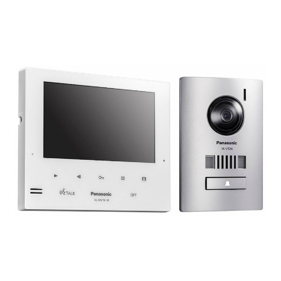
Model Name
Video Intercom System
Main Monitor Station
Door Station
VL-V524
Door station
Installation Guide
VL-MV74
Main monitor station
Model No.
Model No.
VL-SV74
VL-MV74
VL-V524
Advertisement
Table of Contents

Subscribe to Our Youtube Channel
Related Manuals for Panasonic VL-SV74


Summary of Contents for Panasonic VL-SV74
-
Page 1: Installation Guide
R Only use attachments/accessories specified by the manufacturer. R The installation shall be carried out in accordance with all applicable installation rules. R To the maximum extent permitted by law, Panasonic assumes no responsibility for injuries or property damage resulting from failures arising out of improper installation or operation inconsistent with this document. -
Page 2: For Your Safety
– Places where the main monitor/ For your safety extension monitor may be splashed with water or chemicals. To prevent severe injury or loss of life or – Places where there is a high property, and to ensure proper and safe concentration of dust, or high operation of your product, read this humidity. -
Page 3: Supplied Accessories For Installation
Supplied accessories for installation For the doorphone Screw × 4 (4 mm × 12 mm) Screw × 2 (3.8 mm × 20 mm) Mounting base × 1 Screw × 4 (4 mm × 25 mm) For the main monitor/extension monitor Screw ×... -
Page 4: Precautions For Installation
Precautions for installation To avoid malfunction or communication disturbances, do not install the doorphone or the main monitor/ extension monitor in the following locations: – Places where vibration or any other kind of impact occurs. – Places where echoing is frequent. –... -
Page 5: Wiring Schematic Diagram
Wiring schematic diagram Set up correctly according to the following wiring schematic diagram and "Wire type and length". R For information, such as order numbers, about optional devices that can be connected to, refer to the "Additional/replacement accessories" section in the Operating Instructions. DOORPHONE 1 DOORPHONE 2 MAIN MONITOR... - Page 6 Wire type and length Wire type Wiring run Diameter Length (Max.) ø 0.65 mm 22 AWG 100 m Doorphone – Main monitor – ø 1.0 mm 18 AWG 130 m Extension monitor ø 0.5 mm CAT 5 50 m According to the Main monitor –...
- Page 7 Connecting an optional lobby station For information about connections, refer to the documentation of the lobby station to be connected. Example: VL-V591 Lobby station MAIN MONITOR <Rear view> Ml-1 Ml-2 MO-1 MO-2 MO-3 MO-4 MO-5 MO-6 NP: Non-polarised <Be sure to perform the following to ensure proper operation> R Connecting an optional VL-V591 lobby station –...
-
Page 8: Doorphone Installation Position
Doorphone installation position Installation position of the doorphone and camera range Views when the camera is facing forwards at 0° (default). R Example: Installation height is 1450 mm (standard position). (Units: mm) A view when looking from above A Image range B Approx. 54° C Centre of doorphone D Approx. 1450 E Approx. 500 F Approx. -
Page 9: Installing The Doorphone
When using flush mount box (option): Installing the doorphone Model No. VL-MB524 Install the flush mount box (A) in the Important: wall. R On the bottom surface of the doorphone and the mounting base, there are holes to allow water to drain. - Page 10 Examples of camera angle Attach the doorphone to the mounting base. Facing forwards Facing upwards Facing left Facing upper left A Screws (accessory) × 4 When using flush mount box (option): Model No. VL-MB524 Attach the doorphone to the flush mount R The angle can also be adjusted to the right box.
- Page 11 Main monitor/extension Installing the main monitor/ monitor installation position extension monitor About the installation position of the main Attach the mounting bracket (A) to the wall monitor/extension monitor and mounting securely. bracket R Install the mounting bracket on a vertical flat R Place the main monitor/extension monitor in a wall (B).
- Page 12 Important: R Do not connect the power cable. (Damage may occur.) Note: R Do not remove the terminal cover. Mount the main monitor/extension monitor to the mounting bracket. 3-1 Line up the tab on the bottom of the bracket with the groove on the main monitor/ extension monitor.
- Page 13 Notes...
- Page 14 Notes...
- Page 15 Notes...
- Page 16 1006, Oaza Kadoma, Kadoma-shi, Osaka 571-8501, Japan http://www.panasonic.com © Panasonic Corporation 2019 PNQX8844ZA C0319MM0...
Need help?
Do you have a question about the VL-SV74 and is the answer not in the manual?
Questions and answers
Merhaba kurumu için bilgi alabilir miyim