Kaysun COMPAK KHP 35/300 ACS1 Technical Manual
Combo type heat pump water heater
Hide thumbs
Also See for COMPAK KHP 35/300 ACS1:
- Technical manual (52 pages) ,
- Owners & installation manual (23 pages) ,
- Installation & owner's manual (24 pages)

Related Manuals for Kaysun COMPAK KHP 35/300 ACS1


Summary of Contents for Kaysun COMPAK KHP 35/300 ACS1
- Page 1 Technical Manual Combo Type Heat Pump Water Heater COMPAK KHP 35/300 ACS1 Kaysun reserves the right to discontinue or change specification or designs at any time without notices and without incurring obligations.
-
Page 2: Table Of Contents
Technical Manual Content 1. GENERAL INFORMATION ..............3 1.1 Measurements ........................ 3 1.2 External appearance ....................... 3 2. COMBO TYPE HEAT PUMP WATER HEATER ........3 2.1 Features .......................... 3 2.2 Refrigerant circuit ......................5 2.3 Unit structure ........................7 2.4 Specifications ........................ -
Page 3: General Information
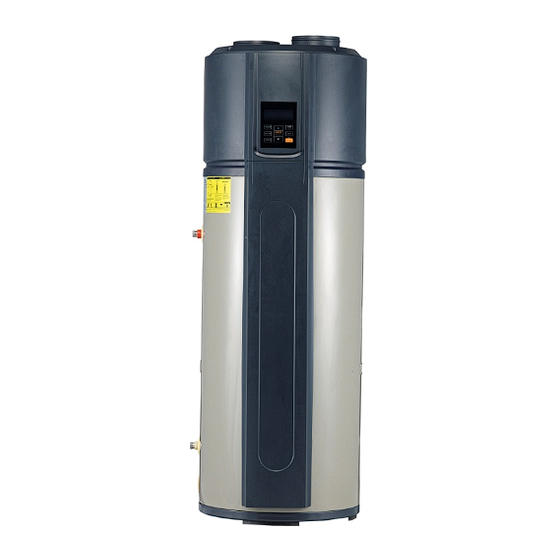
1. General Information 1.1 Measurements Model Net/Gross weight (kg) Dimension (mm, D×H) Power Supply COMPAK KHP 35/300 ACS1 145.5/175.5 Ф650×1920 220-240V~, 50Hz, 1Ph 1.2 External appearance 2. Combo Type Heat Pump Water Heater 2.1 Features Safety ² 1. Complete isolation between water and electricity without electric shock problem. - Page 4 Technical Manual ² Enamel tank COMPAK KHP 35/300 ACS1 adopts enamel water tank. Water and metal are completely isolated by enamel layer, so the inner tank is hardly to be corroded. ² CE&NF certification ² The maximum outlet water temperature: 65 .
-
Page 5: Refrigerant Circuit
before vacation. ² High efficiency According to the heat pump principle, the unit absorbs heat from outdoor air and produce hot water. Coefficient of performance (COP) is up to 3.83(Under the condition A15/12 W15/45 ). ² Wide operation range Within the temperature range from -20 to 43 , the unit will not be affected by night, cloudy sky, rain even snow weather. - Page 6 Technical Manual ² Compressor: PJ250M2C-4FT, R134a rotary compressor, supplied by GMCC. ² Evaporator: copper tube and aluminum fin type heat exchanger. ² EXV: electronic expansion valve, the opening is regulated according to the discharge air temperature of compressor. ² Condenser: copper tube wrapping around the inner water tank. ²...
-
Page 7: Unit Structure
2.3 Unit structure Air Outlet Air Inlet Filter Top Cover Evaporator Electronic Control Box Fan Assy Compressor Junction Box Cover Front Cover Display Rear Cover Front Decorative Board Junction Box (Optional I) PTR valve Front Decorative Board Anode Rod (Basic) Cover Water Outlet Front Decorative Board... -
Page 8: Specifications
Technical Manual 2.4 Specifications Model COMPAK KHP 35/300 ACS1 Heat source Heat pump E-heater ℃ Running ambient temperature -7 43 -20 43 ℃ Output water temperature Default 55 , 38 Power supply Ph, V, Hz 1, 220-240~, 50 Storage size Capacity 3.00... - Page 9 Model COMPAK KHP 35/300 ACS1 Model YDK30-6R Brand Welling Input 68/56/50 Fan motor Speed r/min 620/530/465 Locked rotor Amp(LRA) 0.35 Capacitor 2.5μF/450V Water inlet pipe DN20 Water outlet pipe DN20 Water pipeline Drainage pipe DN20 PTR valve joint DN20 Max. operating pressure...
-
Page 10: Dimension
Technical Manual 2.5 Dimension Φ650 Unit: mm 2.6 Performance data Running mode will be automatically selected. Manually mode selection is not supported. Running Temperature Range: Setting water temperature target range: 38~65 . E-heater running ambient temperature range: -20~43 . Heat pump running ambient temperature range: -7~43 . Water temperature limits: Unit: Ambient Temp. - Page 11 The data & curve between heat-up time and ambient temperature Heat-up time (h) Water outlet temperature ( ) Ambient Temp. ( ) 2.25 2.75 2.25 2.75 4.25 5.67 2.25 2.13 3.67 2.88 3.67 Heat-up Time (h) 15-45 15-55 15-65 Ambient Temp. ( ℃ )
- Page 12 Technical Manual The data & curve between capacity and ambient temperature Capacity (W) Water outlet temperature ( ) Ambient Temp. ( ) 5736 5642 5698 5736 5642 5698 1949 1714 2100 2868 2339 2418 3346 3190 3062 3638 3458 3360 3906 3759 3656...
- Page 13 The data & curve between COP and ambient temperature Water outlet temperature ( ) Ambient Temp. ( ) 1.53 1.57 1.53 1.57 2.47 1.88 2.18 3.62 3.83 3.42 3.09 4.06 3.61 4.21 3.79 3.47 4.56 4.17 3.72 4.67 4.24 3.83 4.74 4.21 3.95...
-
Page 14: Wiring Diagram
Technical Manual 2.7 Wiring diagram... -
Page 15: Installation
2.8 Installation 2.8.1 Transport ² In order to avoid scratch or deformation of the unit surface, apply guard boards to the contacting surface. No contact of fingers and other things with the vanes. Don’t incline the unit more than 75° in moving and keep it vertical when installing. - Page 16 Technical Manual the ambient air temperature must be above -7 and below 43 . If the ambient air temperature falls outside the limits, the electrical elements will activate to meet the hot water demand and the heat pump will not operate. The unit should be located in an area not subject to freezing temperatures.
- Page 17 2.8.4 Water system piping User Upper Condensate Outlet Lower Condensate Outlet Water Outlet Temp. Limiting PTR valve Valve Notice: The temperature limiting valve is required on the Anode rod hot water usage terminal. One Way Valve Tap Water Water Inlet Anode rod Shut-off Valve Drainpipe...
- Page 18 Technical Manual water flow smoothly out from outlet pipe, the tank is full, turn off all valves to check the pipeline leakage. ² If the inlet water pressure is less than 0.15MPa, a pump should be installed at the water inlet. If the water supply hydraulic is higher than 0.65MPa, a reducing valve should be installed at the water inlet pipe.
- Page 19 2.8.5 Air duct connection ③ Only air outlet with duct Air inlet and outlet with duct Only air inlet with duct (A+B+C+D≤10m) (A+D≤10m) (B+C≤10m) Notes: It is recommended installing the unit by only air inlet with duct in summer that could charge fresh air into room. It is recommended installing the unit by only air outlet with duct in winter where there is other heat source in the room.
- Page 20 Technical Manual ² It is recommended to install the unit in the indoor space. It is not allowed to install the unit at outdoor or the rain achieving place. Rain Unit ² In terms of the main unit connect with canvas reaching to outdoor, a reliable water-resistant measure must be conduct on the duct, resist water drop into internal of the main unit.
- Page 21 ² After wire connection, check it again and make sure of connection before power is turned on. Specifications of power supply Model name COMPAK KHP 35/300 ACS1 Power supply 220-240V~, 50Hz Min. diameter of power supply cord (mm Earth cord (mm...
- Page 22 Technical Manual Switch setting PCB has 2 bits of switches and user never allow to alter the factory settings. Model selection (User never allow to alter the factory settings) SW1-1 Without Electric Heater With Electric Heater SW1-2 Without Disinfect With Disinfect Model selection (User never allow to alter the factory settings) SW2-1 300L model...
- Page 23 PCB I/O Ports description Power Supply COMP EHEAT S.V. Crank 4-way Solar Pump Heater Valve (300L) Alarm Transformer SW1 Factory Setting Input for Disinfect &Electric Heater Model Selection Solar Input (300L) SW2 Factory Setting for 190L/300L Model Selection High Pressure Switch Transformer Panel Display...
-
Page 24: Water Affusion And Effusion
Technical Manual 2.9 Water affusion and effusion Water affusion: If the unit is used for the first time or used again after emptying the tank, please make sure that the tank is full of water before turning on the power. When water flows out from the water Open the cool water inlet and outlet, the tank is full. -
Page 25: Trial Run
Water effusion: If the unit needs cleaning, moving etc., the tank should be emptied. Close the cool water inlet, open the hot After emptying, please close the nut water outlet and open the nut of of drainpipe drainpipe. Open Close Close Hot water outlet Drainpipe... - Page 26 Technical Manual running, because the lower water temperature does not get to target temperature. ² When the system stops, a decrease of the temperature is normal as heat released. When it decreases to some point, the system will restart automatically. During water-heating, the displayed water temperature might still decrease or not increase for a ²...
-
Page 27: Maintenance
2.11 Maintenance ² Check the connection between power supply plug and socket and ground wiring regularly. ² In some cold area (below 0℃), if the system will be stopped for a long time, all the water should be released in case of freezing of inner tank and damage of E-heater. ²... -
Page 28: Trouble Shooting
Technical Manual 2.12 Trouble shooting Error phenomenon shooting Error phenomenon Cause Resolutions Bad connection of power supply plug and Cold water tapped out socket; Plug in; and display screen Setting outlet water temperature too low; Setting water temperature higher; extinguished Temperature sensor broken;... - Page 29 E0, E1 Notes: T5U is the upper water temperature sensor. T5L is the lower water temperature sensor. E4, E5, E6, E9 Notes: T3 is the evaporator temperature sensor; T4 is the ambient temperature sensor. TP is the compressor discharge temperature sensor; TH is the compressor suction temperature sensor.
- Page 30 Technical Manual Notes: If the PCB current-induction-circuit check the current difference between L, N >14mA, system considers it as ‘electric leakage error’. Notes: E-heater open-circuit error means that IEH (Current difference E-heater on and off) <1A. Notes: When the EF code checked by query function is displayed, the unit can work well without clock-memory. It is needed to reset clock when power put on again.
-
Page 31: Function
High pressure protection Check whether the T5U (T5L) port on Fasten the port or replace PCB is loose or defective the sensor Fasten the port or replace Check whether the high pressure switch on the pressure switch PCB is loose or switch defective Replace the EXV or The EXV is defective or the EXV coil is loosen correctly install the coil... - Page 32 Technical Manual High discharge temperature protection Fasten the port or Check whether the sensor port is loose on PCB replace the sensor or sensor defective (T5U, T5L, Tp, Th, T3) Full fill the tank Check whether the water tank is lack of water Check the fan over and Check whether the fan is running abnormally eliminate the obstacles...
- Page 33 No current flow in compressor Check whether the sensor port on PCB is loose or Fasten the port or sensor defective (Tp & T3) replace the sensor Replace the compressor Check whether compressor is damaged System is lack of refrigerant. Add refrigerant or check up (Refrigerant recharging is not according to the the leakage of the system...
- Page 34 Technical Manual Compressor overloaded protection Fasten the port or Check whether the sensor port on PCB is loose replace the sensor or sensor defective (T5U, T5L, Tp, Th, T3) Restart the unit until voltage Check whether power voltage exceeds the range recovery or use voltage stabilizer of (1 10%)×220-240V Full fill the tank...
- Page 35 2.13 Function Week disinfect Under disinfection mode, the unit will immediately start to heat water up to 65 to kill the Legionella °C bacteria inside water tank. ‘ ’ icon will light on the display screen during disinfection. Unit will quit disinfection mode if water temperature is higher than 65°C and extinguish ‘...
- Page 36 Technical Manual Defrosting function In heat pump running period, if the evaporator frosted in lower ambient temperature, the system will defrost automatically to keep effective performance(about 3~10min). At defrosting time, the fan motor will stop, but compressor will still run. Conditions to activate defrosting cycle: When T3 ≤0 , Compressor is continually running for 40 minutes.
-
Page 37: Operation
Auto-restart function If electricity power failed, unit can memorize all setting parameters, and unit will be back to the previous setting when power recovers. Button auto-lock When there is no operation of button for 1 minute, button except unlock button (‘ENTER’) will be locked. Press ‘ENTER’... - Page 38 Technical Manual Display explanation SET CLOCK Invalid 14.1 14.2 Wire controller If connected a wire controller, the icon will be lightened, otherwise, the icon be extinguished. Outdoor solar heat source If an outside solar heat source has been connected to the unit, this icon will flash with 0.5Hz frequency, and otherwise, it will be extinguished.
- Page 39 High temperature Alarm If setting water temperature is higher than 50°C, the icon will be lightened, otherwise it will be extinguished. Alarm When unit is under protection /error, the icon will flash with 5Hz frequency as well as buzzer will sound 3 times per minute until protection/error eliminated or press ‘CANCEL’...
- Page 40 Technical Manual Clock and clock setting The icon shows the clock. Whenever there is any setting for clock, ‘ ’ will be lightened. Operation panel explanation Notes: Any press of button is effective only under button and display unlocked state. E-heater Turn on E-heater manually.
- Page 41 CANCEL To cancel setting, quit setting, clear alarm, etc. And to clear alarm buzzer, need to press for 1 second. ON/OFF (With LED indicator) ² If unit is standby, press ‘ON/OFF’, then unit will be off. ² If unit is on, press it, and then unit will be off. ²...
- Page 42 Technical Manual If unit is off or under disinfect mode, press ‘DISINFECT’ will lead to show ‘ ’ on the display. VACATION In vacation mode, the setting target water temperature is 15°C as default and ‘ ’ will show the remaining vacation days.
- Page 43 ² Push ‘UP’ or ‘DOWN’, select timer ( 6) which needs to be set. The timer icon will flash slowly if it is selected. ² Press ‘CLOCK’, and confirm the selected setting timer. Then ‘ ’ will be lightened. Then the hour value of timer will flash slowly.
-
Page 44: Accessories
Technical Manual Clear error code ² Press ‘ENTER’ and ‘CLOCK’ at the same time to clear all stored error and protection codes. ² The buzzer will buzz one time. Query mode ² Press ‘E-HEATER’ and ‘DISINFECT’ at the same time for 1 second to go into query mode. ²... -
Page 45: Resistance Characteristic Of Temperature Sensor
2.16 Resistance characteristic of temperature sensor Resistance characteristic of ambient Temp., pipe Temp., suction Temp. and water tank sensor. Temp. Resistance Temp. Resistance Temp. Resistance Temp. Resistance (°C) value (kΩ) (°C) value (kΩ) (°C) value (kΩ) (°C) value (kΩ) 115.266 12.6431 2.35774 0.62973... - Page 46 Technical Manual Resistance characteristic of discharge temperature sensor Temp. Resistance Temp. Resistance Temp. Resistance Temp. Resistance (°C) value (kΩ) (°C) value (kΩ) (°C) value (kΩ) (°C) value (kΩ) 542.7 68.66 13.59 3.702 511.9 65.62 13.11 3.595 62.73 12.65 3.492 455.9 59.98 12.21 3.392...
Need help?
Do you have a question about the COMPAK KHP 35/300 ACS1 and is the answer not in the manual?
Questions and answers