Table of Contents
Advertisement
Advertisement
Table of Contents

Related Manuals for Pilot Communications Twin Channel Gas Alarm

Summary of Contents for Pilot Communications Twin Channel Gas Alarm
- Page 1 Gas Detection Specialists TWIN-CHANNEL GAS ALARM USER MANUAL...
-
Page 3: Table Of Contents
Contents 1. Introduction ............3 2. Your Device ............. 4 2.1 Front Panel & LED Indicators ......5 2.2 Liquid Petroleum Gas Sensor ......7 2.3 Technical Specification ........8 3. Installation .............. 9 3.1 Wiring .............. 10 3.2 Pin Definitions ..........11 4. -
Page 4: Introduction
The Twin Channel Gas Alarm is ideal for small and medium sized vessels as it supports two LPG sensors. -
Page 5: Your Device
Liquid Petroleum Gas (LPG) Sensors and will work with 12V or 24V systems. Alarm Main Unit In the box you will have: • 1 Twin Channel Gas Alarm Main Unit • 2 LPG sensors with 3.5m cable LPG Sensor • 1 User manual... -
Page 6: Front Panel & Led Indicators
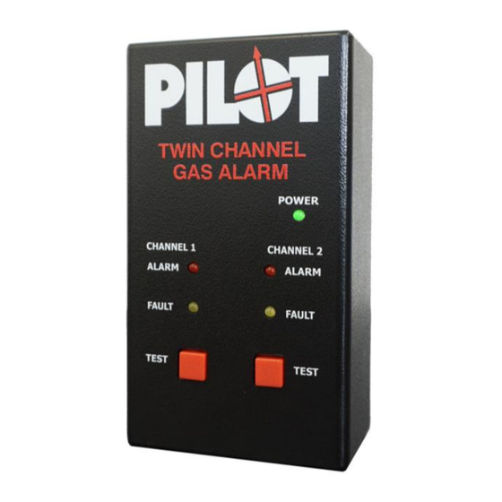
2.1 Front Panel & LED Indicators The first LED on the front panel of your Twin Channel Gas Alarm is the Power Indicator. This LED illuminates green when the unit is powered on. State Power The unit is power on correctly. - Page 7 Next, you will see two LED’s and a button for each channel. The first is the ALARM LED and will illuminate red when gas is detected. The second is the FAULT LED and will illuminate yellow when a fault is detected. The test button can be used to see if the unit alarm is operating correctly.
-
Page 8: Liquid Petroleum Gas Sensor
State Channel LED’s An OFF LED shows that the channel is operating correctly. SOLID yellow FAULT LED indicates a FAULT. Check all sensor wiring connections. SOLID red ALARM LED indicates the unit is ALARMING 2.2 Liquid Petroleum Gas Sensor The LPG sensors detect butane/propane and alarms at 25% LEL (lower explosive limit). -
Page 9: Technical Specification
2.3 Technical Specification Specification Value Description Supply Voltage 12/24V Supply from your system battery 140mA Current Draw When alarm not (Standby) sounding 140mA Current Draw When alarm is (Alarming) sounding Number of Supports 2 LPG sensors sensors Dimensions 70 x 40 (W) x (D) x (H) x115... -
Page 10: Installation
• The power supplied must come from the vessel’s Master Switch in order to activate the Gas Alarm whenever the power is on. • The Twin Channel Gas Alarm will work on a 12V or 24V supply. Suitable Installation Locations •... -
Page 11: Wiring
3.1 Wiring WARNING Disconnect the power supply before proceeding • Using the wiring diagram on page 11, start from pin 1 and work your way along the terminal block inserting the wires into the block. • Wires are secured using a flat head screwdriver. •... -
Page 12: Pin Definitions
3.2 Pin Definitions Wiring Diagram Positive power supply Negative power supply (Common Ground) Sensor 1 Positive Sensor 1 Negative Sensor 1 Signal Sensor 2 Positive Sensor 2 Negative Sensor 2 Signal Not Used Not Used Not Used... -
Page 13: Initialisation & Testing
4.1 Initialisation The initialisation process will occur every time your Twin Channel Gas Alarm is powered on. The green LED will illuminate, and the red LED will flash every second alongside a beeping sound. During this time the unit will check for attached sensors and start the initialisation process. -
Page 14: Testing
4.2 Testing The alarm may be tested at any time in two ways: By pressing the “Test” button on the front of your unit. This simulates the presence of harmful gases and should immediately sound the alarm and illuminate the red LED. By allowing a small amount of lighter fluid vapour to pass by the LPG sensors. -
Page 15: Alarm
5. Alarm • Constant, high pitch alarm noise. • “ALARM” LED will illuminate RED. ACTION In the event of an alarm ensure that nothing is used which could ignite gas (matches, engine ignition etc.). Ventilate the area by opening doors and hatches. -
Page 16: Troubleshooting
6. Troubleshooting Symptom Possible Cause Action Intermittent Sensor may have Switch off supply, Alarm become check connections, disconnected restart. Otherwise replace the sensor Frequent Contaminated Replace the sensor false alarms Sensor or other gases present. Sensor over 2 years old Regular Low supply Check boat power... -
Page 17: Sensor Replacement
If your issue is not listed here, please use the contact details on the back of this manual to contact the manufacturer/supplier. 7. Sensor Replacement We recommend that you replace your sensors every 2 years as their sensitivity can change over time. -
Page 18: Warnings
8. Warnings DO NOT: Expose sensors to silicone vapours, alkaline metals or a highly corrosive environment Use cleaning products around the sensors Allow the sensors to become damp or wet Expose the sensors to extreme temperatures (below 0°C or above 60°C) ... -
Page 19: Contact Details
9. Contact Details Website www.envinsci.co.uk Online Shop www.envinsci.co.uk/envin- shop Email info@envinsci.co.uk Telephone +44 (0)1829 771 792 Address Envin Scientific Limited Technology House Chowley Oak Tattenhall Chester CH3 9GA...
Need help?
Do you have a question about the Twin Channel Gas Alarm and is the answer not in the manual?
Questions and answers