Table of Contents
Advertisement
Quick Links
Advertisement
Table of Contents

Summary of Contents for Pilot Communications 2011319/716/12
- Page 1 Gas Monitoring System & Twin Channel Gas Alarm Operation and Maintenance Manual...
-
Page 3: Table Of Contents
Contents Introduction....................1 Gas Monitoring System.................1 Twin Channel Gas Alarm...............1 Technical Specifications................2 12v Gas Monitoring System – 2011319/716/12........2 24v Gas Monitoring System – 2011319/716/24........2 12v Twin Channel Gas Alarm – 2011112/716/12.........3 24v Twin Channel Gas Alarm – 2011112/716/24.........3 Installation....................4 Power Supply..................4 Suitable Installation Locations..............4... -
Page 4: Introduction
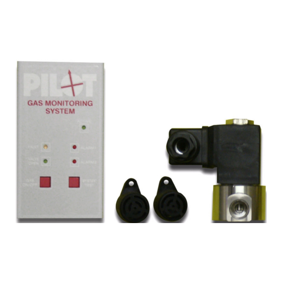
Introduction This user manual will cover the 12 and 24v version of both the Pilot Gas Monitoring System and the Twin Channel Gas Alarm. The Pilot range of gas monitoring alarms are important and cost effective items of safety equipment wherever LPG may be present. However good a gas installation may be, there is always a chance that a potentially lethal leak may occur. -
Page 5: Technical Specifications
Technical Specifications 12v Gas Monitoring System – 2011319/716/12 Spec. Value Description Supply Voltage 12v DC Current 650mA Standby – ¼” BSP Valve open 750mA Standby – ½” BSP Valve open 185mA Standby – Valve closed 200mA Alarm Mode Max. Sensors... -
Page 6: Twin Channel Gas Alarm - 2011112/716/12
12v Twin Channel Gas Alarm – 2011112/716/12 Spec. Value Description Supply Voltage 12v DC Current 180mA Standby 200mA Alarm Mode Max. Sensors Dimensions 120x65x35mm 24v Twin Channel Gas Alarm – 2011112/716/24 Spec. Value Description Supply Voltage 12v DC Current 55mA Standby 90mA Alarm Mode... -
Page 7: Installation
Installation Warning: Disconnect the power supply before proceeding with the installation. Power Supply The power supply will be either 12v or 24v depending on the • version of gas monitor that you have purchased (See Technical Specifications to check supply voltage). The power supply must come from the vessel's Master Switch •... -
Page 8: Valve - Gas Monitoring System Only
Valve – Gas Monitoring System Only The solenoid valve should be connected down stream of the • regulator and as close to it as possible. The base of the valve is marked “1” and “2” for gas in and gas •... - Page 9 Connections to Circuit Board: All of the connections for the PCB terminals are shown at • the bottom of this section (Diagram 2). The terminals are also labelled on the PCB. Terminals 9 and 10 are not used for the Twin Channel •...
-
Page 10: Operation
Operation Initialisation Process When the unit is powered on, the green LED will illuminate. • The remaining three lights will flash and an intermittent • audible alarm will sound for approximately 30 seconds. The initialisation process may take up to 8 minutes. However, •... -
Page 11: Valve And Testing
Valve and Testing To open the valve, push the gas on/off button. • Note: The valve can only be opened once the sensors have • stabilised and will also automatically close if the alarm goes off. To reconnect the gas supply after the alarm has stopped, press •... -
Page 12: Warnings
Warnings DO NOT: Expose sensors to silicone vapours, alkaline metals or a highly • corrosive environment. Use cleaning products around the sensors. • Submerge the sensors in water. • Expose the sensors to extreme temperatures. (Between -10°C • and 60°C is the recommended operating temperature) Replace the sensors every 2 years. -
Page 13: Troubleshooting
Troubleshooting Symptom Possible Cause Action Yellow LED with A red or yellow sensor Switch off, check intermittent alarm wire may be connections, restart. disconnected Otherwise, replace the sensor Alarm LED with Alarm A black sensor wire See above may be disconnected Frequent false alarms Contaminated sensor / Replace sensor... -
Page 14: Spares
Spares Replacement sensors and valves are available from the Envin Scientific online shop. See Contact on page 12 for website and online shop information. Sensors Part No. Description 201115 Sensor only 201115-3.5 Sensor with housing and 3.5 meter cable 201115-C Sensor with housing, 150mm cable and connector block. -
Page 15: Contact
Contact Website www.envinsci.co.uk Online Shop www.envinsci.co.uk/envin-shop Email info@envinsci.co.uk Telephone +44 01829 771 792 Address Envin Scientific Limited Technology House Chowley Oak Tattenhall Chester Cheshire CH3 9GA...


Need help?
Do you have a question about the 2011319/716/12 and is the answer not in the manual?
Questions and answers