Table of Contents
Advertisement
Quick Links
Advertisement
Table of Contents

Related Manuals for Meteo Control blue’Log X Series


Summary of Contents for Meteo Control blue’Log X Series
- Page 1 blue’Log X series (X-1000 / X-3000) Operating manual Version 20150201...
- Page 2 Copyright Copyright for this manual remains with the manufacturer. No part of this manual may be reproduced or edited, duplicated or distributed using electronic systems without written permission from meteocontrol GmbH. Compensation shall be payable in the event of any copyright infringements. All brand names mentioned in this manual are the property of their respective manufacturers and are hereby acknowledged.
-
Page 3: Table Of Contents
Contents General notes ....................4 Safety instructions ..................4 Warning symbols ..................4 Additional information ................. 5 Text display ....................5 Notes on this operating manual ................6 Warranty and liability ................... 6 Safety instructions for operation ................. 7 Intended use ....................7 Personnel .................... - Page 4 CAN interface ................... 23 USB interface.................... 23 Start-up, configuration ..................24 Prerequisites ..................... 24 Start-up ..................... 24 Making/checking connections..............24 7.3.1 Ethernet connection ................. 24 7.3.2 Bus device connection ................25 7.3.3 Connections to analog/digital inputs ............25 Display log-in..................... 26 7.4.1 Start menu ....................
- Page 5 11. Technical data ....................47 12. Environmental protection and disposal ............. 50 12.1 List of figures .................... 51 blue’Log X series 3| 52...
-
Page 6: General Notes
General notes Safety instructions Safety instructions warn of dangers when using the devices and explain how they can be avoided. The safety instructions are classified according to the severity of the risk and are subdivided into four groups: DANGER Imminent danger Failure to comply with the warning notice will lead to an imminent risk of death or serious physical injury! WARNING... -
Page 7: Additional Information
Additional information This symbol can be found next to notes, additional information and tips. Text display Emphasized points are shown in bold and indicate important information. Lists are shown with bullet points (level 1) and dashes (level 2): List 1 Point A ... -
Page 8: Notes On This Operating Manual
Notes on this operating manual This manual is a key aid when it comes to ensuring proper operation of the device. It contains important information and safety notes to help you use the devices correctly, economically and in the intended manner. The manual helps to avoid dangers, to reduce repair costs and downtimes, and to increase the reliability and operating life of the devices. -
Page 9: Safety Instructions For Operation
Safety instructions for operation Intended use Only the permitted signals and signal strengths may be applied to the connections of the data logger (blue’Log) and the expansion modules (MX modules) described in this manual. Installation is only permitted indoors. For installation outdoors or in a dusty environment, the device must be installed in a standardized protective enclosure. -
Page 10: Protection Concepts
Protection concepts The memory card (SD memory) must not be removed while the blue’Log is in operation The blue’Log may not be opened The blue’Log may not be modified Damaged devices must be taken out of operation immediately and checked by a qualified electrician ... -
Page 11: Battery
Battery The blue’Log data logger comes with an internal lithium battery (button cell) which ensures that the time and date remain stored in the device in the event of a power cut. ATTENTION Lithium battery On no account may the battery be replaced by the customer or even a qualified electrician, as the casing has to be opened for this procedure. -
Page 12: Device Overview
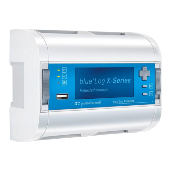
Device overview Overview of versions blue’Log X-1000 blue’Log X-3000 Max. feed-in power in kWp 1000 Storage capacity 16 GB 16 GB blue’Log front panel Fig. 1: Overview blue’Log front panel Digital input (DI1 – DI4) RS485/422 termination – 2 (10) RS485/422 - 2 CAN termination (11) -
Page 13: Blue'log Rear Panel
blue’Log rear panel Fig. 2: Overview blue’Log rear panel Clamp for DIN rail Status LEDs The front panel holds three LED displays, which are explained below. Symbol Meaning Green: blue‘Log is supplied with power Off: No power supply Green: System loaded successfully, normal operation Orange: System booting, boot phase Red: System error... -
Page 14: Installation
Installation Safety instructions for installation DANGER Risk of electrocution! Fatal injuries or death from contact with cables and terminals. Only connect or disconnect cables while they are de-energized. Safeguard the feeding system from unintentional restart. ATTENTION Damage due to improper wiring! Incorrect wiring may lead to damage or destruction of measuring inputs and the device. -
Page 15: Cables And Wiring
Cables and wiring Recommended cable types for wiring the individual system components are given below. The restrictions resulting from the wiring are listed as well. 5.2.1 Permitted cable types for the blue’Log power supply Power cable for supply voltage Voltage range Cable cross-section U <... -
Page 16: Maximum Recommended Cable Lengths
5.2.3 Maximum recommended cable lengths 1200 m 2) 3) Bus cabeling (RS485 data cable) 100 m Sensors (voltage signal 0 V – 10 V) 600 m Sensors (current signal 4 mA – 20 mA) 10 m Meters 100 m ... -
Page 17: Installation
Installation 5.3.1 Installing device on DIN rail Hang the blue’Log on the top-hat rail using the clamping fixture (rear panel). Move the DIN rail slider situated on the front panel from bottom (latch open) to top (latch closed) position. This will fix the blue’Log to the DIN rail. The symbols (open/closed lock) above and below the slider indicate the current status of the fixation. -
Page 18: Expansion Of The Blue'log System
Expansion of the blue’Log system The blue’Log can be upgraded with additional interfaces using various expansion modules (MX modules). Fig. 4: MX modules (example: RS485/422) ATTENTION Risks when adding expansion modules An installation of MX-Modules while the blue’Log is in operation, can lead to damage or destruction of the blue’Log and its expansion modules. -
Page 19: Installation Of The Expansion Modules
5.4.1 Installation of the expansion modules In order to expand the blue’Log, remove the cover on the right-hand edge of the casing by unlocking the four corresponding case locks Fig. 5: Opening the case locks Fig. 6: Right side cover removed Keep the side cover at hand. - Page 20 Now install the desired expansion module by plugging it into the blue’Log socket. Fig. 8: Attaching expansion module to the blue’Log. Close the blue’Log's case locks to fix the expansion module in place. Fig. 9: Attached expansion module 18| 52 blue’Log X series...
- Page 21 Reattach the previously removed blue’Log side cover to the right side of the expansion module and fasten it by closing the case locks. Fig. 10: blue’Log and MX module connected with side covers attached blue’Log X series 19| 52...
- Page 22 An extension of the blue'Log with several equal MX modules is possible, as well as the extension with different MX modules. The maximum number of connectable expansion modules is listed in the data sheet of the base unit. Fig. 11: blue’Log with several MX modules ATTENTION Order for installation of MX-Modules When connecting the MX modules in the wrong order on the base unit, a...
-
Page 23: Interfaces
Interfaces Power supply 6.1.1 Device protection 10…60 V DC Voltage: 1.3…8.0 A Current: Alternative 1 To limit the power consumption of the blue'Log a DC power supply with power limiter and a maximum output current of 8 A has to be used. Alternative 2 If the dimensioning mentioned under Alternative 1 is not possible due to local infrastructure, the device protection must be carried out via appropriate pre-... -
Page 24: Device Protection When Wall-Mounted
6.1.2 Device protection when wall-mounted Voltage: 24 V DC 1.6 … 6.2 A Current: To limit the power consumption of the blue'Log a DC power supply with power limiter and a maximum output current of 6.2 A has to be used A suitable power supply can be found in the meteocontrol product portfolio: AC/DC Adapter HN-Power, type HNP 36EU-240 ATTENTION... -
Page 25: Digital Input
Digital input The digital inputs are freely configurable as: Pulse input in accordance with DIN 43864 (S0) Voltage level input: 0-24 V DC Dry contact: 24 V DC / 20 mA The four digital inputs are multi inputs either for analog or digital signals, to be configured per port via software. -
Page 26: Start-Up, Configuration
Start-up, configuration Prerequisites Before commissioning the blue’Log, the device must be securely mounted and all cables connected correctly. Start-up To start up the system, the following steps are required: Switch on the power supply Wait until the blue‘Log has finished booting. The status LED on the device lights up. -
Page 27: Bus Device Connection
7.3.2 Bus device connection The blue'Log comes with two RS485 / 422 interfaces for connection of bus devices. Connect your devices to the blue’Log via RS485/422 in accordance with the requirements set out in the "blue’Log M and X series device connection plans" document. -
Page 28: Display Log-In
Display log-in 7.4.1 Start menu To bring up the settings menu, confirm the start screen by pressing the "OK" button. During first log-in you will be prompted to select a user. Fig. 12: blue’Log display: Start menu 7.4.2 User selection In this menu, registered users in the blue'Log are displayed. -
Page 29: Display Network Configuration
Display network configuration 7.5.1 DHCP Network parameters, such as the IP address, can be automatically received if a DHCP server can be located in the network. Therefore DHCP must be activated in the data logger. Navigate to network settings using the directional pad and the buttons: Main menu ... -
Page 30: Static Ip Address
7.5.2 Static IP address To set static network parameters such as IP address, subnet mask, gateway and DNS server, follow the instructions below: Navigate to network settings using the directional pad and the buttons: Main menu Telecommunication Network Deactivate the "DHCP"... -
Page 31: Logging On To Device Websites / Wizard
Logging on to device websites / wizard Further configurations can be made via the websites of the device. Furthermore the websites contain information about the operating status of your PV-system. To address your blue'Log enter the IP address into the address field of your Web browser. - Page 32 Fig. 17: blue’Log wizard information message Using a navigation bar, the wizard guides you step by step through the main set-up points necessary for normal operation. Select individual menu points by using the arrows (left and right) and the numbered points. Fig.
-
Page 33: Logger Basic Data
Logger basic data The basic data of the data logger are displayed or can be changed in this menu “Logger Basic-Data”. To enter this menu, follow these steps: Navigate to the "System" area via the top navigation bar. Navigate to the "Basemodule" area via the left-hand navigation menu and click on "Logger basic data". -
Page 34: Mx Modules
MX modules If you have extended the blue'Log data logger with one or more MX-module, the connected MX modules are listed on the "MX modules" website. Navigate to the "System" area via the top navigation bar. Navigate to the "MX modules" area via the left-hand navigation menu. After expansion of the blue’Log data logger with one or more MX modules, the MX ... -
Page 35: Date / Time
7.11 Date / time To set the date and time, proceed as follows: Navigate to the "System" area via the top navigation bar. Navigate to the "Basic module" area via the left-hand navigation menu and select "Date / time". Three different settings are available for "time synchronization", selected via the drop-down menu. -
Page 36: Basic-Data
7.12 Basic-data In the menue „PV-Plant“ „Basic-Data“ informations of the PV-Plant can be saved. The information is used for documentation and may be taken into account and transferred during portal registration. Navigate to the "PV system" area via the top navigation bar. Navigate to the "Master data"... -
Page 37: Set Up New System Using Master Data
7.13.2 Set up new system using master data A new system can be set up using the system master data and your portal access data. The system configuration can be finalized in the portal. To set up a system, the following portal access data are necessary: ... -
Page 38: Ftp Push
7.15 ftp push With this function, data can be sent to an independent ftp server in addition to the meteocontrol online portal safer'Sun. Navigate to the "PV system" area via the top navigation bar. Navigate to the "Online portal" area via the left-hand navigation menu and select "Push service". -
Page 39: Recording Of Devices
Recording of devices Sensors Navigate to the "Devices" area via the top navigation bar. Navigate to the "Sensors" area via the left-hand navigation menu. Fig. 20: Device websites: Add new sensor Via the drop-down menu, select the sensor model connected to the input of the blue’Log data logger (e.g. - Page 40 The following preconfigured parameters may be adopted as they stand: Unit Gradient Offset To review the presets, please use the enclosed "blue’Log M and X series device connection plans" document. Adjust the parameters if necessary. As soon as "Save" is selected, the sensor will be recorded and listed under "Sensor overview".
-
Page 41: Meters
Meters Navigate to the "Devices" area via the top navigation bar. Navigate to the "Meters" area via the left-hand navigation menu. Fig. 22: Device websites: Add new meter Via the drop-down menu, select the option S0 energy meter. Further settings will be made available in the configuration menu. - Page 42 The following preconfigured parameters may be adopted as they stand: Unit Pulse constant To review the presets, please used the enclosed "blue’Log M and X series device connection plans" document. Adjust the parameters if necessary. As soon as "Save" is selected, the meter will be recorded and listed under "Meter overview".
-
Page 43: Inverters
Inverters Navigate to the "Devices" area via the top navigation bar. Navigate to the "Inverters" area via the left-hand navigation menu. Fig. 24: Device websites: Add new inverter Via the drop-down menu, select the manufacturer of the connected inverter (e.g. Kaco). -
Page 44: Visualization
Visualization Sensors Navigate to the "Cockpit" area via the top navigation bar. Navigate to the "Diagrams" area via the left-hand navigation menu and select "Sensors". Fig. 26: Device websites: Selecting diagram options – sensors Select those sensor(s) you would like to visualize the measured values of. Select the available measured values. -
Page 45: Meters
Meters Navigate to the "Cockpit" area via the top navigation bar. Navigate to the "Diagrams" area via the left-hand navigation menu and select "Meters". Fig. 27: Device websites: Selecting diagram options – meters Select those meter(s) you would like to visualize the measured values of. Select the available measured values. -
Page 46: Inverters
Inverters Navigate to the "Cockpit" area via the top navigation bar. Navigate to the "Diagrams" area via the left-hand navigation menu and select "Inverters". Fig. 28: Device websites: Selecting diagram options – inverters Select those inverter(s) you would like to visualize the measured values of. Select the available measured values. - Page 47 At selection of "Show diagram", the configuration will close and the diagram view is displayed. Fig. 29: Device websites: Visualizing measurement data – inverters blue’Log X series 45| 52...
-
Page 48: Messages
10. Messages 10.1 Logbook Navigate to the "Cockpit" area via the top navigation bar. Navigate to the "Logbook" area via the left-hand navigation menu. Fig. 30: Device websites: Logbook System events (max. 500 entries) are listed in the logbook. Entries can be sorted according to "Time", "Error code", "Error type" and "Description"... - Page 49 11. Technical data TECHNICAL DATA Power supply 10-60 V DC Power consumption Typically 5 W Max. 80 W, inclusive MX-Modules ESD protection Tested in accordance with DIN EN 61000-4-2 (4 kV contact discharge, 8 kV air discharge) Operating temperature -20°C to 70°C Storage and transport temperature -20°C to 85°C Protection class...
- Page 50 Digital Inputs 4 x digital inputs (mode per port individually configurable via software) The following options are available for each input: Type Usage Range Precision Resolution Digital Potential-free contact 24 V DC / 20 mA Digital S0- compliant Digital Outputs / Multi Inputs Each of the four ports has a pin for a digital output, a multi input and a ground: 4 x digital outputs (mode per port individually configurable via software) 4 x multi inputs (mode per port individually configurable via software)
- Page 51 DRIVERS Supported inverters The system is supplied with all inverter drivers available at the time of production. These can be assigned variably to the corresponding interface on the blue’Log. The number of supported inverter manufacturers is increasing all the time. For more information, see the blue’Log driver data sheets at http://www.meteocontrol.com/de/downloads/.
- Page 52 12. Environmental protection and disposal Old devices which no longer work should be disposed of in accordance with national and local environmental and recycling regulations. Electronic components may not be disposed of along with household waste. 50| 52 blue’Log X series...
- Page 53 12.1 List of figures Fig. 1: Overview blue’Log front panel ................10 Fig. 2: Overview blue’Log rear panel ................11 Fig. 3: Secure mounting on a DIN rail ................15 Fig. 4: MX modules (example: RS485/422) ..............16 Fig. 5: Opening the case locks ..................17 Fig.
- Page 54 52| 52 blue’Log X series...
- Page 56 Spicherer Str. 48 D-86157 Augsburg Phone +49 (0) 821 / 3 46 66-88 Fax +49 (0) 821 / 3 46 66-11 technik@meteocontrol.de www.meteocontrol.com Text and illustrations represent state-of-the-art technology at the time of printing Subject to technical modifications We assume no liability for printing errors.
Need help?
Do you have a question about the blue’Log X Series and is the answer not in the manual?
Questions and answers