Table of Contents
Advertisement
Advertisement
Table of Contents

Related Manuals for Baumuller BUG 3

Summary of Contents for Baumuller BUG 3
- Page 1 DATASHEET BAUMÜLLER BUG2-60-31-B-010 OTHER SYMBOLS: RGB ELEKTRONIKA AGACIAK CIACIEK SPÓŁKA JAWNA Jana Dlugosza 2-6 Street 51-162 Wrocław www.rgbelektronika.pl Poland biuro@rgbelektronika.pl +48 71 325 15 05 www.rgbautomatyka.pl www.rgbautomatyka.pl www.rgbelektronika.pl...
- Page 2 YOUR PARTNER IN MAINTENANCE Repair this product with RGB ELEKTRONIKA ORDER A DIAGNOSIS LINEAR ENCODERS SYSTEMS INDUSTRIAL COMPUTERS ENCODERS CONTROLS SERVO AMPLIFIERS MOTORS MACHINES OUR SERVICES POWER SUPPLIERS OPERATOR SERVO PANELS DRIVERS At our premises in Wrocław, we have a fully equipped servicing facility. Here we perform all the repair works and test each later sold unit.
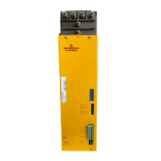
- Page 3 BAUMÜLLER BASIC FEED UNIT BUG 3 / 2 / 20 Technical description and operation manual 5.96064.02 Edition 15. February 2002...
- Page 4 BAUMÜLLER BASIC FEED UNIT BUG 3 / 2 / 20 Technical description and operation manual Edition March 1997 5.96064.01 PLEASE READ AND PAY ATTENTION TO SAFETY INSTRUCTIONS AND OPERATING GUIDE PRIOR TO COMMISSIONING This manual contains the necessary information for normal opteration of the products described therein.
-
Page 5: Table Of Contents
5 Installation ......................17 5.1 Danger Information......................17 5.2 EMC Information......................18 5.3 Connection Diagram......................24 5.3.1 BUG 2 ......................25 5.3.2 BUG 3 ......................24 5.3.3 BUG 20 ......................26 5.3.4 Connection Information..................27 5.4 Pin Assignments......................28 5.4.1 Power Terminals....................28 5.4.2 Control Terminals .................... 28 5.5 Accessories ........................29... - Page 6 7 Maintenance....................... 49 7.1 Maintenance Information ....................49 7.2 Disposal ...........................50 8 Appendix ......................51 8.1 Manufacturer Declaration ....................51 8.2 Declaration of Conformity ....................52 8.3 Conditions of Business and Delivery ................53 8.4 Index ..........................54 BUG 3/2/20 Basic Feed Unit Baumüller Nürnberg GmbH 5.96064.02...
- Page 7 Baumotronic Converter Servo Power Unit Direct current German Standardization Institute (Deutsches Institut für Normung e.V.) Electromagnetic compatibility European standard Main contactor Intelligent Power Module Mean sea level Protective earth Synchronous motor Intermediate circuit BUG 3/2/20 Basic Feed Unit Baumüller Nürnberg GmbH 5.96064.02...
- Page 8 Abbreviations BUG 3/2/20 Basic Feed Unit Baumüller Nürnberg GmbH 5.96064.02...
-
Page 9: Safety Information
The equipment/system is manufactured using state-of-the-art technology and is safe in operation. It can safely be installed and commissioned and functions without problems if the safety information below is followed. BUG 3/2/20 Basic Feed Unit Baumüller Nürnberg GmbH 5.96064.02... - Page 10 This means that death, severe personal injury, or considerable damage to property may occur unless appropriate safety measures are taken. NOTE This draws your attention to important information about the product, handling of the product or to a particular section of the documentation. Basic Feed Unit BUG 3/2/20 Baumüller Nürnberg GmbH 5.96064.02...
- Page 11 The machine minder must report immediately any changes that occur which adversely affect the safety of the equipment/system. Appropriate use also includes observing the operating instructions and complying with the conditions of inspection and maintenance. BUG 3/2/20 Basic Feed Unit Baumüller Nürnberg GmbH 5.96064.02...
- Page 12 Safety Information BUG 3/2/20 Basic Feed Unit Baumüller Nürnberg GmbH 5.96064.02...
-
Page 13: Technical Data
E version with a connector for external resistors. Features: − BUG 3 basic unit for up to 10.5 kW − BUG 2 basic unit for up to 18 kW − BUG 20 basic unit for up to 36 kW −... -
Page 14: Description Of Function
If this voltage exceeds an impermissibly high value, the integrated ballast transistor switches the ballast resistor (which can be external if desired) to the intermediate circuit and removes the excess energy. BUG 3/2/20 Basic Feed Unit Baumüller Nürnberg GmbH 5.96064.02... -
Page 15: Block Diagram
Ballast ON for t > 1.5 s TKK, is too high Operating TB H6 lights up red Uzk H5 lights up red +/- 15 V H4 lights up red TKK H3 lights up red indicator BUG 3/2/20 Basic Feed Unit Baumüller Nürnberg GmbH 5.96064.02... -
Page 16: Electrical Data
Technical Data Electrical Data 2.2 Electrical Data Basic Feed Unit BUG 3 - 35 - 30 BUG 2 - 60 - 30 BUG 20 - 120 - 30 Connection voltage 3 x 230 V +10 %/-15 % 50/60 Hz Intermediate circuit power 10.5 kW... - Page 17 The same conditions apply as before. Characteristic curve 1: Load in dependence on the site elevation Load in dependence on installation height 1000 2000 3000 4000 5000 Installation height [m] BUG 3/2/20 Basic Feed Unit Baumüller Nürnberg GmbH 5.96064.02...
-
Page 18: Type Code
Technical Data Type Code 2.3 Type Code BUG 3/2/20 Basic Feed Unit Baumüller Nürnberg GmbH 5.96064.02... -
Page 19: Transportation, Unpacking
If the unit has been damaged in transit, do not connect it to the mains until appropriate high-voltage testing has been carried out. Ignoring this information can result in death, severe personal injury, or considerable damage to property. Environmental conditions must be regulated according to pr EN 50178. BUG 3/2/20 Basic Feed Unit Baumüller Nürnberg GmbH 5.96064.02... - Page 20 Transport, Unpacking BUG 3/2/20 Basic Feed Unit Baumüller Nürnberg GmbH 5.96064.02...
-
Page 21: Assembly
Electrical components must not be mechanically damaged or destroyed as this could lead to health risks! WARNING Lifting incorrectly can result in personal injury or damage to property. The device should only be lifted by appropriately qualified personnel using the proper equipment. BUG 3/2/20 Basic Feed Unit Baumüller Nürnberg GmbH 5.96064.02... -
Page 22: Dimensions
Assembly Dimensions 4.1 Dimensions BUG 3/2/20 Basic Feed Unit Baumüller Nürnberg GmbH 5.96064.02... - Page 23 Dimensions Assembly Fastening Holes BUG 3/2/20 Basic Feed Unit Baumüller Nürnberg GmbH 5.96064.02...
-
Page 24: Assembly Information
• Install the units vertically in a switching cabinet. Mount the BUS 3/21/20 servo power units next to the BUG 3/2/20 basic feed unit and connect the intermediate circuit using the supplied rails. DANGER... -
Page 25: Installation
Be particularly careful before touching the drive shaft directly or indirectly with your hands. This is only allowed when the system is deenergized and the drive is stationary. Safety devices must never be deactivated. BUG 3/2/20 Basic Feed Unit Baumüller Nürnberg GmbH 5.96064.02... -
Page 26: Emc Information
This does justice to the fact that EMC is heavily dependent on the individual subassemblies and com- ponents in the switching cabinet. With regard to the total costs of the machine, it is preferable to trou- bleshoot an entire system rather than each of its individual components. BUG 3/2/20 Basic Feed Unit Baumüller Nürnberg GmbH 5.96064.02... - Page 27 Operator Panel Distance of at least 20 cm Lines routed via metallic conduit threads or connector housing with connected screen Screen's point of contact with mounting plate Screened Line Unscreened Line BUG 3/2/20 Basic Feed Unit Baumüller Nürnberg GmbH 5.96064.02...
- Page 28 • Sources of interference such as fuses, transformers and chokes and modules that are sensitive to interference like µPs, bus systems, etc. should be located at least 20 cm away from the converter and its cabling. BUG 3/2/20 Basic Feed Unit Baumüller Nürnberg GmbH 5.96064.02...
- Page 29 The distance of the last screen contact point to the exit from the cabinet must be as short as possible. BUG 3/2/20 Basic Feed Unit Baumüller Nürnberg GmbH 5.96064.02...
- Page 30 The following lines have particularly high levels of interference potential: − the motor line − the line to the external ballast resistors − the line between the mains filter and the converter BUG 3/2/20 Basic Feed Unit Baumüller Nürnberg GmbH 5.96064.02...
- Page 31 100 mA and higher. This means that converters with earth leakage circuit-breakers may be incompatible! In this context, you should observe the safety information in provisional standard EN 50178:1994 Section 5.2.11.2. BUG 3/2/20 Basic Feed Unit Baumüller Nürnberg GmbH 5.96064.02...
-
Page 32: Connection Diagram
To further To further servo units servo units (SELV) K1 Controller enable (SELV) Reset +15 V SELV -15 V +24 V Ready 230 V pot.-free 230-V additional feed To NC ground potential-free! BUG 3/2/20 Basic Feed Unit Baumüller Nürnberg GmbH 5.96064.02... -
Page 33: Bug 2
Connection Diagram Installation 5.3.2 BUG 2 BUG 3/2/20 Basic Feed Unit Baumüller Nürnberg GmbH 5.96064.02... - Page 34 Installation Connection Diagram 5.3.3 BUG 20 BUG 3/2/20 Basic Feed Unit Baumüller Nürnberg GmbH 5.96064.02...
-
Page 35: Bug 20
Intermediate circuit connection to the BUS units via the supplied busbars. With several servo units, arrange the BUG in the middle. ZK+, ZK- Wire the BUG 3 with 4 mm² wires. DANGER When using autotransformers, the intermediate circuit carries mains potential;... -
Page 36: Pin Assignments
Intermediate circuit connection to the servo power units via the supplied bus- bars. Arrange the BUG in the middle of the servo power units. Wire the intermediate circuit from the BUG 3 and the servo power units with 4 mm² wires. DANGER When using autotransformers, the intermediate circuit carries mains poten- tial;... -
Page 37: Accessories
S1 at 40° C Type of Protection IP 00, Insulation class E IP 00, Insulation class E Ambient Temperature +40° C max. +40° C max. Do not connect the star point to the mains BUG 3/2/20 Basic Feed Unit Baumüller Nürnberg GmbH 5.96064.02... - Page 38 ... 7167 78.0 Starting current limitation device 0: Not necessary 1: Operation with starting current limitation device only These transformers have an additional tap for 190 V; 40-kVA transformers on request BUG 3/2/20 Basic Feed Unit Baumüller Nürnberg GmbH 5.96064.02...
- Page 39 5.8x11 19007160 136x56 7.0x14 19007161 15.0 175x85 7.0x14 19007162 22.5 200x100 9.0x14 19007163 27.0 220x105 8.5x12 19007165 10.0 29.0 220x105 9.0x14 19007166 15.0 51.0 280x110 12.0x8.5 19007167 25.0 78.0 340x130 9.0x14 BUG 3/2/20 Basic Feed Unit Baumüller Nürnberg GmbH 5.96064.02...
-
Page 40: Starting Current Limitation Device
Max. closing energy 350 Ws Max. capacitance at U =340 V 6 mF ZKmax Overload protection by safety circuit Rated current 2 A breaker with auxiliary switches Trip curve C Dimensions BUG 3/2/20 Basic Feed Unit Baumüller Nürnberg GmbH 5.96064.02... - Page 41 Accessories Installation Connection Suggestion BUG 3/2/20 Basic Feed Unit Baumüller Nürnberg GmbH 5.96064.02...
-
Page 42: Bur Resistor Unit
Stored energy − Ballast energy The following are stored in the ca- pacitor with BUG 3 and BUG 21 = 3.8 Ws/unit with BUG 20 and BUG 2 = 17.25 Ws/unit BUK capacitor unit = 345 Ws/unit The following are burnt out in the... - Page 43 Connections Type Code B U R - 6 2 2 - 0 4 - 2 - 0 0 0 BAUMOTRONIC Resistor Unit Type Series Type Resistor Rated power 2 kW Version BUG 3/2/20 Basic Feed Unit Baumüller Nürnberg GmbH 5.96064.02...
- Page 44 Installation Accessories Dimensions BUG 3/2/20 Basic Feed Unit Baumüller Nürnberg GmbH 5.96064.02...
-
Page 45: Buk Capacitor Unit
BUK 622 - 31- 20: approx. 640 Ws (U1 = 310 V, U2 = 400 V) BUK 622 - 54- 5: approx. 870 Ws (U1 = 540 V, U2 = 800 V) BUG 3/2/20 Basic Feed Unit Baumüller Nürnberg GmbH 5.96064.02... - Page 46 Installation Accessories Connection To intermediate circuits ZK+ and ZK- − with short 10-mm² wires for Series 2/20 type − with short 4-mm² wires for Series 3 type deenergized. Dimensions BUG 3/2/20 Basic Feed Unit Baumüller Nürnberg GmbH 5.96064.02...
- Page 47 5 4 - 0 5 - 0 0 0 BAUMOTRONIC Condenser Unit Type Series Size Rated Voltage 310 V or 540 V Capacity 20 mF at 310 V 5 mF at 540 V Design 000: standard xxx: customized BUG 3/2/20 Basic Feed Unit Baumüller Nürnberg GmbH 5.96064.02...
- Page 48 Installation Accessories BUG 3/2/20 Basic Feed Unit Baumüller Nürnberg GmbH 5.96064.02...
-
Page 49: Commissioning
Before carrying out commissioning, check whether the plastic covers over the power stage connec- tions are in place. The appliances are only to be operated on earthed mains systems. The discharge time of the power conducting parts is more than 1 minute. BUG 3/2/20 Basic Feed Unit Baumüller Nürnberg GmbH 5.96064.02... - Page 50 When dismounting safety equipment during commissioning, repair and maintenance, you must ensure that the machine is taken out of commission in accordance with applicable regulations. You must re- mount and check safety equipment immediately after completing commissioning, repair and mainte- nance. BUG 3/2/20 Basic Feed Unit Baumüller Nürnberg GmbH 5.96064.02...
- Page 51 Units containing components or modules at risk from electrostatic energy are clearly marked as such by the sticker below. BUG 3/2/20 Basic Feed Unit Baumüller Nürnberg GmbH 5.96064.02...
-
Page 52: Function Plan
Commissioning Function diagram 6.1 Function diagram BUG 3/2/20 Basic Feed Unit Baumüller Nürnberg GmbH 5.96064.02... - Page 53 -15 V -15 V BSa, BSn - Reference potential analog or n controller BSa, BSn H5 red Uzk intermediate circuit voltage > 400 V H6 red TB ballast resistor overloaded SELV BUG 3/2/20 Basic Feed Unit Baumüller Nürnberg GmbH 5.96064.02...
-
Page 54: Messages And Warnings
Ready-for-use is cancelled. This message is issued in the following cases: − braking energy is greater than P maxBallast − ballast circuit is missing − wrong or defective external ballast resistor BUG 3/2/20 Basic Feed Unit Baumüller Nürnberg GmbH 5.96064.02... - Page 55 If the system issues one of the messages listed above, it is stored and displayed as the System er- ror group message. The system cancels ready-for-use and reports it to the connected servo units. NOTE You cannot clear messages whose disturbances are still pending. BUG 3/2/20 Basic Feed Unit Baumüller Nürnberg GmbH 5.96064.02...
-
Page 56: Test Connector
- Braking power too high - Continuous power of ballast resistor output (X27:7) High too great - Brief load > 2 s Pmax - Intermediate circuit voltage > 375 V due to mains voltage BUG 3/2/20 Basic Feed Unit Baumüller Nürnberg GmbH 5.96064.02... -
Page 57: Maintenance
General Conditions of Business and Supply. 7.1 Maintenance Information The supplied units are maintenance-free. Prohibition of Unauthorized Modifications For safety reasons, unauthorized additions or modifications to the drive are not allowed. BUG 3/2/20 Basic Feed Unit Baumüller Nürnberg GmbH 5.96064.02... -
Page 58: Disposal
In case of fire, dangerous compounds can be generated or released. You must dispose of or recycle equipment or components according to national regulations as well as any applicable local or regional ordinances. BUG 3/2/20 Basic Feed Unit Baumüller Nürnberg GmbH 5.96064.02... -
Page 59: Appendix
BUG - 2 - 60 - 31 - . - ... - .. BUG - 20 - 120 - 31 - . - ... Date/Signature of the Manufacturer: Nürnberg, 4. März 1997 Information regarding the Undersigned: Head Division Electronics BUG 3/2/20 Basic Feed Unit Baumüller Nürnberg GmbH 5.96064.02... -
Page 60: Declaration Of Conformity
EN 50178: 1994 (VDE 0160/11.94) "Equipment of power installation concerned electronic operating materials" Nürnberg, 8. January 1997 Signature of the Manufacturer Dr.–Ing. P. Kreisfeld Dipl.–Ing. (FH) R.–A. Geller CE–Agent Electronic Head Division Electronics BUG 3/2/20 Basic Feed Unit Baumüller Nürnberg GmbH 5.96064.02... -
Page 61: Conditions Of Business And Delivery
20%. regulations corresponding to the economic purpose of the intended regulation to the largest possi- ble extent. The validity of the other regulations remains unchanged. BUG 3/2/20 Basic Feed Unit Baumüller Nürnberg GmbH 5.96064.02... -
Page 62: Index
Type Code • 10 EMC information • 18 Unpacking • 11 Filter Assembly • 23 Use, appropriate • 3 Filtering • 23 Ventilation • 16 Grounding • 21 WARNING • 2 BUG 3/2/20 Basic Feed Unit Baumüller Nürnberg GmbH 5.96064.02...
Need help?
Do you have a question about the BUG 3 and is the answer not in the manual?
Questions and answers