Table of Contents

Related Manuals for RIDGID Micro CM-100


Summary of Contents for RIDGID Micro CM-100
- Page 1 09/03/18 TECH DATA SHEET 68067 Micro CM-100 Digital Clamp Meter micro CM-100 micro CM-100 Digital Clamp Meter micro CM-100 Digital Clamp Meter Record Serial Number below and retain product serial number which is located on nameplate. Serial...
-
Page 2: Safety Symbols
CM-100 Digital Clamp Meter Safety Symbols In this operator’s manual and on the product, safety symbols and signal words are used to communicate important safety information. This section is provided to improve un- derstanding of these signal words and symbols. -
Page 3: Specific Safety Information
Specific Safety Information WARNING This section contains important safety information that is specific to this tool. Read these precautions carefully before using the RIDGID ® micro CM-100 Digital Clamp Meter to reduce the risk of electrical shock or other serious injury. -
Page 4: Description, Specifications And Standard Equipment
® product: • Contact your local RIDGID distributor. • Visit www.RIDGID.com or www.RIDGID.eu to find your local RIDGID contact point. • Contact Ridge Tool Technical Service Department at rtctechservices@emerson.com, or in the U.S. and Canada call (800) 519-3456. Description, Specifications And Standard Equipment... - Page 5 CM-100 Digital Clamp Meter Input Limits Function Maximum Input Voltage V DC/AC 600 V DC/AC Current A DC/AC 1000 A DC/AC Frequency, Duty Cycle 600 V DC/AC Accuracy is given at 18°C to 28°C (65°F to 83°F), less than 70% RH...
- Page 6 Test Current ........< 1.0 mA Standard Equipment The RIDGID ® micro CM-100 Digital Clamp Meter comes with the following items: • micro CM-100 Digital Clamp Meter • User Manual and Instruction CD • Test Leads with Covers, Black and Red •...
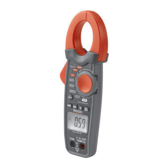
- Page 7 10. Positive Input Terminal for DC/AC Voltage Measure- ment, Resistance Measurement, Continuity Check, Diode Test, Frequency Measurement, Capacitance Measurement and Temperature Measurement 11. COM (Negative) Terminal for all measurements ( Figure 3 – micro CM-100 Digital Clamp Meter Controls Icons Screen Icons Icon Number Icons on Screen...
-
Page 8: Fcc Statement
EMC standards. However, the possibility of it causing interference in other devices can- not be precluded. Changing/Installing Batteries The RIDGID micro CM-100 Digital Clamp Meter is supplied without the battery installed. When the low battery [ ] icon appears on the display screen, replace the battery. Op- erating the clamp meter with a low battery can cause incorrect readings. -
Page 9: Pre-Operation Inspection
Set-Up and Operation WARNING Set up and operate the micro CM-100 Digital Clamp Meter ac- cording to these procedures to reduce the risk of injury from electric shock and other causes, and prevent tool damage. Use caution when working with voltages above 30 V AC RMS, 42 V AC peak or 60 V DC. - Page 10 CM-100 Digital Clamp Meter Do not connect to voltages that exceed 600 VAC or VDC relative to earth ground. This may damage the meter and expose the operator to a shock hazard. When using the probes, keep your fingers behind the finger guards on the probes.
-
Page 11: Input Terminals
CM-100 Digital Clamp Meter Input Terminals The black test lead plugs into the negative (COM) terminal and the red test lead plug the positive terminal. The Transformer Jaw Clamp is used for DC/AC current measurement. Terminals Description Ω / CAP /... -
Page 12: Dc/Ac Voltage Measurement
CM-100 Digital Clamp Meter DC/AC Voltage Measurement NOTI E Do not measure voltage if motor (or other high current equipment) on the cir- cuit is being switched ON and OFF. Large voltage surge may occur that can damage the meter. -
Page 13: Diode Test
CM-100 Digital Clamp Meter 1. Set the function switch to position. the “V Ω CAP TEMP Hz” terminal. 2. Insert the black test lead plug into the “COM” terminal and the red test lead plug into 3. Touch the test probe tips across the circuit or part under test. It is good practice to disconnect one side of the part under test so the rest of the circuit will not interfere with the resistance reading. -
Page 14: Frequency Measurement
CM-100 Digital Clamp Meter unplug cord, discharge all capacitors, etc.) to the circuit being measured before taking any capacitance measurement. Use the DC Voltage function to confirm that the capacitor is dis- charged. 1. Set the function switch to position. -
Page 15: Service And Repair
Storage The RIDGID micro CM-100 Digital Clamp Meter must be stored in a dry secure area be- tween -30°C (-22°F) and 60°C (140°F) and humidity less than 85% RH. Store the tool in a locked area out of the reach of children and people unfamiliar with the meter. -
Page 16: Battery Disposal
CM-100 Digital Clamp Meter Disposal Parts of the RIDGID micro CM-100 Digital Clamp Meter contain valuable materials and can be recycled. There are companies that specialize in recycling that may be found lo- cally. Dispose of the components in compliance with all applicable regulations. Contact your local waste management authority for more information.
Need help?
Do you have a question about the Micro CM-100 and is the answer not in the manual?
Questions and answers