Table of Contents
Advertisement
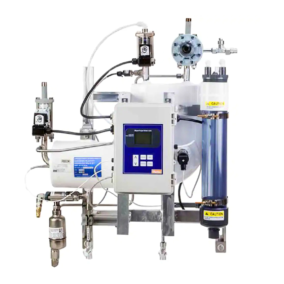
Rapid Purger
Product Bulletin 76-00 B
Type: V300
Purpose:
The V300 rapid purger from Parker
is designed to safely and efficiently
remove non-condensable gases
from ammonia refrigeration systems.
The V300 is an improvement over
the successful V200 series and
offers several new features and
benefits.
The V300 is equipped with a
RS-485 communication port for
easy interface to controller data
transmission. All of the parameters
accessible via the HMI cable
are now accessible via the serial
channel. Further advancements
include extended data logging time
and password protection for factory
calibration settings.
Like its predecessor the V200, the
V300 can be used with 120 or 240
VAC and can handle from 4 to 20
purge points.
Contact Information:
Parker Hannifin Corporation
Refrigerating Specialties Division
2445 South 25th Avenue
Broadview, IL 60155-3891
phone (708) 681-6300
fax (708) 681-6306
www.parker.com/refspec
Product Features:
• Safety relief provision
• Made from 100% corrosion free
components
• RS-485 communication capability
• Records purge cycles and purge
time up to 12 weeks
• Password protection prevents
tampering
• Multiple language display
• Factory calibrated for plug and play
functionality
• Automatically adjusts vent
pressures based on system
conditions
• Proprietary microprocessor control
for all sensing
• Includes 1/2" Globe-T SW isolation
valves for the liquid, foul gas and
suction lines
• Includes a 30"-150 psig ammonia
gauge and encapsulated leaded
coils
• Ammonia loss history
Advertisement
Table of Contents

Related Manuals for Parker V300


Summary of Contents for Parker V300
- Page 1 Like its predecessor the V200, the V300 can be used with 120 or 240 VAC and can handle from 4 to 20 purge points. Contact Information: Product Features:...
-
Page 2: Table Of Contents
Line system where the refrigerant is saturated, such as the condenser drain legs or high pressure receiver, as illustrated in Figure 1 . Auto Purger Figure 1: Purge Point (P) Locations (Model V300) -
Page 3: Purge Cycle
Purge points should be located to ensure no liquid refrigerant which is generally achieved by the use of a self-contained system is drawn into the purger . The Rapid Purger V300 has a liquid incorporating microprocessor controls . These are designed to... -
Page 4: Installation
Bulletin 76-00 B After going through the control orifice the foul gas passes Any oil that may collect in the V300 purger can be drained from over the tubes in the heat exchanger and residual refrigerant the two oil drains . Before draining the oil, shut-off the purger is condensed . - Page 5 Bulletin 76-00 B Make sure to leave access for servicing the unit if required . The 5 . Wait several minutes before welding the purger flanges to recommended clearance zone, as shown in Figure 5, is 254 mm the hand shut-off valves . Be certain the mating surface of the (10") for the top and sides .
- Page 6 Bulletin 76-00 B leads . The other coil lead should be attached to the N .O . or coil WARNING: Because both the water and vent solenoids are neutral terminal for each independent purge point solenoid energized at the same time, this procedure must be done prior (S6N, S8F) .
-
Page 7: Startup Instructions
Nameplate Information Item Description Year of Manufacture, Complete V300 Purger Serial Reference Number Canadian Registration Number (CRN) National Board Number (NB#) Year of Manufacture, Heat Exchanger Table 1 : V300 Rapid Purger Nameplate Identification Figure 10: V300 Rapid Purger Nameplates... -
Page 8: Password Setting Instructions
Bulletin 76-00 B Password Setting Instructions Password Setting Instructions Steps Setup Instructions Display Notes MAIN MENU START UP To set the Password for calibrating the SETUP Pressure Input or the RTD, press the HISTORY FACTORY TEST MODE (MENU) button to go to the secondary LANGUAGE MENU menu screen ∨... -
Page 9: Purge Type And Points Setting Instructions
Bulletin 76-00 B Purge Type and Points Setting Instructions Purge Type and Points Setting Instructions Steps Setup Instructions Display Notes MAIN MENU START UP SETUP To change the purge type, press the HISTORY (MENU) button to go to the main menu FACTORY TEST MODE screen. - Page 10 Bulletin 76-00 B Purge Type and Points Setting Instructions Continued Purge Type and Points Setting Instructions Steps Setup Instructions Display Notes SET PURGER END TIME ∧ ∨ Use the ( ) or ( ) buttons to enter the ENTER THE MINUTE: 20 If the Purge time is set for Greenwich Mean Time (GMT), end time minute within the hour set in jump to Step 11...
-
Page 11: Calibrate Pressure Input And Rtd
Bulletin 76-00 B Calibrate Pressure Input and RTD Calibrate Pressure Input and RTD Steps Setup Instructions Display Notes MAIN MENU START UP SETUP To calibrate the Pressure Input or the HISTORY RTD, press the (MENU) button to go to FACTORY TEST MODE the secondary menu screen LANGUAGE MENU ∨... -
Page 12: Remote Communications Setup/Assembly Instructions
To connect the CAT5 Ethernet cable to the GM-482422 converter follow below instructions . 1 . Measure the length of the CAT5 cable from the V300 Rapid Purger to the computer . 2 . Cut off one end of the CAT5 cable to expose the internal wires . -
Page 13: Gearmo Usb To Rs485 Adaptor Driver Installation Instructions
Bulletin 76-00 B Gearmo USB to RS485 Adaptor Driver Installation Instructions Gearmo USB to RS485 Adaptor Driver Installation Instructions Steps Setup Instructions Display Notes The driver is also available for download at http:// www.gearmo.com/shop/usb-to-rs485-rs422- converter-ftdi-chip-with-terminals/ If you choose to download the driver, proceed to Step 5 Insert the Gearmo FTDI driver CD into the computer of choice’s CD-... -
Page 14: Remote Communications Setup Instructions - Option 1
Feed the other end of the cable (RS845 side) through an unused hole at the bottom of the V300 Purger Controller enclosure. Plug in the RS845 (Cat5) connector to the RJ45 Jack on the Display... - Page 15 It is important to select the correct COM port that aligns with the RS-485 converter. This can be determined by starting the application on the PC with the RS485 converter unplugged from the V300 Select the COM port that is Purger Controller, then look at the COM ports that associated with the RS485 cable.
- Page 16 Bulletin 76-00 B Remote Communications Setup Instructions - Option 1 Continued Remote Communications Setup Instructions - Option 1 Steps Setup Instructions Display Notes Click 'View History' on the Main To update any parameter, select To set any parameter, press 'Apply' 'Purge setting' To Initiate a manual purge, select 'INIT' on the Main Screen...
-
Page 17: Remote Communications Setup Instructions - Option 2
Feed the other end of the cable (RS845 side) through an unused Feed from the outside to the inside. hole at the bottom of the V300 Purger Controller enclosure. Plug in the RS845 (Cat5) connector to the RJ45 Jack on the Display Board affixed to the backside of the Enclosure lid. -
Page 18: Communication Protocol
Bulletin 76-00 B Communication Protocol V300 RS485 Communication Protocol Data Data sent using ASCII Carriage Variable Start Header Variable Checksum Length (No Error) Return (TX Data) Single Byte Checksum (HEX) ASCII ASCII timeformat 0x01 0x41 1 = AM/PM, 2 = 24HR... -
Page 19: Maintenance Instructions
Bulletin 76-00 B Communication Protocol Continued ASCII to Hex Conversion ASCII Number HEX Value 0x30 0x31 0x32 0x33 0x34 0x35 0x36 0x37 0x38 0x39 Maintenance Instructions Maintenance Instructions Procedure Instructions Review your facilities procedures on how to properly pump down and drain oil from a vessel before attempting to drain oil from the purger heat exchanger. -
Page 20: Parts Kit Informaton
Bulletin 76-00 B Parts Kit Informaton Suction Line Non-Condensables 10(12) Vent Line Liquid Refrigerant Line Water Inlet Line 10(12) 10(12) 4(15) Foul Water Line Drain Line Figure 12: V300 Auto Purger Exploded View... - Page 21 Solenoid Valve Assembly, Vent Line 208982 Table 3: V300 Rapid Purger Repair Kits 1 Should the RTD require replacement, the factory setting must be changed in order to calibrate the RTD. Close the hand valve for the foul gas inlet and liquid feed inlet.
-
Page 22: Service Pointers
Bulletin 76-00 B Service Pointers V300 Service Pointer Symptom Possible Cause Solution Open water supply ball valve supplied with purger. Water supply turned off. Check water solenoid coil for proper operation (Loose wire, burned out). Replace if necessary. Used treated water (softened). Clean bubbler on regular bases to prevent severe Hard water. - Page 23 Bulletin 76-00 B Service Pointers Continued V300 Service Pointer Symptom Possible Cause Solution Make sure the fresh water supply to the bubbler is not turned off or being restricted. Check the operation of the water makeup solenoid. Verify that the coil is energized when the vent cycle is active.
- Page 24 Bulletin 76-00 B A P P E N D I X...
-
Page 25: Purge Point Initiation/Termination Instructions
Bulletin 76-00 B Purge Point Initiation/Termination Instructions Purge Point Initiation/ Termination Instructions Steps Setup Instructions Display Notes THU MAY/21/15 04:10PM WAIT NO ACTIVE POINTS LIQUID SOL VENT / WATER SOL ACTUAL TARGET To initiate a purge when 'No Active 16°F 99.3 PSIG VENT Purge type must be set to 'Manual' Points' are present, press (Init) - Page 26 Bulletin 76-00 B Purge Point Initiation/Termination Instructions Continued Purge Point Initiation/ Termination Instructions Steps Setup Instructions Display Notes TERMINATE PURGE MENU TERMINATE ACTIVE POINT 01 TERMINATE PURGE CYCLE ∧ ∨ Use the ( ) or ( ) buttons to move the Terminating the purge cycle will always change the selection bar to 'Terminate Purge Cycle' mode to Manual...
-
Page 27: Setting Communications And Unit Instructions
Bulletin 76-00 B Setting Communications and Unit Instructions Setting Communications and Unit Instructions Steps Setup Instructions Display Notes SETTINGS MENU To set the RS485 communications or SOFTWARE VERISON: 2.0 The baud rate and parity are for RS485 communication. BAUD RATE: 19200 change units from Metric to English, PARITY: EVEN... -
Page 28: Display Setting Instructions
Bulletin 76-00 B Display Setting Instructions Display Setting Instructions Steps Setup Instructions Display Notes DISPLAY SETTINGS MENU CONTRAST ADJUST To change the screen contrast or BACKLIGHT ADJUST backlight brightness press the (ENTER) To enter the display settings menu screen the controller and (TERM) buttons at the same time to must be in the main screen. -
Page 29: Language Setting Instructions
Bulletin 76-00 B Language Setting Instructions Language Setting Instructions Steps Setup Instructions Display Notes MAIN MENU START UP SETUP To change the language for the text on HISTORY the display, press the (MENU) button to FACTORY TEST MODE go to the secondary menu screen LANGUAGE MENU ∨... - Page 30 Bulletin 76-00 B Date/Time Setting Instructions Continued Date/Time Setting Instructions Steps Setup Instructions Display Notes SET CURRENT DATE/TIME ENTER THE CURRENT MONTH: AUG Select the current month by using the To cancel the operation, press (MENU) to return to the set ∧...
-
Page 31: Date/Time Format Setting Instructions
Bulletin 76-00 B Date/Time Format Setting Instructions Date Format Setting Instructions Steps Setup Instructions Display Notes MAIN MENU START UP SETUP To change the date format press the To enter the main menu screen the controller must be in HISTORY (MENU) button to go to the main menu FACTORY TEST MODE the main screen. -
Page 32: History Viewing Instructions
Bulletin 76-00 B History Viewing Instructions History Viewing Instructions Steps Setup Instructions Display Notes MAIN MENU START UP SETUP To view the History, press the (MENU) HISTORY button to go to the secondary menu FACTORY TEST MODE screen LANGUAGE MENU ∨... -
Page 33: Clearing History Instructions
Bulletin 76-00 B Clearing History Instructions Clearing History Instructions Steps Setup Instructions Display Notes MAIN MENU START UP SETUP To clear the History, press the (MENU) HISTORY button to go to the secondary menu FACTORY TEST MODE screen LANGUAGE MENU ∨... -
Page 34: Factory Test Mode Instructions
Bulletin 76-00 B Factory Test Mode Instructions Factory Test Mode Instructions Steps Setup Instructions Display Notes MAIN MENU START UP SETUP To perform a factory test, press the HISTORY (MENU) button to go to the secondary FACTORY TEST MODE menu screen LANGUAGE MENU ∨... - Page 35 Bulletin 76-00 B...
- Page 36 Division. Defective products, or parts thereof returned to the valves or downstream of check valves be closed until the factory with transportation charges prepaid and found to be liquid has been removed. © 2019 Parker Hannifin Corporation 313176RSD ECO: 0299954 08/16/2019...
Need help?
Do you have a question about the V300 and is the answer not in the manual?
Questions and answers