Table of Contents
Advertisement
Quick Links
Owner's Manual
HydraMaster
11015 47
Avenue West
th
Mukilteo, Washington 98275
MAN-47717 Rev. A, June 2019
No part of this manual may be reproduced or used in any form or by any means (i.e. graphic, electronic, photocopying or electronic
retrieval systems) without the express written permission of HydraMaster. Specifications and information in this document are
subject to change without prior notice. All rights reserved. © 2019 HydraMaster
Advertisement
Table of Contents

Related Manuals for HydraMaster Truckmount to Go TMTG 4000

Summary of Contents for HydraMaster Truckmount to Go TMTG 4000
- Page 1 No part of this manual may be reproduced or used in any form or by any means (i.e. graphic, electronic, photocopying or electronic retrieval systems) without the express written permission of HydraMaster. Specifications and information in this document are subject to change without prior notice. All rights reserved. © 2019 HydraMaster...
-
Page 3: Table Of Contents
Table of Contents GENERAL INFORMATION ................ SECTION 1 How to use these resources..............1-1 Contact Information ................. 1-3 Warnings, Cautions and Notices ............. 1-4 Responsibilities ..................1-8 Machine Specifications ................1-13 High Altitude Operation ................1-15 Local Water Precautions ................. 1-15 TRANSPORTATION INFORMATION ............ - Page 4 Engine ..................... 8-4 High Pressure System ................8-8 Vacuum System ..................8-10 ASSEMBLIES AND PARTS LISTS ............SECTION 9 Truckmount to Go 4000 Parts List ............9-9 Truckmount to Go 4000 Console Parts List ..........9-14 Frame Assembly Parts List ..............9-16 Blower Assembly Parts List ..............
- Page 5 iii - TMTG 4000 Owner’s Manual...
-
Page 6: General Information
Please note that records of maintenance must be kept and copies may be required to be furnished to HydraMaster before any warranty is honored. The Owner’s Manual contains information on everything from cleaning and chemicals to truckmount operation and maintenance. - Page 7 This Owner’s Manual contains the following sections: • Contact Information • Warnings, Cautions and Notices • Responsibilities • System Concept • Machine Specifications • High Altitude Operation • Local Water Precautions • Filling the fuel tank • Securing the Load •...
-
Page 8: Contact Information
To find a local distributor, please visit our website at http://hydramaster.com/HowToBuy/DealerLocator.aspx If your question cannot be resolved by your distributor or by the information within this manual, you may contact HydraMaster direct using the following phone numbers. HOURS TELEPHONE NUMBERS... -
Page 9: Warnings, Cautions And Notices
WARNINGS, CAUTIONS AND NOTICES HydraMaster uses this WARNING symbol throughout the manual to warn of possible injury or death. This CAUTION symbol is used to warn of possible equipment damage. This NOTICE symbol indicates that federal or state regulatory laws may apply, and also emphasizes supplemental information. - Page 10 Transporting a vented fuel container that presently contains, or has ever contained in the past, a flammable liquid is strictly forbidden by HydraMaster and by federal and state regulations. Doing so will increase the risk of fire and explosion. Serious injury or death may result.
- Page 11 Never smoke in or around the truckmount. Doing so will increase the risk of fire and explosion. Serious injury or death may result. During the operation of the truckmount the exhaust system will become extremely hot. Keep all flammable materials away from the truckmount exhaust system. Failure to do so will increase the risk of fire and explosion.
- Page 12 Never allow water to freeze inside the truckmount. Serious component damage will occur. Perform all freeze guarding procedures outlined in this digital Owner’s Manual. Many vehicles have critical components mounted directly below the floor that can easily be damaged. Before drilling holes in the floor of the vehicle inspect the underside of the vehicle for critical components.
-
Page 13: Responsibilities
RESPONSIBILITIES The Equipment Owners Responsibilities Ensure that the vehicle payload is suitable for all of the equipment that will be installed and transported. This includes and is not limited to: the truckmount, recovery tanks, fresh water tanks and on-board water, hose reels, hoses, cleaning tools, chemicals, drying equipment, etc. - Page 14 Distributor’s Responsibility Acceptance of Shipment Before accepting the truckmount, check the following: The truckmount should be free from any damage during shipping. Do not sign the delivery receipt until you have closely inspected the truckmount and noted any damage on the delivery receipt. Hidden damage may be present even if the box looks okay.
- Page 15 Training The distributor should provide a thorough review of the operation instruction booklet with the purchaser along with instruction and familiarization in: How all the truckmount’s systems function. All safety precautions and their importance. How to correctly start and shut down the truckmount. How to correctly clean with the truckmount.
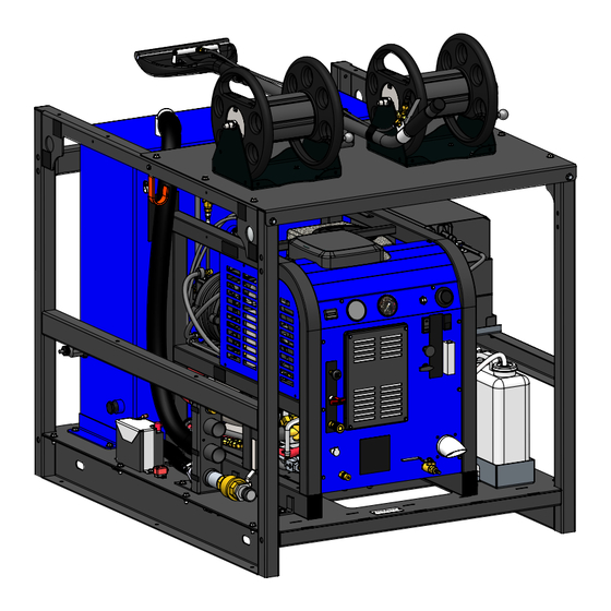
- Page 16 The HydraMaster Truckmount to Go is a mobile, high performance cleaning and extrac- tion system designed for restoration and cleaning contractors, facility managers, and disaster emergency response teams who need an easy to operate and easy to transport unit.
- Page 17 The unit is simply forklifted into the transport vehicle for delivery to the job site, or shipped by container or crate to the work site. HydraMaster is one of the largest manufacturers of truck mounted and high perfor- mance portable cleaning and extraction machines. For over 48 years, HydraMaster has innovated uncompromising deep cleaning, extraction and drying solutions.
-
Page 18: Machine Specifications
MACHINE SPECIFICATIONS Frame Dimensions 44”W x 45”H x 57”D Weight 1009 lbs (Empty Recovery Tank) 1529 lbs (Full Recovery Tank) Engine - 23HP Briggs Oil Type: 5W-30 Synthetic and Stratton air-cooled Capacity Approx. 1 1/2 quarts, or 48 oz. (when changing oil and filter) Engine RPM 3,150 RPM (no load) - Page 19 Standard Equipment Full Frame Enclosure Rain Guard, Full Steel Cage, Primer/Powder coated, vacuum hose hangers, tie down points Recovery Tank 70 Gallon Maxx-Air Universal Recovery Tank Cleaning Wand Evo 1-1/2 Wand Chemical Jug 2.5 Gallon Recovery Tank Pump Out Automatic Waste tank Dump System (AWDS) Remote Hose Connection Vacuum, AWDS, and recovery...
-
Page 20: High Altitude Operation
Contact the local Briggs and Stratton dealer or HydraMaster to obtain the proper jet size. Find your local Briggs and Stratton dealer at: http://www.vanguardengines.com/where-to-buy/dealer-locator/... - Page 21 Hard Water Area Map The hard water map, shown in Figure 1-1, defines hard water areas in the continental United States which compromise fluid related components such as hoses, fittings, heaters, pumps, valves and water-cooled engines. For other countries, hard water area maps can be obtained from geological societies.
- Page 22 Cleaning efficiency and equipment life is increased, chemical use decreased, and the appearance of cleaned carpets enhanced when water softeners are incorporated in hard water areas. HydraMaster strongly urges the use of water softener units with the TMTG 4000 in areas exceeding 3.0 grains per gallon.
- Page 23 Waste Water Disposal Advisory There are laws in most communities prohibiting the dumping of recovered “gray” water from carpet cleaning in any place but a sanitary treatment system. The cleaning rinse water, recovered into your unit’s vacuum tank, contains materials such as detergents, and must be safely processed before entering streams, rivers and reservoirs.
- Page 24 Filling Gas Tank The TMTG Truckmount to go is equipped with a 7 gallon fuel tank that is permanently mounted to the external frame. This tank complies with EPA and CARB SORE regulations. 1. Turn engine off and let cool for a minimum of 10 minutes before removing fuel cap 2.
- Page 25 2 - Transportation The unit and all accessories such as vacuum hoses and cleaning wands must be contained, immobilized, or secured so that they do not: • Leak • Spill • Blow off the vehicle • Fall from the vehicle •...
- Page 26 Use only securing devices specifically manufactured to attach or secure unit to a vehicle. A properly secured load must be able to withstand a minimum amount of force in each of the following directions. • Forwards Force = 80% of the cargo weight when braking while driving straight ahead.
-
Page 27: Cleaning And Chemicals
HydraMaster’s ClearWater Rinse™ has been formulated to protect vital components. HydraMaster will not warranty parts that have been damaged from using acid products that have obviously caused failures. 3-1: Cleaning Information... -
Page 28: Preparing The Carpet For Extraction
Relying on the rinse detergent to do the majority of the cleaning will result in overly long dry times and excess detergent residue left in the carpet. HydraMaster recommends the use of our pre-sprays: Fastbreak™ for residential carpet and Blitz™ for commercial carpet needs. -
Page 29: Overwetting
For more information about HydraMaster’s complete chemical product line, visit this web page: http://hydramaster.com/Products/Chemicals.aspx OVERWETTING Overwetting is an annoyance to all concerned. Extended drying times will leave the customer with a negative impression of both the cleaning company and the process used. -
Page 30: Cleaning Tool Tips
CLEANING TOOL TIPS Wands With a wand, keep cleaning strokes short, front to back, and run a “dry pass”. After pulling the wand for a strip of 3 or 4 ft. long with the solution trigger activated, go back up to the top of the stroke, and make a “dry “ pass [i.e. no solution flowing]. This gives the wand a second chance to pick up the solution on the carpet. - Page 31 3-5: Cleaning Information...
- Page 32 Only 8.8 lbs 2" Titanium Tube 16" Head 6 Stainless Steel Jets Item #000-163-054 16” ◂ 2” Titanium Truckmount Wand Only 6.8 lbs 1.5" Tube, 10" Head, Single Jet 10” Item #000-163-759 ◂ Evolution Stair Wand Cleaning Information: 3-6...
- Page 33 Only 6.8 lbs Item #000-163-058 2" Evolution Flood Wand 16” 3-7: Cleaning Information...
- Page 34 Rotary Tools HydraMaster’s selection of Rotary Extraction Tools includes the RX12 and the RX20 NEXT GEN. Evolution RX12 Hard Surface Cleaning Tool The Evolution RX12 can be used to clean tile, concrete and stone floors. Select the appropriate pre-spray and apply to the floor.
- Page 35 RX20 NEXT GEN Tool for Carpet, Hard Surface and Bonnet Cleaning Before turning on the RX20 NEXT GEN, adjust the handle; it should rest right below or even with the bottom of your pants’ front pockets, with the tool resting flat on the floor. Take your time in adjusting the tool’s height;...
- Page 36 Upholstery Tool - DriMaster 3 Use the upholstery tool on small rugs and furniture. When you clean rugs, be sure that the temperature and chemicals are safe for that particular type of rug. As with the larger tools, do not leave the surface of the upholstery too wet. Adjust the volume of water on the tool without it touching any surface: the water should just barely come out of the tool before the vacuum pulls it back in.
-
Page 37: Operating Instructions
4 - Operating Instructions This section describes how to operate the TMTG 4000, starting with a description of the dash assembly (see Figure 4-1). Vacuum Pressure Gauge Ignition Switch Gauge Temperature Hour Control Dial Meter Pump-In/Pump Clutch Switch Choke Auto Pump-Out Switch Throttle Figure 4-1. - Page 38 The lower dash houses the controls for: • Chemical system • Water box drain Chemical Metering Chemical System Valve Control Valve Chemical Flow Meter Solution Blower Lube Port Incoming Fresh Water Water Box Drain Figure 4-2. TMTG 4000 Lower Dash Assembly The lower dash assembly also houses the blower lube port and the solution out port where the wand/tool connects to the TMTG 4000 (see Figure 4-2).
-
Page 39: Start Up Procedure
START UP PROCEDURE Perform all daily periodic maintenance as specified in this Owner’s Manual. Connect a garden hose to supply water to the truckmount (see Figure 4-2). Toggle the “PUMP-IN SYSTEM” to “HP PUMP & PUMP-IN ON” Connect the cleaning wand or tool to the length of hose required to perform the cleaning job. - Page 40 12. Add appropriate chemical to the chemical jug, turn the “CHEMICAL SYSTEM” valve to the “PRIME” position to purge any air from the system (see Figure 4-3). Chemical Metering Control Knob Chemical Meter Chemical System Valve Figure 4-3. TMTG 4000 Chemical System Control and Metering With the truckmount running at full throttle, block off the vacuum intake to the recovery tank.
-
Page 41: Shut Down Procedure
Cap off the inlet(s) to the recovery tank. Spray a HydraMaster-recommended spray lubricant into the “BLOWER LUBE PORT” for about 5 to 7 seconds while the unit is running (see Figure 4-2). Allow machine to run additional 2 to 5 minutes under load to flush off lubricant. -
Page 42: Machine Maintenance
A maintenance log, provided in the Owner’s Manual, must be correctly and completely filled out. HydraMaster may request to inspect the logs before a warranty claim is honored. It is recommended that the log be affixed to the vehicle door near the truckmount for convenience and to serve as a maintenance reminder. -
Page 43: Operational Maintenance
• Inspect and clean the garden hose screen. • Inspect the truckmount for water and oil leaks, loose electrical connections, etc. and repair as needed. • Lubricate the blower through the lube port with a HydraMaster-recommended lubricant, P/N 000-087-006. Weekly Maintenance •... - Page 44 Quarterly Maintenance • Clean and gap the spark plugs to 0.030”. Replace if excessive carbon buildup is visible. • Check fuel filter. Replace as necessary. 100 Hours • Replace spark plugs every 100 hours. • Change the blower oil after first 100 hours of use. 250 Hours •...
-
Page 45: Overall Machine Maintenance
OVERALL MACHINE MAINTENANCE Maintenance, troubleshooting and repair are much easier tasks to accomplish on a clean truckmount. Regular cleaning of the truckmount offers the user an opportunity to visually inspect all facets of the truckmount and spot potential problems before they occur. In addition to the operational maintenance the following “housekeeping”... -
Page 46: Engine Maintenance
ENGINE MAINTENANCE Engine Oil Level Check The engine oil level should be checked daily. It is recommended that the oil be checked just before the engine is started for the first time for that day. The oil level should be between the ‘Add’... - Page 47 Engine Oil Recommendation While multi-viscosity oils are generally recommended, SAE 5W-30 synthetic is specifically recommended year round for your TMTG 4000 engine. Oil Filter Briggs and Stratton engines use Briggs and Stratton oil filters. An equivalent or better oil filter must be used when servicing the engine. To replace the filter, use a proper filter wrench to remove the filter.
-
Page 48: High Pressure Pump Maintenance
HIGH PRESSURE PUMP MAINTENANCE Daily Check the oil level and the condition of the oil. The oil level should be up to the center of the sight glass on the rear of the pump or between the “MIN” and “MAX” lines on the dipstick. - Page 49 Valve Maintenance (See Figure 5-1) Using a 22-mm wrench or socket, remove all six valve caps on the manifold of the pump. Examine each valve cap O-ring for cuts or distortions and replace if worn. Using needle nose pliers, remove the suction and delivery check valves. The valve assembly usually stays together when removing.
- Page 50 Replace old valves with new valves by placing the assembly in the valve chamber. Press down firmly on the top of the valve assembly. Replace valve caps by applying LOCTITE® 243 to valve cap and torque to 33 ft- lbs. Removing and Replacing Pump Manifold Remove the manifold of the pump by taking a 5-mm Allen head wrench and removing the eight head bolts.
- Page 51 Torque to 4.5 ft-lbs. Servicing the Crankcase While the manifold and plungers are removed, rotate the crankshaft by hand. Closely examine the crankcase oil seals for drying, cracking or leaking. Consult the local HydraMaster distributor if crankcase servicing is necessary. Machine Maintenance: 5-10...
-
Page 52: Vacuum System Maintenance
Cap off the inlet(s) to the recovery tank. Spray a HydraMaster-recommended spray lubricant into the “BLOWER LUBE PORT” for about 5 to 7 seconds while the unit is running. Allow machine to run additional 2 to 5 minutes under load to flush off lubricant. -
Page 53: Descaling Procedure (Required)
DESCALING PROCEDURE (REQUIRED) Scale deposits on the interior of the heating system can cause a noticeable loss in heating performance. Deposits of this kind result from hard water. The frequency with which descaling procedures are required will vary. If the area has particularly hard water, you may have to descale often. -
Page 54: Freeze Guarding
FREEZE GUARDING To avoid permanent damage to the truckmount, it is imperative to follow the Freeze Guard Procedure whenever the possibility of freezing temperatures exists. When disposing of antifreeze, follow local laws and regulations. Do not discard into storm sewers, septic systems or onto the ground. Antifreeze is harmful or fatal if swallowed. - Page 55 Freeze Guard Procedure With the truckmount turned off and the incoming water line disconnected, open the water box drain valve on the front of the truckmount. Allow the system to fully drain. Add 2 gallons of 50/50 antifreeze and water mix to the water box. Attach a section of solution hose to the outgoing solution fitting on the front of the machine.
- Page 56 To freeze guard the hoses and wand, perform the preceding procedure with the items to be freeze guarded attached. Always check the freezing level of your reclaimed antifreeze with a glycol tester before reusing. Failure to do so may result in serious component damage. Recovering Antifreeze for Re-Use Attach all hoses and wands which have been freeze guarded to the truckmount.
-
Page 57: Water And Chemical System
The water that is being called for by the wand then exits the manifold and passes through a check valve (see Figure 6-2). The chemical is pressurized by the HydraMaster diaphragm chemical pump attached to the head of the water pump. This pump pulls the chemical from the chemical or soap jug through the chemical flow meter (see Figure 6-3). - Page 58 Figure 6-1. Flow Diagram - View 1 of 3 000-179-038 Rev. A 6-3: Water and Chemical System...
- Page 59 Figure 6-2. Flow Diagram - View 2 of 3 000-179-038 Rev. A Water and Chemical System: 6-4...
- Page 60 Figure 6-3. Flow Diagram - View 3 of 3 000-179-038 Rev. A AWDS/DRAIN FLOW AWDS FLOAT SWITCH AWDS PUMP AWDS OUT 6-5: Water and Chemical System...
-
Page 61: Electrical System
7 - Electrical System This section describes how the electrical system functions in the following manner: „ Electrical System Information „ Electrical Schematic „ Wiring Diagram ELECTRICAL SYSTEM INFORMATION The TMTG 4000 electrical system operates on 12 V DC which is provided by the battery. - Page 62 REVISION DESCRIPTION CODE TEMPERATURE RELEASED DRAWING. SENSOR REPLACED APO WIRING WITH AWDS; MOVED THE VOLTAGE REGULATOR WIRE FROM INGNITION ECR# 2808 COLOR KEY SW-6 SWITCH (SW-1) TO STARTER SOLENOID (SOL-1); ECR# 2677 UPDATED VACUUM TANK HIGH WATER FLOAT BLACK - DENOTES WIRES (FS-2) TO BE CONNECTED TO TB2-1, TB2-2, TB2-5.
- Page 63 COLOR KEY Figure 7-2. Wiring Diagram - BLACK - DENOTES WIRES RED - DENOTES OPTIONAL EQUIPMENT View 1 of 3 GREEN - DENOTES COMPONENTS 000-179-047 Rev. C THERMOSTAT IGNITION SWITCH TS-1 [TO ENGINE GROUND] 17(WHT/ORG) SW-1 20(BLK/WHT) HOUR METER HI-1 38(BLU/WHT) 20(BLK/WHT) 24(PNK)
- Page 64 23(PNK/WHT) 23(PNK/WHT) 25(PNK) [TO IGNITION SWITCH SW-1 #2] 03(YEL) P-10 J-10 (ORG) 35(ORG) [TO IGNITION SW-1 #5 - 16 GA.] FUSE FUSE 06(ORG) 14 GA Figure 7-3. Wiring FU-1 FU-1 19(BLK) P-11 J-11 P-13 J-13 (ORG) 34(BLK) [TO APO SWITCH SW-3 #3 - 14 GA.] 25 A 25 A FUSE...
-
Page 65: Systems Troubleshooting
8 - Systems Troubleshooting This section describes the standard troubleshooting procedures in the following areas: „ Heating System „ Chemical System „ Engine „ High Pressure System „ Vacuum System 8-1: Systems Troubleshooting... -
Page 66: Heating System
HEATING SYSTEM 1.0 Truckmount overheats and shuts down Possible Cause Solution 1.1 The orifice or filter screen Remove and inspect. Clean as necessary. is restricted. 1.2 The dump solenoid is Inspect the solenoid and the hose that delivers restricted. water to it. Clean or replace as necessary. 1.3 The dump solenoid is Check the main fuse. -
Page 67: Chemical System
CHEMICAL SYSTEM 1.0 System will not prime Possible Cause Solution 1.1 The check valves in Remove the valves and inspect. Clean or replace as chemical pump are faulty. necessary. 1.2 The chemical pump Remove and inspect. Replace as necessary. diaphragm is faulty. 1.3 The check valve in high Remove the valve and inspect. -
Page 68: Engine
ENGINE 1.0 Will not turn over Possible Cause Solution 1.1 A loose or corroded Clean and tighten the battery terminal connections. battery terminal. 1.2 The battery is dead. Recharge or replace the battery. Test the charging system. Repair if necessary. Do not attempt to jump start the truckmount from a running vehicle. - Page 69 2.0 Turns over but will not start; there is no spark. (To check for spark, refer to engine manual.) Possible Cause Solution 2.1 The recovery tank is full. Drain the tank. 2.2 The recovery tank float is Inspect the float. Repair or replace as necessary. faulty.
- Page 70 4.0 Will not come up to normal operating rpm. Note: engine should be adjusted to run at 3,200 rpm under no vacuum load. Possible Cause Solution 4.1 The throttle linkage is out Inspect for broken or loose linkage. Repair or replace of adjustment.
- Page 71 7.0 Engine overheats Possible Cause Solution 7.1 Poor ventilation in the van. Open all the van doors. Install a roof vent in the van. Remove any dividers or other objects impeding airflow around the truckmount. 7.2 Low oil level. Check the level and fill as necessary. Running the engine with a low oil level can cause severe damage to the engine.
-
Page 72: High Pressure System
HIGH PRESSURE SYSTEM 1.0 The pump will not come up to normal cleaning pressure Possible Cause Solution 1.1 The pressure adjusting Inspect the valve. Repair or replace if necessary. valve is faulty. 1.2 Worn seals or valves in Test the pump output volume directly from the pump the pump. - Page 73 4.0 Pressure pulsation Possible Cause Solution 4.1 Air leak between the water Check all the hoses and fittings for cuts, breaks, box and pump. cracks, etc. Repair as necessary. 4.2 The check valve(s) in the Remove each valve and inspect for correct pump are faulty.
-
Page 74: Vacuum System
VACUUM SYSTEM 1.0 A weak vacuum at wand. The gauge reads normal. Possible Cause Solution 1.1 Blockage in the hoses or Disconnect the hoses and check for an obstruction. wand tube 1.2 Excessive length of Do not attach excessive lengths of hose. hose connected to the truckmount 2.0 A weak vacuum... - Page 75 5.0 The vacuum blower is locked and will not turn Possible Cause Solution 5.1 Truckmount has been Spray penetrating oil into the blower and let sit for inactive for a period of at least 1 hour. Then very carefully use pipe wrench time and the blower was on the outer diameter of the pulley on the coupler not properly lubricated...
-
Page 76: Assemblies And Parts Lists
9 - Assemblies and Parts Lists This section of the manual provides detailed illustrations and parts lists for the following assemblies. When ordering parts for assemblies, first refer to the appropriate assembly listed here and then find the part number listed on that specific page. In most cases, you do not have to order the entire assembly to get a part. - Page 77 HydraMaster equipment. Refer to Figure 9-1 to identify those substances such as A1, A2 and so forth. Equivalent products are acceptable if they meet or exceed current specifications and are approved by HydraMaster. Figure 9-1. Adhesive/Sealant Material Reference...
- Page 78 Figure 9-2. Truckmount to Go 4000 - View 1 of 6 750-013-756-10 Rev. A 000-081-509 LABEL, DO NOT LIFT 000-081-508 LABEL, TIE DOWN LOCATION 9-3: Assemblies and Parts Lists...
- Page 79 Figure 9-3. Truckmount to Go 4000 - View 2 of 6 750-013-756-10 Rev. A 61.040 46.750 57.000 44.000 NOTES: 1. ITEM NOT SHOWN. 2. PART OF LABEL SET #0 9-4: Assemblies and Parts Lists...
- Page 80 Figure 9-4. Truckmount to Go 4000 - View 3 of 6 750-013-756-10 Rev. A RELEASE D 000-081-509 LABEL, DO NOT LIFT 000-081-508 WASHER, 5 LABEL, TIE DOWN WASHER, 3 LOCATION WASHER, 1 WASHER, 1 WASHER, 0 WASHER, # WAND 1.5" TRAY, SOA TANK, 7 GA SWITCH, F...
- Page 81 Figure 9-5. Truckmount to Go 4000 - View 4 of 6 750-013-756-10 Rev. A DETAIL A SCALE 1 : 4 9-6: Assemblies and Parts Lists...
- Page 82 Figure 9-6. Truckmount to Go 4000 - View 5 of 6 750-013-756-10 Rev. A REVISIONS DESCRIPTION CODE DATE CHKD APPVD RELEASE DRAWING. 06/06/2019 L.O.L. L.R.K. L.R.K. 000-081-509 LABEL, DO NOT LIFT 000-081-508 WASHER, 5/16" FLAT 18-8 S. STEEL 000-174-049 LABEL, TIE DOWN WASHER, 3/8"...
- Page 83 DETAIL A SCALE 1 : 4 Figure 9-7. Truckmount to Go 4000 - View 6 of 6 750-013-756-10 Rev. A DETAIL B SCALE 1 : 4 9-8: Assemblies and Parts Lists PROPRIETARY INFORMATION 11015 47th Avenue West, Mukilteo, Washington 98275...
-
Page 84: Truckmount To Go 4000 Parts List
Truckmount to Go 4000 - Parts List Item Part Number Description Item Part Number Description 000-163-603G ASSEMBLY, 14” HOSE REEL - GARDEN 000-068-035 HOSE, 5/8” x 50’ GARDEN 610-003-756 ASSEMBLY, 70 GALLON URT - E10 000-052-098 INSERT, #25 610-050-756 ASSEMBLY, CONSOLE - TMTG 4000 000-052-096 INSERT, #F23 (1/8”... -
Page 85: Truckmount To Go 4000 Console Parts List
Truckmount to Go 4000 - Parts List (continued) Item Part Number Description Item Part Number Description 000-143-242 SCREW, 5/16”-18UNC x 0.75” LG. HEX HEAD G. 5 000-163-034 WAND 1.5” ALUMINUM 000-143-013 SCREW, 5/16”-18UNC x 1.00” LG. HEX HEAD G. 8 000-174-001 WASHER, #10 FLAT 000-143-012... - Page 86 Figure 9-8. Truckmount to Go 4000 Console- View 1 of 3 610-050-756 Rev. A REVISION DESCRIPTION CODE DATE CHKD APPVD RELEASE DRAWING. 06/05/2019 L.O.L. L.R.K. L.R.K. WASHER, #10 LOCK S. STEEL 000-174-014 WASHER, #10 FLAT S. STEEL 000-174-001 SCREW, #10-24UNC x 0.50" LG. HEX HEAD S.
- Page 87 Figure 9-9. Truckmount to Go 4000 Console - View 2 of 3 610-050-756 Rev. A PART OF FRAME HIDDEN FOR CLARITY 9-12: Assemblies and Parts Lists PROPRIETARY INFORMATION 11015 47th Avenue West, Mukilteo, Washington 98275...
- Page 88 Figure 9-10. Truckmount to Go 4000 Console - View 3 of 3 610-050-756 Rev. A 3.126 35.125 24.000 31.937 30.940 PROPRIETARY INFORMATION 11015 47th Avenue West, 28.000 Mukilteo, Washington 98275 ASSEMBLY, CONSOLE - TMTG 4000 9-13: Assemblies and Parts Lists DRAWN L.O.L.
- Page 89 Truckmount to Go 4000 Consule - Parts List Item Part Number Description Item Part Number Description 610-002-755 ASSEMBLY, BLOWER - TMTG 000-068-517 HOSE, 3/16” I.D. TEFLON x 23” (CHEM PUMP TO 610-018-756 ASSEMBLY, DASH - TMTG E10 PRIME & CHEM METERING TO SOL OUT) 610-007-737 ASSEMBLY, 318 RESTORATION PUMP 000-068-888...
- Page 90 REMOVED & NOTATED 081-408 & 081-327; ECR #2464 11/15/2013 S.M.W. C.I.R. ECRB UPDATED NOTE 1; 055-195 WAS REVISED E MOVED 105-012 & 140-001 TO CONSOLE. ECR #2520 05/15/2014 L.O.L. C.I.R. ECRB Figure 9-11. Frame Assembly - View 1 of 2 610-001-729 Rev.
-
Page 91: Frame Assembly Parts List
000-081-327 LABEL, ANSI WARNING TEXT ONLY Figure 9-12. Frame Assembly - View 2 of 2 610-001-729 Rev. E 000-081-408, CLEAN FILTERS DAILY, HORIZONTAL Frame Assembly - Parts List (continued) Item Part Number Description Item Part Number Description 610-021-009 ASSEMBLY, IDLER PULLEY 000-056-011 FUSE, 30 AMP 610-021-724... - Page 92 Figure 9-13. Blower Assembly - View 1 of 2 610-002-755 Rev. A See Figure 9-1 for adhesive/sealant information. MOVE BOTH VENTS TO THIS SIDE 000-027-112 0.75±0.25 CAP, OIL SIGHT GLASS 0.188±0.125 TORQUE TO 40 FT LBS 0.75±0.25 000-027-112 CAP, OIL SIGHT GLASS TORQUE TO 40 FT LBS 9-17: Assemblies and Parts Lists...
- Page 93 Figure 9-14. Blower Assembly - View 2 of 2 610-002-755 Rev. A BLOWER REVISION DESCRIPTION CODE DATE CHKD APPVD See Figure 9-1 for sealant information. RELEASE DRAWING. 05/23/2019 L.O.L. L.R.K. L.R.K. 000-027-112 0.75±0.25 CAP, OIL SIGHT GLASS TORQUE TO 30 FT LBS COUPLER 0.188±0.125 TORQUE TO...
-
Page 94: Blower Assembly Parts List
Blower Assembly Parts List Item Part Number Description Item Part Number Description 000-001-871 ADAPTER BLOWER OUTLET 2.5 - COATED 000-077-011 KEY, 3/16” X 1 1/2” LONG 000-094-015 NUT, 3/8”-16UNC HEX 2 WAY LOCKING 000-001-219 ADAPTER, BLOWER INLET - COATED 000-111-145 BLOWER, 4005 DOMINATOR 000-143-141 SCREW, 1/4”-20UNC x 0.50”... - Page 95 REVISIONS DESCRIPTION CODE DATE CHKD APPVD NEW DRAWING 04/02/2015 C.I.R. L.O.L. ECRB REPLACED 1 QTY. 610-009-729 WITH 610-009-747. 11/16/2016 L.O.L. ECRB ECR #2742 Figure 9-15. Pump Assembly 610-007-737 Rev. B 000-143-580 SCREW, M5 X 0.8 X 6MM SET CUP POINT COMES WITH See Figure 9-1 for adhesive/sealant information.
-
Page 96: Pump Assembly Parts List
Pump Assembly Parts List Item Part Number Description Item Part Number Description 000-001-096 ADAPTER, CHEM. PUMP TO COMET 000-094-038 NUT, 5/16”-18UNC HEX NYLOCK 610-009-747 ASSEMBLY, BY-PASS VALVE 000-097-057 O-RING, ADAPTER - CHEMICAL PUMP 000-036-008 CLUTCH, 7” O.D. 24mm SINGLE GROOVE 000-105-148 PLATE, CLUTCH MOUNT COMET PUMP 000-052-084... - Page 97 Figure 9-16. Dash Assembly - View 1 of 2 610-018-756 Rev. A 000-157-017 SWITCH, IGNITION B&S COMES WITH 000-047-028 See Figure 9-1 for adhesive/sealant information. 000-081-410 LABEL, THERMOSTAT 000-081-331 LABEL, TEMPERATURE 000-081-405 LABEL, DASH CONTROL - LEFT 000-081-416 LABEL, DASH RESTORATION - RIGHT KNOB, CHEMICAL SELECTOR COMES WITH 39 000-081-328...
- Page 98 INSERT, #66 (3/8" NPT x 3/8" BARB) BRASS 000-0 INSERT, #26 (1/8" NPT x 3/8" BARB) BRASS 000-0 GAUGE, 30" HG. VACUUM - HYDRAMASTER VARIOUS 000-0 GAUGE, PRESSURE 0 -1500 PSI, UPC #401406. VARIOUS 000-0 ELBOW, 1/8" NPT x 1/4" SAE...
-
Page 99: Dash Assembly Parts List
SWITCH, 3 WAY SPEED CONTROL 000-074-007 GAUGE, PRESSURE 0 -1500 PSI, UPC #401406. 000-052-090 TEE, 1/4” NPT BRANCH M-F-F 000-074-017 GAUGE, 30” HG. VACUUM - HYDRAMASTER 000-149-025 THERMOSTAT, BULB & CAPILLARY 000-052-099 INSERT, #26 (1/8” NPT x 3/8” BARB) 000-131-131 TRIMLOK, 3/8”... -
Page 100: Differential Check Valve Assembly Parts List
Figure 9-18. Differential Check Valve Assembly 000-169-236 Rev. B Differential Check Valve Assembly Parts List Item Part Number Description Item Part Number Description 000-097-054 O-Ring, Chem. Pump Valve Viton-Parker 2-114 000-005-012 Ball, 0.500 Dia Stainless Steel 000-148-012 Seat, Differential Check Valve 000-107-258 Body, Differential Check Valve 000-106-180... -
Page 101: By-Pass Valve Assembly Parts List
REVISION DESCRIPTION CODE DATE CHKD APPVD DRAWING RELEASED. 10/8/2015 L.O.L. C.I.R. C.I.R. ITEM 3 WAS 052-528 02/02/2016 C.I.R. L.O.L. C.I.R. LRIP Figure 9-19. By-Pass Valve Assembly 610-009-747 Rev. B VALVE, PRESSURE REGULATOR-MODIFIED VARIOUS 000-169-351 By-Pass Valve Assembly Parts List TEE, 3/8" NPT MALE BRANCH BRASS 000-052-447 PLUG, 3/8"... -
Page 102: Orifice Assembly Parts List
Figure 9-20. Orifice Assembly 610-021-729 Rev. A REVISIONS REVISION CODE DATE CHKD Orifice Assembly Parts List Item Part Number Description Item Part Number Description 000-052-084 ELBOW, 1/8” NPT STREET 000-052-582 NIPPLE, TEE JET STYLE COLLAR X 1/8” NPT TEE, 1/8" FPT BRASS 000-094-028 NUT, BRASS JET ASSEMBLY... - Page 103 Figure 9-21. Engine Assembly - View 1 of 2 610-004-728 Rev. E See Figure 9-1 for adhesive/sealant information. 9-28: Assemblies and Parts Lists...
-
Page 104: Engine Assembly Parts List
Figure 9-22. Engine Assembly - View 2 of 2 610-004-728 Rev. E Engine Assembly Parts List Item Part Number Description 000-020-025 Bushing, H X 1” 000-033-117 Clamp, 1” Cushion Loop w/ 7/16 Mount Hole 000-039-054 Coupler, 40 Series 000-047-037 Engine, 23HP 000-049-258 Filter, Fuel (Comes w/ Engine) 000-057-026... - Page 105 Figure 9-23. Blower Heat Exchanger Assembly RELE 610-005-754 Rev. A SENSOR (COMES WITH 000-149-025) See Figure 9-1 for sealant information. 9-30: Assemblies and Parts Lists TEE, NIPP NIPP NIPP...
-
Page 106: Blower Heat Exchanger Assembly Parts List
Blower Heat Exchanger Assembly Parts List Item Part Number Description Item Part Number Description 000-057-255 GASKET, SALSA HX - CDS ZR-2017 000-052-738 ADAPTER, 1/4” NPT x 1/2” FPT 000-068-986 HOSE, 2.5” HEAT FLEX NS x 15” LG. 000-013-115 BOX, OUTLET PLENUM, STEEL - COATED 000-052-528 NIPPLE, 3/8”... -
Page 107: Idler Pulley Assembly Parts List
REVISION DESCRIPTION CODE DATE CHKD APPVD 000-154-049 WAS 000-154-128. 12/4/2012 L.O.L. K.W. K.W. LRIP REPLACED 000-143-041 WITH 000-143-716. ECR #2635 03/11/2016 C.I.R. ECRB UPDATED TITLE BLOCK. Figure 9-24. Idler Pulley Assembly 610-021-009 Rev. C WASHER, 1/4" FLAT S/S S. STEEL 000-174-003 WASHER, 1/2 SAE H/D STEEL... -
Page 108: Silencer Assembly Parts List
REVISIONS REVISION CODE DATE CHKD APPVD A ITEM 2 WAS 068-780; LRIP 2/12/2008 L.O.L. B.R.T. B.R.T. B UPDATED TITLE BLOCK 7/5/2011 Figure 9-25. Silencer Assembly Silencer Assembly Parts List 610-021-724 Rev. A Item Part Number Description 000-033-012 CLAMP, SIZE #44 HOSE 000-068-104 HOSE, Ø2.5”... - Page 109 Figure 9-26. Water Box Assembly 610-010-725 Rev. H See Figure 9-1 for adhesive and NOT THE ACTUAL LENGTH OF THE HOSE. USE A 13/16" DRILL BIT TO ROUTE THE sealant information. OVERFLOW HOSE TO THROUGH THE VAN'S FLOOR. 9-34: Assemblies and Parts Lists NOTES: 1.
-
Page 110: Water Box Assembly Parts List
Water Box Assembly Parts List Item Part Number Description Item Part Number Description 000-169-235 ASSEMBLY, ROBERT FLOAT VALVE 000-094-097 NUT, 1”-14UNS BRASS 000-097-041 O-RING, 1/2” BULK HEAD 000-052-660 BULKHEAD, 3/8” FPT x 3/8” FPT 000-033-003 CLAMP, SIZE #4 MINI HOSE 000-143-017-1 SCREW, 3/8”-16UNC x 0.75”... - Page 111 REVISION DESCRIPTION CODE DATE CHKD APPVD RELEASE DRAWING 2/9/2018 L.O.L. M.B.B. M.B.B. ADD 057-199; DELETE 057-177 & 125-128. 03/23/2018 M.B.B. L.O.L. L.O.L. LRIP Figure 9-27. Exhaust Manifold Assembly 610-013-754 Rev. B Exhaust Manifold Assembly Parts List Item Part Number Description NOTES: 1.
- Page 112 REVISION DESCRIPTION CODE DATE CHKD APPVD RELEASE DRAWING. 6/5/2019 L.O.L. L.R.K. L.R.K. REVISION DESCRI Figure 9-28. 70 Gallon Universal Recovery Tank Assembly RELEASE DRAWING. 610-003-756 Rev. A DETAIL VIEW A WASHER, 3/8" FLAT RUBBER BA WASHER, 1/4" LOCK S/S WASHER, 1/4" FLAT S/S WASHER, #10 FLAT WASHER, #10 FLAT RUBBER BA VALVE, 12 VOLT SOLENOID 120...
-
Page 113: Gallon Universal Recovery Tank (Urt) Assembly Parts List
70 Gallon Universal Recovery Tank Assembly Parts List Item Part Number Description Item Part Number Description 000-001-134 ADAPTER, Ø2.5” TANK x 90° BLOWER HOSE 000-094-009 NUT, 1/4”-20UNC NYLOCK 000-106-049 PLUG, 1” NPT BLACK NYLON 610-029-756 ASSEMBLY, COVER, 70 GAL URT, SINGLE VAC. - E10 1 610-026-724 ASSEMBLY, VACUUM RELIEF VALVE - URT 000-106-019... - Page 114 REVISION DESCRIPTION CODE DATE CHKD APPVD RELEASE DRAWING. 06/05/2019 L.O.L. L.R.K. L.R.K. Figure 9-29. 70 Gallon Universal Recovery Tank (URT) Cover Assembly 610-029-756 Rev. A PART OF 086-008 ON RECOVERY TANK ASSEMLY SCREW, #6-32UNC x 0.50" LG. BUTTON HEAD 18-8 S. STEEL 000-143-539 NUT, #6-32UNC HEX NYLOCK S.
-
Page 115: Gallon Universal Recovery Tank (Urt) Cover Assembly Parts List
70 Gallon Universal Recovery Tank (URT) Cover Assembly Parts List Item Part Number Description Item Part Number Description 000-052-219 ADAPTER, 2” NPT x 2” F SLIP 000-057-203 GASKET, MIDDLE - REC. TANK COVER 000-057-204 GASKET, SIDE - RECOVERY TANK 000-041-443 COVER, 70 URT 1 PORT - COATED E10 000-052-222 ELBOW, 2”... -
Page 116: 14" Hose Reel - Garden Assembly Parts List
Figure 9-30. 14” Hose Reel - Garden Assembly 000-163-603G Rev. G REVISION DESCRIPTION CODE DATE CHKD APPVD REMOVED 1 QTY. 000-052-061, 2 QTY. 000-052-085, 1 QTY. 000-052-082, 1 QTY. 000-052-678, 1 QTY. 000- 5/12/2017 P.E. R.D.D. ECRB ECR #2755 052-052. ROLL REV TO RE-ACTIVATE IN LN. -
Page 117: Vacuum Relief Valve Assembly Parts List
Figure 9-31. Vacuum Relief Valve Assembly 610-026-724 Rev. B Vacuum Relief Valve Assembly Parts List Item Part Number Description Item Part Number Description 000-015-182 Bracket, Vacuum Relief Valve - Fabricated 000-105-332 Plate, Vacuum Relief Valve Mounting - Coated 000-143-198 Screw, 3/8”-16UNC X 4” Lg. Hex Head - Full Thread 000-027-032 Cap, Spun Vacuum Relief Valve 000-094-101... -
Page 118: Dump/Vacuum Bracket -Tmtg Assembly Parts List
REVISION DESCRIPTION Figure 9-32. Dump / Vacuum Bracket - TMTG Assembly RELEASE DRAWING. 610-019-755 Rev. A WASHER, 3/8" FLAT AISI 304 000-174-032 WASHER, 1.5" O.D. x 1.073" I.D. x 0.075" THK. S. STEEL 000-174-063 WASHER, 1" FLAT S. STEEL 000-174-050 VALVE, 3/4"... -
Page 119: How To Order Parts
We shall always endeavor to be fair in our evaluation of your warranty claim and shall provide you with a complete analysis of our findings. HydraMaster warranty covers only defective materials and/or workmanship for the periods listed. Diagnostic reimbursement is specifically excluded. -
Page 120: Warranty Information
Such causes listed in this section shall constitute abuse or neglect. BLOWER • Failure to lubricate impellers daily with a HydraMaster-recommended lubricant, to lubricate bearings, to maintain proper oil levels, or to use the correct oil grade and viscosity as recommended in blower manual. -
Page 121: Vacuum And Solution Hoses
Warranty coverage is available to you through your local distributor. If you have moved to a new area or have purchased a used machine and need information regarding your local distributor, call HydraMaster at (800) 426-1301 or email us at: techsupport@hydramaster.com. - Page 122 All material must be properly authorized by HydraMaster prior to being returned. When returning, please provide an explanation of the problem and include the serial number of the machine as well as the name of the selling organization. All defective material must be returned to HydraMaster within 60 days of authorization.
-
Page 123: Accessories And Chemical Solutions
12 - Accessories and Chemical Solutions HydraMaster’s machine accessories are the most innovative collection available in the cleaning industry. For example, our RX20® has changed the shape of steam cleaning. In addition, our hoses, reels and tanks are of the finest quality construction.
Need help?
Do you have a question about the Truckmount to Go TMTG 4000 and is the answer not in the manual?
Questions and answers