
Related Manuals for Woodward ProTech 203


Summary of Contents for Woodward ProTech 203
- Page 1 Installation and Operation Manual ® ProTech Overspeed Protection System 9907-146, -147, -148, -149, -150, -151 Manual 85204 (Revision G)
- Page 2 Revisions—Text changes are indicated by a black line alongside the text. Woodward Governor Company reserves the right to update any portion of this publication at any time. Information provided by Woodward Governor Company is believed to be correct and reliable. However, no responsibility is assumed by Woodward Governor Company unless otherwise expressly undertaken.
-
Page 3: Table Of Contents
Power Supply Description ..................11 4. C .......... 13 HAPTER ONFIGURATION AND PERATION Programming ......................15 ProTech 203 Programming Worksheet ..............16 Operation ......................17 5. T ........ 21 HAPTER ROUBLESHOOTING AND EPAIRS Troubleshooting ....................21 ... - Page 4 Figure 3-2. Interposing Relay Field Wiring ............10 Figure 3-3. Voter Relay Configuration ..............11 Figure 3-4. Block Diagram of One Unit of the ProTech 203 System ....12 Figure 4-1. ProTech 203 Front Panel ..............13 ...
-
Page 5: Electrostatic Discharge Awareness
PCB from the control cabinet, place it in the antistatic protective bag. To prevent damage to electronic components caused by improper handling, read and observe the precautions in Woodward manual 82715, Guide for Handling and Protection of Electronic Controls, Printed Circuit Boards, and Modules. -
Page 6: Regulatory Compliance
Manual 85204 Regulatory Compliance The ProTech 203 is suitable for use in Class I, Division 2, Groups A, B, C, and D per UL for Canada and US or non-hazardous locations only. The ProTech 203 is suitable for use in European Zone 2, Group II environments per compliance with EN60079-15, Electrical apparatus for explosive atmospheres –... -
Page 7: Chapter 1. General Information
ProTech 203 system, read manual 82715, Guide for Handling and Protection: Electronic Controls, Printed Circuit Boards, Modules. Description The ProTech 203 Overspeed Protection System is a digital overspeed trip device that senses prime mover speed through three magnetic pickups (MPUs). It consists of three identical, independent, speed-sensing units which continuously monitor prime mover speed and activate a trip relay when an overspeed condition is detected. -
Page 8: References
120 Vac/dc = 88–132 Vac, 12.5 VA 90–150Vdc, 4.77 W 220 Vac = 180–264 Vac, 16.4 VA References The following Woodward publications contain additional product or installation information on overspeed protection systems and related components. 82715 Guide for Handling and Protection: Electronic Controls, Printed... -
Page 9: Chapter 2. Installation
Power Requirements The ProTech 203 system can be configured to operate with numerous power sources. Each unit contains an independent power supply module that can be ordered in the configurations described in Tables 1-1, 1-2, and 1-3 in Chapter 1. -
Page 10: Plant Wiring
Woodward for more information. Plant Wiring Figure 2-1 is the plant wiring diagram for the ProTech 203 system. Figure 2-2 shows the proper routing and stress relief for all field wiring entering the ProTech system. Field wiring to the ProTech system should be between 1.5 and 6 mm²... -
Page 11: Figure 2-1. Plant Wiring Diagram
Actuating equipment integration assessment: Woodward strongly recommends that the user perform an assessment of the actuating equipment that will receive input from the ProTech 203 system to verify that equipment is properly calibrated, working correctly, properly interfaced, and functioning safely before energizing the ProTech 203 system. -
Page 12: Figure 2-2. Routing And Stress Relief For Field Wiring Entering The Protech 203 System
ProTech 203 Overspeed Protection System Manual 85204 Figure 2-2. Routing and Stress Relief for Field Wiring Entering the ProTech 203 System Woodward... -
Page 13: Chapter 3. Description
See Figure 3-1 for the control layout and dimensions. Figure 3-1. Outline Drawing of ProTech 203 System Specifications Enclosure Approved for use in Type 4 and 4x environments for North America. Enclosure rated IP54 for Europe. - Page 14 ProTech 203 Overspeed Protection System Manual 85204 Remote Reset Can be reset from a remote location The external field wiring to the Remote Reset and Contact Input terminals must be protected from user accessibility. It must be hard- wired like a hazardous voltage circuit.
- Page 15 Manual 85204 ProTech 203 Overspeed Protection System Shutdown Contact Ratings European Ratings European ratings restrict use to applications with voltages not subject to the Low Voltage Directive (73/23/EEC). Rated Voltage Resistive Inductive Tungsten Motor 28 Vdc 10.0 A 1.0 A 3.0 A...
-
Page 16: Modes Of Operation
4 and 5 are connected. During an overspeed trip event, or when power to the ProTech 203 system is lost, the interposing relay is de-energized. Then TB3 terminals 2 and 3 are connected, and TB2 terminals 5 and 6 are connected. -
Page 17: Power Supply Description
PROGRAM mode, preventing unauthorized changes. Power Supply Description The ProTech 203 consists of three units (A, B, and C). Each unit has its own separate power supply. There are three different versions of power supplies which have the following input voltages: 18–32 Vdc, 90–150 Vdc/88–132Vac, and 180–264 Vac. -
Page 18: Figure 3-4. Block Diagram Of One Unit Of The Protech 203 System
ProTech 203 Overspeed Protection System Manual 85204 Figure 3-4. Block Diagram of One Unit of the ProTech 203 System Woodward... -
Page 19: Chapter 4. Configuration And Operation
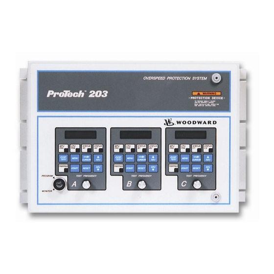
Manual 85204 ProTech 203 Overspeed Protection System Chapter 4. Configuration and Operation Figure 4-1. ProTech 203 Front Panel ® The ProTech 203 system can be operated in one of two modes, MONITOR or PROGRAM. Although the system will "run" in either mode, it is recommended that the unit be placed in the PROGRAM mode only during configuration and then placed in the MONITOR mode during normal operation. - Page 20 ProTech 203 Overspeed Protection System Manual 85204 PRESENT SPEED is the first parameter displayed. Each subsequent press of the menu key displays the next parameter in the list. Appropriate descriptive units for each parameter are also displayed. When the keyswitch is in the MONITOR position, the CURSOR RIGHT, ADJ UP, and ADJ DOWN keys have no effect.
-
Page 21: Programming
Manual 85204 ProTech 203 Overspeed Protection System Programming Programming of the ProTech 203 system consists of entering values for all the tunable parameters. The procedure for programming each speed-sensing unit is as follows: In order to ensure proper functioning of the ProTech 203 system, it is imperative that the tunable parameters in each of the units are programmed to result in identical trip points. -
Page 22: Protech 203 Programming Worksheet
ProTech 203 Overspeed Protection System Manual 85204 17. Return the keyswitch to the monitor position. The LCD displays CHANGES SAVED for two seconds. For your convenience, a programming worksheet is provided below. The worksheet should help ensure proper programming and provide you with a hard copy record of the values entered. -
Page 23: Operation
Start-up The ProTech 203 system allows two methods for turbine start. The "TIMER STARTS ON RESET" menu option determines which method is used. The default setting for this option is "NO", which provides separate reset and start functions. -
Page 24: Figure 4-3. Method 2 Block Diagram
ProTech 203 Overspeed Protection System Manual 85204 If the unit is being restarted after a normal rolldown (that is, there was no trip), the unit does not require a reset. The MPU fail trip is overridden because the MPU fail timer is cleared whenever speed exceeds the MPU fail set point. The MPU fail timer should be started by the operator when the turbine is ready to be started again. - Page 25 Manual 85204 ProTech 203 Overspeed Protection System When the "TIMER STARTS ON RESET" option is set to "YES", the "ALM IF SPD < MPU FAIL SETPT" option is active. If "ALM IF SPD < MPU FAIL SETPT" option is set to "YES", the alarm relay de-energizes whenever speed is below the MPU fail set point.
- Page 26 ProTech 203 Overspeed Protection System Manual 85204 Overspeed Test The overspeed test function is activated when the keyswitch is in the PROGRAM position and the operator presses and holds the OVSP TEST button on the touchpad. The microcontroller switches the source of the MPU signal from the MPU input to an on-board oscillator.
-
Page 27: Chapter 5. Troubleshooting And User Repairs
Manual 85204 ProTech 203 Overspeed Protection System Chapter 5. Troubleshooting and User Repairs Troubleshooting ® The following troubleshooting guide will help isolate problems in the ProTech 203 device, actuating system, plant wiring, MPUs, or elsewhere. Make the checks in the order indicated. - Page 28 ProTech 203 Overspeed Protection System Manual 85204 Symptom Cause Remedy Inappropriate trip Contact input was left open If contact input is not used, during start-up and TIMER STARTS ON jumper together TB5-14 and RESET option is set to "Yes" TB5-15 of each unit.
-
Page 29: User Repairs
Manual 85204 ProTech 203 Overspeed Protection System User Repairs The ProTech device is highly reliable and should require minimal hardware repairs. Use the above troubleshooting guide to determine the course of action if a problem does occur. In some cases, you will need to return the ProTech system to the supplier from whom your purchased it. -
Page 30: Figure 5-1. Protech System Front Door
ProTech 203 Overspeed Protection System Manual 85204 Figure 5-1. ProTech System Front Door If you're replacing a fuse in Unit A, remove the ribbon-cable clamp and retain for use when re-installing the cover (Figure 5-2). Figure 5-2. Unit Covers Inside the ProTech Device Unplug the power supply board terminal block, then unplug the I/O board terminal block (Figure 5-2). - Page 31 Manual 85204 ProTech 203 Overspeed Protection System Remove the fuses and examine them for defects. Replace any defective or suspect fuse. Replace the unit's cover and snugly secure the four nuts that hold the cover in place. If you've been working on Unit A, replace the ribbon-cable clamp onto the cover (Figure 5-2).
-
Page 32: Figure 5-3. Board Locations
ProTech 203 Overspeed Protection System Manual 85204 Unscrew the four long screws holding the two-board pack together (Figure 5-3). Figure 5-3. Board Locations Remove the six mounting screws securing the power supply board to the chassis. Unplug the ribbon cables from the power supply board, and remove the board. -
Page 33: Figure 5-4. Display Boards
Manual 85204 ProTech 203 Overspeed Protection System Figure 5-4. Display Boards Procedure to Install a New Unit Insert and position the new display board in place (Figure 5-4). Replace the six display board nuts, tighten until they are snug (if replacing unit A, re-install the ribbon-cable clamps). -
Page 34: Chapter 6. Service Options
A Recognized Turbine Retrofitter (RTR) is an independent company that does both steam and gas turbine control retrofits and upgrades globally, and can provide the full line of Woodward systems and components for the retrofits and overhauls, long term service contracts, emergency repairs, etc. -
Page 35: Woodward Factory Servicing Options
Flat Rate Remanufacture: Flat Rate Remanufacture is very similar to the Flat Rate Repair option with the exception that the unit will be returned to you in “like- new” condition and carry with it the full standard Woodward product warranty (Woodward Product and Service Warranty 5-01-1205). This option is applicable to mechanical products only. -
Page 36: Returning Equipment For Repair
To prevent damage to electronic components caused by improper handling, read and observe the precautions in Woodward manual 82715, Guide for Handling and Protection of Electronic Controls, Printed Circuit Boards, and Modules. -
Page 37: Engineering Services
Manual 85204 ProTech 203 Overspeed Protection System Engineering Services Woodward offers various Engineering Services for our products. For these services, you can contact us by telephone, by email, or through the Woodward website. • Technical Support • Product Training •... -
Page 38: Technical Assistance
Type of Fuel (gas, gaseous, steam, etc) Rating Application Control/Governor Information Please list all Woodward governors, actuators, and electronic controls in your system: Woodward Part Number and Revision Letter Control Description or Governor Type Serial Number Woodward Part Number and Revision Letter... - Page 40 Email and Website—www.woodward.com Woodward has company-owned plants, subsidiaries, and branches, as well as authorized distributors and other authorized service and sales facilities throughout the world. Complete address / phone / fax / email information for all locations is available on our website.
Need help?
Do you have a question about the ProTech 203 and is the answer not in the manual?
Questions and answers