
Related Manuals for AD Systems SP 10

Summary of Contents for AD Systems SP 10
- Page 1 SP 10 OPERATION MANUAL Automated Smoke Point kerosene and aviation turbine fuels Standard Test Methods: ASTM D1322, IP 598, JIS K2537 Doc : AM220-001E Release: 1.5 updated : October 2014 Page...
- Page 2 Information in this document is subject to change without notice and does not represent a commitment on the part of AD Systems. AD Systems provides this document “as is”, without warranty of any kind, either expressed or implied, including, but not limited to, the particular purpose.
- Page 3 The manufacturer accepts no responsibility for any damage or liability arising from the use of analyzers. Use of Non AD Systems Products and Accessories: defects or damage that result from the use of Non-AD Systems branded or certified Products, Accessories, Software or other peripheral equipment are excluded from warranty.
- Page 4 The above WEEE-symbol is the official marking for equipment under the WEEE-scope. In some EC- Member states "pure B2B equipment" is not necessarily marked with the waste bin symbol. To provide a homogenous EC-wide procedure, AD Systems however uses the marking in all EC-Member states. Doc : AM220-001E Release: 1.5 updated : October 2014...
-
Page 5: Table Of Contents
Set a password ............................16 TEST PROCEDURE – CANDLE PREPARATION ....................17 USE OF WICK INSERTION AND TRIMMING TOOLS ..................18 SP 10 – TEST OPERATION ..........................19 Operation principle description ........................ 19 Test modes ..............................20 Perform a TEST ............................21 Test interruption ............................ -
Page 6: Revisions
REVISIONS Initial release: 1.0 of April 2011 Release 1.1 of May 2011 Modifications: Section “Service” was updated with a maintenance procedure Release 1.2 of July 2011 Modifications: Screenshots were updated Release 1.3 of August 2011: Modifications: Revision of the manual in accordance with firmware release 1.0.3.x DATABASE section was updated with backup procedure STORAGE SETTINGS section was updated with USB storage options MAINTENANCE section was updated with Touch Screen Calibration procedure... -
Page 7: Analyzer Unpacking
If equipment damage exists, keep the equipment, crates and packaging materials and file a claim with the final carrier. Usually, the carrier will send an inspector to ascertain liability. Send a copy of the claim to AD Systems or to its local distributor. Please refer to the following website to get address details: www.adsystems-sa.com... -
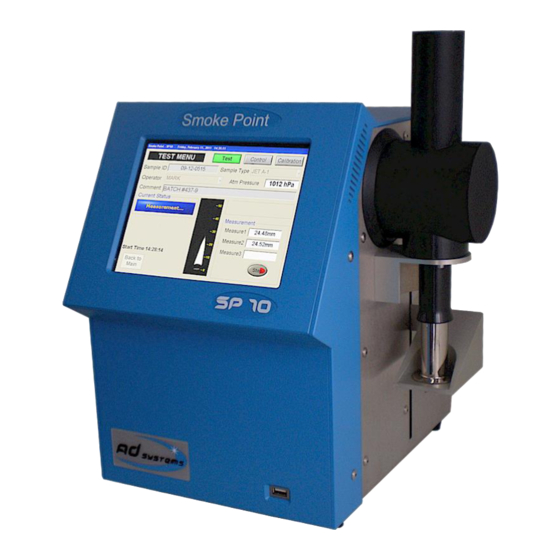
Page 8: Sp 10 Analyzer Description
SP 10 ANALYZER DESCRIPTION SP 10 instrument description: 1 – Full color display with touch screen 2 – Test lamp compartment 3 – Candle 4 – Candle conveyor 5 – USB port on front panel 6 – RJ45 Ethernet socket 7 –... - Page 9 When the flame shape corresponds to the one described in the test method, the SP 10 memorizes the height of the flame. This specific flame is the one with the maximum height without generating smoke. After three consecutive readings, the instrument reports the average value corrected with the lamp factor according to the standard.
-
Page 10: Setup
SETUP Install the SP 10 in an air draft free place on a horizontal flat workbench not subject to vibrations. Provide enough space so that the analyzer can be operated conveniently. Make sure that the cooling fan on rear panel is not obstructed and keep enough space for access to rear connectors. -
Page 11: Switching On
Main Power Connection The SP 10 analyzer operates from 100 to 240 Volts, at 50 or 60 Hz, in accordance with the majority of countries where the analyzer is marketed. ... -
Page 12: Main Menu
Buttons: SMOKE POINT– Press this button to initiate a test operation: Test, Verification or Calibration Refer to section: “SP 10 – Test operation” of the manual for more details. RESULT DATABASE – to access to results archive database Refer to section: “Results database” of the manual for more details. - Page 13 The complete structure of the SP 10 software menus is as follow: The sign means that this menu is protected by a password in order to prevent unauthorized changes of critical instrument settings. Factory set password is 00000 as default.
-
Page 14: Setup Menu
In case of communication with AD Systems technical support department, this information will be requested. How to set Date and Time The “Clock Settings” button allows the setting or adjustment of the date and time. Select the date in the calendar to change the date. -
Page 15: Set Pre-Programmed Lists
In order to memorize the modifications, press Save button prior leaving the menu. Description of Lists: Operators - name of the person performing tests on the SP 10. Maximum 15 characters. Sample Type - identification of fuel type to be tested. Maximum 15 characters. -
Page 16: Set A Password
In order to change the password, go to the menu SETUP/PASSWORD SETTINGS. CAUTION! When you change the password, please, record the new password, it will be not displayed! If you forget your password, please contact AD Systems or its local distributor. Doc : AM220-001E Release: 1.5 updated : October 2014 Page... -
Page 17: Test Procedure - Candle Preparation
The cotton wick structure and textile specification are very well defined in the test method. To obtain right measurements use only wicks conforming to the standard requirements. o AD Systems is the supplier of the wicks conforming to the ASTM D1322 specification. Candle: Soak a piece of extracted and dried wick, not less than 125 mm long, in the sample and place it in the wick tube of the candle. -
Page 18: Use Of Wick Insertion And Trimming Tools
USE OF WICK INSERTION AND TRIMMING TOOLS The “Wick Insertion Tool” (part number: AK220-001) consists of two parts: 1. Wick Insertion Tong (Top) 2. Wick Trim Gauge (Bottom). AK220-001 - SET OF TOOLS FOR WICK INSERTION AND TRIMMING ST220-004 - Tong for wick trimmer Please note that the wick insertion tong is available separately as P/N ST220-004 Instructions: This tool saves a significant amount of time in test preparation, avoids twisting of the wick and fraying of... -
Page 19: Sp 10 - Test Operation
SP 10 – TEST OPERATION Operation principle description The smoke point test with the SP 10 is as simple as is an automated flash point test. Phase 1.The operator prepares the candle according to the test method instructions (see the section “Test procedure –... -
Page 20: Test Modes
At the end of test, the SP 10 instrument calculates the mean value of the three consecutive readings of the smoke point. The result is rounded then corrected with the memorized lamp correction factor. A complete test report is saved in a built‐in data base. It can be printed, transferred on a USB memory stick and/or send to a LIMS when the SP 10 is connected to a LAN. -
Page 21: Perform A Test
Perform a TEST In order to initiate the measurement, the information described here after must be entered. All fields are mandatory with exception of the “Comment” field which is optional. Sample ID - identification of the fuel sample Maximum length for Sample ID field is 15 characters. In order to make an entry, touch the highlighted sensitive area. - Page 22 The barometric pressure value at the test initiation is required in order to find in the SP 10 calibration database the appropriate lamp correction factor corresponding to the barometric pressure at the time of the test.
-
Page 23: Test Interruption
Precautions in use: Use only candles and wick tubes supplied by AD Systems Center the candle on the candle foot print on the conveyor Be sure that candle stands vertically and not inclined. Be sure that wick is straight and not inclined Keep space around the candle conveyor free of any objects, for a free up and down movement. -
Page 24: Test Sequences
0.7 kPa. The SP 10 seeks in the instrument calibration database the reference fuel data corresponding to the above mentioned conditions and calculates the correction factor automatically. If the instrument cannot find reference data exactly matching the conditions, the SP 10 takes the closest available data for the calculation and prompts the operator to perform calibration. -
Page 25: Sp10 - Verification Sample Check
Prepare the candle with the selected verification fuel, place the candle on the conveyor and press START. At the end of the test, the SP 10 reports the measured smoke point and shows the control limits. All verification checks are stored in the result database. Reports can be easily retrieved by the fuel name. -
Page 26: Result Screen
RESULT SCREEN At the end of test, the following test report is displayed: Test details Date: Date of the smoke point measurement test Operator: Name of the operator who performed the test Sample ID: Identification of the jet fuel sample Atm Pressure –... -
Page 27: Control Buttons
To return to the Main Menu or get access to search result database CAUTION! The SP 10 automatically detects the USB drive as soon as it is connected. If the drive capacity is important, its detection could take a few seconds. Consequently it is highly recommended not to connect the USB storage device during test progress. -
Page 28: Calibration
If the instrument cannot find reference data exactly matching the conditions, the SP 10 takes the closest available data for the calculation and prompts the operator to perform calibration. If the SP 10 calibration database is empty, the test is not possible; in that particular case, the calibration should be performed first. - Page 29 Select “CALIBRATION” mode by pressing the corresponding button on the top of the screen Check that the instrument is in “Idle-Ready for test” status In this mode there is no possibility to enter Sample ID. The sample ID field is replaced by the drop-down list of pre-programmed reference fuels and the operator must select the one to be used.
-
Page 30: Calibration History Visualization
Press the “SETUP” button on the Main menu. Select “Calibration List”. Enter the password to see the data. If the SP 10 calibration database is empty, the test is not possible; the calibration should be performed first. Delete the calibration data Normally the calibration database records should not be deleted. -
Page 31: Messages During Operation
The calibration database is empty Other messages In order to assure high quality of the results and safe operation, the SP 10 permanently monitor proper operation of system components. If any malfunction is detected a system message will inform the operator. -
Page 32: Results Database
RESULTS DATABASE The SP 10 built-in result database allows for test data recording, its future retrieval and visualization. Press “Result Database” button on the Main Menu to access the database. A window with the list of the 10 last test reports is opened. The message on the top of the page indicates the total number of results contained in the SP 10 database. -
Page 33: Backup Of Results From The Database
The example on how to find and display a result for a Sample ID “BATCH#422”: Select “Sample ID” as search criterion. Enter Sample ID In the found list, touch the line with result. The test report is displayed. It is possible to print it, save on USB and send to LAN by using control buttons. -
Page 34: Reporting And Storage Options
If the print button is inactive (faded), check if the printer is ON and check the connection cable. Note: It is normal that the SP 10 menu is unavailable for 1 or 2 seconds when the printout starts. Doc : AM220-001E Release: 1.5 updated : October 2014... -
Page 35: Printing Settings
Printing settings The printing modes or formats can be set in the “Storage Settings” menu. Add Calibration Info By checking this box, all calibration details will be printed with the result. This information contains the measured values of the two calibration mixes bracketing the measured result. -
Page 36: Storage Settings
STORAGE SETTINGS SP 10 results can be stored on USB storage device and/or send to Local Area Network (LAN) via Ethernet link. To configure the storage on USB drive and/or Local Area Network (LAN), use the “Storage Settings” button of the “SETUP” menu. - Page 37 “;”. The decimal point is a dot. Depends on the information required, the SP 10 offers two types of report formats. Type 1 Report – contains minimal essential details about test result. The file format is as below:...
-
Page 38: Network Parameters
If it is too long, contact your Network Administrator. When the SP 10 is properly connected to local network, it will be visible by the network server under the name “SP10NUMxxx”; where xxx is serial number of the instrument. The Network Administrator can add SP10NUMxxx user to the network users list, create a shared folder for storage of the SP 10 result files and define the SP10NUMxxx user rights to access to this specified shared folder. - Page 39 Password: PASSword100 If by some reason the default factory settings cannot be used, it is possible to change the username and password of the SP 10 instrument. Use the “Network authentication” button to set the User Name and Password for login into the local network.
-
Page 40: Report Storage On Usb In Ascii Format
Report storage on USB in ASCII format The section “USB Storage Settings” of STORAGE SETTINGS menu contains options to configure the ASCII report storage on the external USB drive. The SP10 has 2 USB ports available: one on the front panel and one on the rear side of analyzer). -
Page 41: Diagnostic
CAUTION! Before leaving the diagnostic menu, the SP 10 checks if all devices are in their original position. If not, the SP 10 puts all devices in its default idle position. This can take a few moments. Doc : AM220-001E Release: 1.5 updated : October 2014... -
Page 42: Firmware Update
CAUTION! Don’t switch off the instrument during the software update procedure! Wait till the instrument automatically restarts. If the SP 10 does not restart, please immediately contact AD Systems Service Department or its local distributor. Doc : AM220-001E Release: 1.5 updated : October 2014... -
Page 43: Maintenance
MAINTENANCE The SP 10 does not require specific maintenance. The digital video camera is installed inside the instrument in a special dust protecting cabinet. The camera is isolated from the lamp by a window made of special optical glass with anti-reflection coating. -
Page 44: Calibration Of Touch Screen Panel
If the optical window surface is contaminated with the soot of combustion, it is possible to clean it. CAUTION! Need to have particular care then cleaning the optical window! Don’t touch the surface with your fingers! Don’t scratch the surface! Air blower may be used to safely remove surface dirt Gently wipe window out using soft non-abrasive Microfiber tissue or Lens Cleaning Cloth saturated with reagent-grade isopropyl alcohol or de-ionized water. - Page 45 In case of instrument failure In case of instrument failure, contact AD Systems local distributor, provide detailed description of the problem in addition with information on the system configuration. The system configuration details are accessible by pressing “SETUP” button of Main Menu.
-
Page 46: Parts And Accessories
PARTS AND ACCESSORIES ACCESSORIES Printer 112mm 230V 50/60Hz AK000-005 Industrial thermal printer. Delivered pre- configured, with cable, adapter and 1 paper roll Printer 112mm 115V 50/60Hz AK000-006 Industrial thermal printer. Delivered pre- configured, with cable, adapter and 1 paper roll AK220-001 - SET OF TOOLS FOR WICK INSERTION AND TRIMMING Set of wick insertion and trimming tools ST220-004 - Tong for wick trimmer... - Page 47 CONSUMABLES AD220-001 Candle AD220-002 Wick tube AC220-001 Wicks for SP 10 Apparatus (pack of 100) Set of 10 printer paper rolls 112mm AC000-001 Doc : AM220-001E Release: 1.5 updated : October 2014 Page...
Need help?
Do you have a question about the SP 10 and is the answer not in the manual?
Questions and answers
Hello Team. We're from the ARAMCO Saudi Arabia. There's a 5 laboratory equipment's Instruments manufacturer with different Model & Serial numbers We need the below following documents: 1. Technical Specification Sheet (Data Sheet) 2. Drawings as per the equipment wise 3. Bill of Material (BOM) as per the equipment wise with Quantity, Ordering Part Number 4. Complete price list for the equipment’s & spare parts list with all replaceable, consumable & wearing spares with ordering part numbers. Attached Saudi Aramco Priced spare parts list format for your perusal. 5. BOM, PSPL-Prices Spare Parts List should be as per the equipment wise with Currency. So that it will be easy for us to map the details to do the catalogue job Kindly send me the reply email to " lakshmi.vadluri@aramco.com " mentioning the sales, services, technical & who is from the local gulf middle east country's supporting on this like supplier, dealer or distributor.