
Related Manuals for AD Systems Deposit Rater DR10

Summary of Contents for AD Systems Deposit Rater DR10
- Page 1 DR10 OPERATION MANUAL Deposit Rater Thermal Oxidation of Aviation Turbine Fuels Measurement of Deposit Tickness On Heater Tubes ASTM D3241 – Annex 2 ITR Doc : AM210-001E Release: 1.4 updated : 2015 Page...
- Page 2 Information in this document is subject to change without notice and does not represent a commitment on the part of AD systems. AD systems provides this document “as is”, without warranty of any kind, either expressed or implied, including, but not limited to, the particular purpose.
- Page 3 The manufacturer accepts no responsibility for any damage or liability arising from the use of analyzers. Use of Non AD systems Products and Accessories: defects or damage that result from the use of Non-AD systems branded or certified Products, Accessories, Software or other peripheral equipment are excluded from warranty.
- Page 4 The above WEEE-symbol is the official marking for equipment under the WEEE-scope. In some EC- Member states "pure B2B equipment" is not necessarily marked with the waste bin symbol. To provide a homogenous EC-wide procedure, AD systems however uses the marking in all EC-Member states. Doc : AM210-001E Release: 1.4 updated : 2015...
-
Page 5: Table Of Contents
CONTENTS CONTENTS ............................... 5 APPLICATION ..............................7 TURBINE FUELS THERMAL OXIDATIONTEST ............Erreur ! Signet non défini. DR10 TECHNICAL DESCRIPTION ........................9 ANALYZER UNPACKING ..........................10 ANALYZER DESCRIPTION ..........................11 SETUP ................................13 SWITCHING ON ............................. 13 SWITCHING OFF ............................13 MAIN MENU .............................. - Page 6 OTHER MESSAGES ............................. 46 FIRMWARE UPDATE ............................47 SERVICE ................................. 48 Revisions ............................... 49 Doc : AM210-001E Release: 1.4 updated : 2015 Page...
-
Page 7: Application
APPLICATION The Jet Fuel Thermal Oxidation Test ASTM D3241 is universally used by the industry to measure high temperature stability of aviation turbine fuels. The ASTM D3241 is required to be run on every batch of Jet Fuel produced according to ASTM D1655 or DEF STAN 91-91 specifications. In this test method the fuel is pumped through heater tube at fixed flow rate and during a specified period of time. -
Page 8: Turbine Fuels Thermal Oxidationtest
TURBINE FUELS THERMAL OXIDATION TEST The ASTM D 3241 is a standard test required to be run on every batch of jet fuel produced according to ASTM D1655 or DEF STAN 91-91 specifications In this test method, the fuel is pumped during a specified period of time at fixed flow rate over an aluminum tube heated at a specified temperature. -
Page 9: Dr10 Technical Description
DR10 TECHNICAL DESCRIPTION The DR 10 uses fiber optic interferometry technique. Broadband wavelength light is emitted on the surface of the heater tube via an optical probe. The reflected light is collected and the interference created by the deposit is processed by the spectrometer. -
Page 10: Analyzer Unpacking
ANALYZER UNPACKING Care in Unpacking After unpacking, verify the unit and its accessories as well as any possible damage sustained in transit, which must immediately brought to the attention of the carrier so that a statement of damage can be made. -
Page 11: Analyzer Description
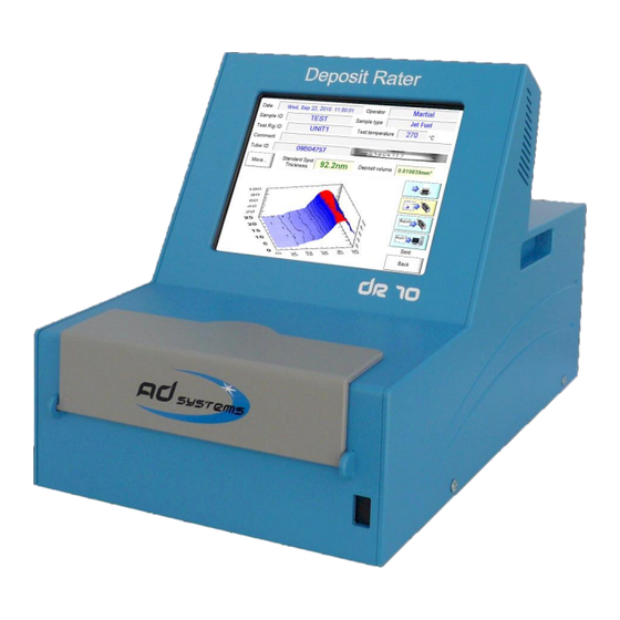
ANALYZER DESCRIPTION The DR 10 instrument presents as follow: 1 – Full color display with touch screen 2 – Test compartment 3 – USB port on front panel 4 – RJ45 Ethernet socket 5 – Cooling fan 6 – Main switch and main power socket 7 –... - Page 12 DR10 test compartment: 9 – Heater tube supports 10 – Optical probe protection cover 11 – Digital camera for tube serial number identification 12 – Door lock switch 13 - Test compartment cover License notice: The DR 10 is using a Windows XPE platform.
-
Page 13: Setup
SETUP Put the DR 10 on a horizontal flat workbench and not subject to vibrations, near electrical sockets. Provide enough space so that the analyzer can be operated conveniently and for access to the rear connectors. Remove the touch screen protection film Note: ... -
Page 14: Main Menu
MAIN MENU Once the DR 10 application is loaded, the instrument is ready for deposit thickness measurement. The Main Menu is as follow: Buttons: TUBE SCAN – Press this button to initiate a deposit rating test Refer to section: “Deposit Rating – Test operation” of the manual for more details. RESULT DATABASE –... - Page 15 The complete structure of the DR10 menus is shown on the following diagram: Sign means that this menu is protected by a password in order to prevent unauthorized changes of critical instrument settings. Factory set password is 00000 as default. This password is active when you receive the instrument.
-
Page 16: Setup Menu
In case of communication with AD Systems technical support department, this information will be requested. How to set Date and Time The “Clock Settings” button allows setting or changing the date and time. Select the date in calendar to change the date. -
Page 17: Set Pre-Programmed Lists
Set pre-programmed lists The “List Settings” button allows entering information which future will be used in drop-down lists. There are five sections in this menu: Operators - identification of the person performing the test. Maximum 15 characters. Sample Type - identification of jet fuel type for reporting. Maximum 15 characters. Temperature - the test temperature (in °C) of jet fuel oxidation in thermal oxidation stability rig during D3421 test. -
Page 18: System Information Ticket
CAUTION! When you change the password, please, record the new password, it will be not displayed! In case if you forget your password, please contact AD systems or its local distributor. System Information Ticket Click on this button to print a ticket with all system’s informations. -
Page 19: Calibration Of Touch Screen Panel
Calibration of touch screen panel In case of repair or replacement of the touch screen, it needs to be calibrated. A special function in the menu SETTINGS facilitates this operation. Press “Touch Screen Calibration” button. If the touch panel is fully misadjusted and it is not possible to use touch screen, connect an USB mouse to the USB port of the instrument and use the mouse to access to the menu. -
Page 20: Deposit Rating - Test Operation
DEPOSIT RATING – TEST OPERATION Note: prior the rating of the heater tube, it is important to make sure that the heater tube has been prepared according to the instructions mentioned in the ASTM D 3241, IP 323 or ISO 6249 test method. Open the door of the DR 10 test compartment Take a heater tube ready to be rated. - Page 21 Sample ID- identification of the jet fuel sample that was used for the oxidation test Maximum length for Sample ID field is 15 characters. In order to make an entry, touch the highlighted sensitive area. The virtual keypad will appear allowing you to type in the required information.
- Page 22 Calibration tube ID – Identification of the tube used for the latest calibration with his brand name and his serial number. Comment – This non mandatory field is used for operator notes or comments; maximum 30 characters. Press “START” button to initiate the measurement. The instrument will load the tube.
- Page 23 Type in the tube serial number corresponding to the number you read. Press ENTER Make sure that the heater tube serial number is right and then press the OK button. A picture of the tube serial number is captured and it will be tagged to the test report for perfect test traceability. During the test initiation, the instrument automatically detects the edge of the tube shoulder and automatically position the optical probe at 5 mm which is the starting point for the...
-
Page 24: Results Reported
RESULTS REPORTED At the end of test, the following test report is displayed: Test results The Standard Spot Thickness is the mean thickness (in nanometers) of the six thickest points in a 2.5 mm area as defined in the ASTM D3241 / IP 323 test method. The area shape of the Standard Spot can be rectangular, square or circular. -
Page 25: Test Information
Test information Date: Date of the deposit measurement test Operator: Name of the operator who performed the test Sample ID: Identification of the jet fuel sample Sample type: Type of jet fuel tested Test Rig ID: identification of the thermal oxidation stability rig used for the oxidation phase Test temperature: Test temperature at which the test sample has been oxidized during the D3421 test TubeID: serial number of the heater tube entered by the operator. -
Page 26: Additional Result Information - Button More
Additional Result information – button MORE Pressing the “MORE” button on the main test result screen gives access to additional test information: Additional test result information: DR10 software version used for the test Scan Matrix is the DR10 scanning matrix used for this measurement. The scanning matrix has a total of 1200 points: ... -
Page 27: Test Report - Particular Case
Average thickness: Average deposit thickness calculated with the 1200 measured points Calibration information: All the details about the DR10 instrument calibration. This information contains the instrument software version at the moment of calibration, date of calibration, the operator name who performed the calibration, the serial number of the heater tube used for the calibration and the serial number of the spectrometer contained in the DR 10 instrument. -
Page 28: Test Operation With User Defined Matrix
TEST OPERATION with User Defined Matrix CAUTION! These specific tests are out of ASTM D3241 test procedure. For specific applications, it’s possible to custom the size of the scan matrix. The different types of spot areas (2.5mm²) are redefined according to the new size of the User Defined Matrix. Set the User Defined Matrix Go to List settings in the Setup Menu. -
Page 29: Start A Test With User Defined Matrix
The Setup of User Defined Matrix is done. In order to memorize the modifications, press SAVE button prior leaving the menu. N.B. With the smallest User Defined Matrix (25x12, 300 pts), the typical time to totally scan a tube is less than 5 minutes. - Page 30 Choose the Standard Matrix the User Defined Matrix (example: 25x12) During the test, this button is displayed but can’t be modified. This button can be removed if User Defined Matrix is reinitialized (X=0, Y=0). Doc : AM210-001E Release: 1.4 updated : 2015 Page...
-
Page 31: Results Database
RESULTS DATABASE The DR 10 result database allows for the recording of the test data and future visualization. Press “Result Database” button on the Main Menu to access the database. A window with the list of the 10 last test reports will be opened. The message on the top of the page indicates the total number of results contained in the DR10 database. - Page 32 The following search criterions are available: Search criterion Available options Description Date Last result Display most recent result in the database Today Display all results of today Last week Display results done in last 7 calendar days Last month Display results done in last 30 calendar days Select a date Display results of specified date (calendar will appear for selection) Select a Period...
-
Page 33: Results Export
RESULTS EXPORT The DR10 offers versatile reporting options. Results can be displayed, printed (with an optional printer), stored on USB storage device and/or send to Local Area Network (LAN) via Ethernet link. To configure the storage on USB drive and/or Local Area Network (LAN), use the “Storage Settings” button of the “SETUP”... -
Page 34: Lan Data Storage
The following options are available: Auto Printing When this box is checked, the result is automatically printed at the end of the test. LAN data storage The section “LAN Storage information” contains options to configure data transmission and storage in Local Area Network (LAN). - Page 35 This error message is displayed if the file with the LAN path is not found by the DR10: Report types Each test report will be transmitted and stored as an individual ASCII file depending on the information required, the DR10 offers three types of ASCII file formats. ASCII files contains multiple lines with a label and data field separated by “;”.
-
Page 36: Network Parameters
Comment Storage tank #29 StdSpot 53.9 Volume 0.012134 #------------------------- StdSpot_idX StdSpot_idY AreaType Average_thickness 24.3 Max_thickness 54.7 MaxThickness_idX MaxThickness_idY ##------------------------ Cal_Date Oct 11,10 17:38 Cal_Software 1.2.2.1 Cal_Operator IGOR Cal_TubeID 10D06121 Cal_SpectroSN 1003194U1 ###----------------------- Type 3Report– contains the same data as Type2 report in addition with the 1200 point thickness deposit values (example of Type3 report is not given in the manual due to its large size). - Page 37 Caution! It takes a few seconds for the system to get an IP address. It is normal that the systems hangs-up for a few seconds after you press the OK button. If it is too long, contact your Network Administrator. When the DR10 is properly connected to local network, it will be visible by the network server under the name “DR10NUMxxx”;...
-
Page 38: Usb Data Storage
The factory set Username is displayed (if no changes had been done yet). The password is not displayed. Enter the default password. Caution! If you are not sure of the password, press CANCEL, contact your Network Administrator. If the username is not modified, the following message is displayed: If you just want to modify the password, press YES Enter the new Password assigned to the analyzer by your Network Administrator. -
Page 39: Report Printout
REPORT PRINTOUT WARNING! Use only a printer supplied or specified by AD systems. The printer is connected to the RS232 port located on the rear of the analyzer. IMPORTANT! The printer MUST be connected to the DR 10 and switched on PRIOR switching on the DR 10 analyzer. -
Page 40: Baseline Calibration
BASELINE CALIBRATION WARNING! The DR 10 instrument is accurately factory calibrated. Don’t recalibrate the unit without necessity. Once the new calibration is performed, there is NO possibility to come back to the original one! Baseline calibration is used to calibrate the spectrometer readout with a brand new (unused) heater tube without deposit. - Page 41 Proceed in the same way as routine thickness measurement: Open the DR10 test compartment cover Identify the location of the tube serial number Carefully place brand new heater tube without deposition the support, the tube serial number must be located on the right. Close the test compartment door and press OK.
-
Page 42: Verification
The absolute measured thickness of this reference thin film and the measurement uncertainty is documented in the certificate, which is delivered with the Thickness Reference Tube. AD systems supplies two reference standards: Part Number : Description AK210-001... - Page 43 If the verification results are out of the acceptance tolerances, perform a DR10 base line calibration as described in the “Baseline Calibration” section and then repeat the verification procedure. If results are still out of acceptance, contact AD Systems service department or its local distributor. Doc : AM210-001E Release: 1.4 updated : 2015...
-
Page 44: Diagnostic
DIAGNOSTIC Use the “Diagnostic” button of the Main Menu to access to instrument diagnostic menus. This dedicated menu allows the checking of all DR10 functions: Camera image used for the reading of heater tube serial number Tube serial number lighting control (LED 1 and LED 2) Operation of the tube loading mechanism o Load and release of the tube Servo-motors operations... -
Page 45: Messages During Test Operation
If the optical systems cannot detect the tube, the following message will be displayed: Check if there is a tube in test compartment If the problem persists, verify that the tube has correct dimensions and if yes, contact AD systems service department. -
Page 46: Other Messages
All messages are self-explaining and provide all necessary instruction to be followed. In case you get such error message not explained in this manual, please contact AD systems service department or its local distributor. Doc : AM210-001E Release: 1.4 updated : 2015... -
Page 47: Firmware Update
Don’t switch off the instrument during the software update procedure! Wait till the instrument automatically restarts. If the DR 10 does not restart, please immediately contact AD systems Service Department or its local distributor. Doc : AM210-001E Release: 1.4 updated : 2015... -
Page 48: Service
SERVICE The DR 10 does not require specific maintenance. In case of instrument failure, contact AD systems local distributor, provide detailed description of the problem in addition with information on the system configuration. The system configuration details are accessible by pressing “SETUP” button of Main Menu. An example is below: Note: Please, do not return the analyzer or any part to the factory without prior factory authorization. -
Page 49: Revisions
Revisions Initial release: 1.0 updated: April 2010 Revision: 1.2 updated: October 2010 Revision: 1.3 updated: January 2011 This manual has been revised to be in phase with the software release version 1.2.3.X of the instrument. This manual contains the following modifications compared to the previous version: Section Modifications CONTENTS...
Need help?
Do you have a question about the Deposit Rater DR10 and is the answer not in the manual?
Questions and answers