Table of Contents
Advertisement
Advertisement
Table of Contents

Related Manuals for Delta Electronics STS30002SR10135

Summary of Contents for Delta Electronics STS30002SR10135
- Page 1 S1- ON NE TW OR K S2- ON RE SE S1- ON NE TW OR K LO CA S2- ON RE SE S1- ON NE TW OR K LO CA S2- ON The power behind competitiveness Delta Infrasuite Power Management Static Transfer Switch User Manual www.deltapowersolutions.com...
- Page 2 Failure to heed these instructions and warnings will void the warranty. Copyright © 2016 by Delta Electronics Inc. All Rights Reserved. All rights of this User Manual (“Manual”), including but not limited to the contents, information, and figures are solely owned and reserved by Delta Electronics Inc.
-
Page 3: Table Of Contents
Features ----------------------------------------------------------- 4 Model Type -------------------------------------------------------- 5 Chapter 3 : Installation ----------------------------------------------------- 7 Installation_Model: STS30002SR00035 ------------------- 7 Installation_Model: STS30002SR10035 ------------------- 8 Installation_Model: STS30002SR10135 ------------------- 9 Chapter 4 : Wiring ----------------------------------------------------------10 Wiring_Model: STS30002SR00035 -----------------------10 Wiring_Model: STS30002SR10035 -----------------------10 Wiring_Model: STS30002SR10135 ----------------------- 11... - Page 4 Top View and Front View of SNMP IPv6 -----------------19 Console Management -----------------------------------------20 Upgrade -----------------------------------------------------------24 STS Command Settings --------------------------------------26 Key Generation for SSH --------------------------------------30 Chapter 8 : Troubleshooting --------------------------------------------32 Appendix 1 : Specifications ---------------------------------------------33 Appendix 2 : Warranty ----------------------------------------------------34 Infrasuite Power Management...
-
Page 5: Chapter 1 : Important Safety Instructions
Upstream circuit breaker must be added for each input. The recommended break- er is D curve 30A for STS30002SR00035 and D curve 32A for STS30002SR10035 and STS30002SR10135. Verify whether the branch circuit breaker or fuse on service feed is correct. -
Page 6: Standard Compliance
1.3 Standard Compliance Safety UL (US) : UL 60950-1 (only for STS30002SR00035) CE (EU) : IEC/EN 60950-1 CISPR 22 Class A and FCC Class A IEC 61000-4-2 IEC 61000-4-6 IEC 61000-4-3 IEC 61000-4-8 IEC 61000-4-4 IEC 61000-4-11 IEC 61000-4-5 IPv6 Certification IPv6 Ready Logo Phase 2 (Core for Host, Logo ID 02-C-000624) 1.4 Storage Please store the STS in its original package and in a dry place. -
Page 7: Chapter 2 : Introduction
2.2 Package List S1- ON S1- ON NE TW OR K NE TW OR K LO CA LO CA S2- ON S2- ON RE SET STS30002SR00035 STS30002SR10035 S1- ON NE TW OR K LO CA S2- ON RE SET STS30002SR10135... -
Page 8: Features
Item Q’ty STS Module 1 PC Bracket Ear 2 PCS Bracket Screw 8 PCS Rack Screw 4 PCS Rack Nut 4 PCS NOTE : 1. If there is any damage or anything missing, please immediately contact the dealer from whom you purchased the unit. 2. -
Page 9: Model Type
Length Type Length 3600mm 450mm STS30002SR00035 L6-30P L6-30R (12 feet) (18 inches) STS30002SR10035 IEC309-32A 4000mm IEC309-32A 1000mm HP-T4049S- HP-T4049S- STS30002SR10135 3P-L2 3P-L2 Model: STS30002SR00035 S1 -O NE TW OR K TE ST LO CA O/ P S2 -O RE SE... - Page 10 Model: STS30002SR10035 S1 -O NE TW OR K TE ST LO CA O/ P S2 -O Model: STS30002SR10135 S1 -O NE TW OR K TE ST LO CA O/ P S2 -O RE SE Infrasuite Power Management...
-
Page 11: Chapter 3 : Installation
Chapter 3 Installation Chapter 3 : Installation 3.1 Installation_Model: STS30002SR00035 Front installation S1-ON NETW ORK LOCA L RESE T TEST S2-ON Rear installation NETW ORK S1-O N LOC AL RES ET TEST S2-O N NOTE : After installation, the surplus four bracket screws, two rack nuts and two rack screws are spare parts. -
Page 12: Installation_Model: Sts30002Sr10035
3.2 Installation_Model: STS30002SR10035 Front installation NETW ORK S1-ON LOCA L RESE T TEST S2-ON Rear installation NETW ORK S1-O N LOC AL TEST RES ET S2-O N NOTE : After installation, the surplus four bracket screws, two rack nuts and two rack screws are spare parts. Infrasuite Power Management... -
Page 13: Installation_Model: Sts30002Sr10135
Chapter 3 Installation 3.3 Installation_Model: STS30002SR10135 Front installation NET WOR S1-O N LOC AL RES ET TES T S2-O N Rear installation NET WOR S1-O N LOC AL TES T RES ET S2-O N NOTE : After installation, the surplus four bracket screws, two rack nuts... -
Page 14: Chapter 4 : Wiring
Chapter 4 : Wiring 4.1 Wiring_Model: STS30002SR00035 Connect the input power cables (provided) to two power sources (source 1 (S1) & source 2 (S2)). Source 1 (S1) is the preferred source. Connect the output power cable (provided) to your load. Connect the Ethernet cable (not provided) to the front panel’s ‘NETWORK’... -
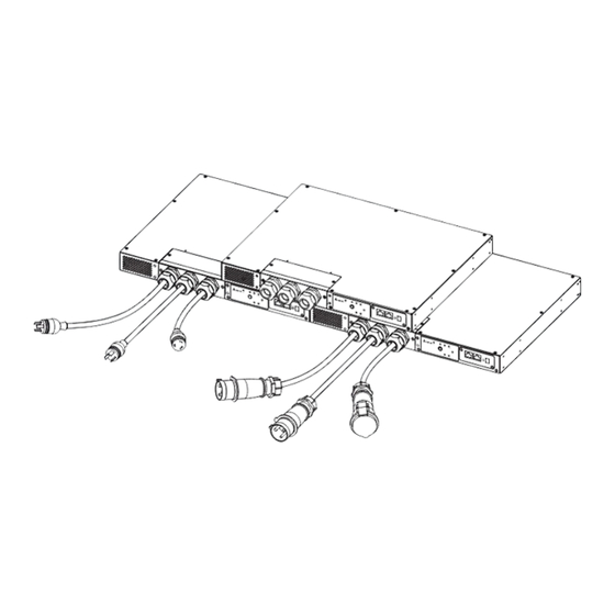
Page 15: Wiring_Model: Sts30002Sr10135
Chapter 4 Wiring S1 -O NE TW OR K TE ST LO CA O/ P S2 -O RE SE 4.3 Wiring_Model: STS30002SR10135 Remove the two screws shown in the figure below. O /P... - Page 16 After removing the two screws, you will see the wiring terminals (L, N, G) as follows. O /P Follow the following table to use the specified wires to connect the wiring terminals and the source 1 (S1), source 2 (S2) and your load. For wiring, please refer the figure below.
-
Page 17: Chapter 5 : Front Panel
Chapter 5 Front Panel Chapter 5 : Front Panel NETWORK LOCAL RESET S1-ON TEST S2-ON Item Description S1 LED Green. The LED indicates the condition of input source 1. If the input source 1 is within the acceptable range, the LED will light up as green. - Page 18 Item Description Test Green. If you press the test button, the STS will be under test and the Test LED will flash (on: 0.5s; off: 0.5s). In normal operation, the LED will be off. Fault Red. If the STS has any internal fault, the LED will light up as red.
- Page 19 Chapter 5 Front Panel Item Description NETWORK Connects to the Ethernet Network. Port LOCAL Connects to a workstation with an RJ45 to DB9 cable to Port configure the system. RESET Resets InsightPower SNMP IPv6 for STS (hereafter referred Button to as SNMP IPv6). This DOES NOT affect the operation of the STS.
- Page 20 Item Description Set up operation mode. Please refer to the following table. Switches DIP Switch 1 DIP Switch 2 Operation Description Switch 1 Switch 2 Mode The built-in SNMP IPv6 provides the STS’s Normal status information and Mode parameters through a network system.
-
Page 21: Chapter 6 : Operation
Chapter 6 Operation Chapter 6 : Operation 2 poles circuit breaker (L1) (N1) (Source 1) To the sensitive equipment 2 poles circuit breaker (L2) (N2) (Source 2) After power connection, the STS will automatically perform power-on self-test. After the test, the STS will start supplying power to its connected equipment. You can also press the Test Button to force the STS to execute self-test. -
Page 22: Chapter 7 : Insightpower Snmp Ipv6 For Sts
Chapter 7 : InsightPower SNMP IPv6 for STS 7.1 Introduction of InsightPower SNMP IPv6 for STS The InsightPower SNMP IPv6 for STS, hereafter referred to as SNMP IPv6, is built in the STS and is a device that provides an interface between the STS and a network. -
Page 23: Top View And Front View Of Snmp Ipv6
Chapter 7 InsightPower SNMP IPv6 for STS - RADIUS (Remote Authentication Dial In User Service) login and local authentication - Remote event log management through syslog - IPv6 Ready Logo certified (ID 02-C-000624) DEFAULT SETTING User Name: admin Password: password DHCP Client: Enable IPv4 Address: 192.168.1.100 7.3 Top View and Front View of SNMP IPv6... -
Page 24: Console Management
7.4 Console Management You can manage the SNMP IPv6 through the LOCAL port. Please use an RJ45 to DB9 cable to connect the SNMP IPv6’s LOCAL port and your workstation’s COM port. Make sure both of the DIP switches are set to the OFF position (normal mode). The baud-rate of the workstation’s COM setting should be 2400 bps. - Page 25 Chapter 7 InsightPower SNMP IPv6 for STS TCP/ IP Setting +========================+ TCP/IP Setting +========================+ [1].IPv4 Address: 192.168.1.100 [2].IPv4 Subnet Mask: 255.255.255.0 [3].IPv4 Gateway IP: 192.168.1.254 [4].IPv4 DNS or WINS IP:192.168.1.254 [5].DHCPv4 Client: Enable [6].IPv6 Address: [7].IPv6 Prefix Length: 0 [8].IPv6 Gateway IP: fe80::226:Sbff:fecc:fdal [9].IPv6 DNS IP: [a].DHCPv6:...
- Page 26 Time Server +========================+ Time Server +========================+ [1].Time Selection: SNTP [2].Time Zone: +0 hr [3].1st Time Server: [4].2nd Time Server: [5].Manual Date: 01/01/2000 (MM/DD/YYYY) [6].Manual Time: 00:00:00 (hh:mm:ss) [0].Back To Previous Menu Please Enter Your Choice => Soft Restart +========================+ Web Card Main Menu +========================+ Web Card Version 01.12.11f MAC Address 00-30-ab-26-b1-b4...
- Page 27 Chapter 7 InsightPower SNMP IPv6 for STS Device Communication You can enter the STS Command Mode below by selecting Device Communi- cation. STS> Vs1 216.8 STS> Vs2 217.9 STS> Iout STS> Vout 217.1 STS> Vbp2s 180.0 STS> Vbs2p 180.0 STS> Tdp2s 12.0 STS>...
-
Page 28: Upgrade
7.5 Upgrade Upgrade via Web You can upgrade the SNMP IPv6’s firmware or the STS’s firmware through the InsightPower SNMP IPv6 for STS Web (please see the following figure). The SNMP IPv6 will restart after finishing self-upgrade. If you upload the STS’s firmware to the Web, you can see the STS’s firmware upgrade progress from the Web. - Page 29 Chapter 7 InsightPower SNMP IPv6 for STS Upgrade via EzSetting You can also upgrade the SNMP IPv6’s firmware or the STS’s firmware by using EzSetting. 1. Click Discover. A list of SNMP devices is shown. Select a device from the Device List, and click Modify.
-
Page 30: Sts Command Settings
3. Click Upgrade. The upgrade dialog box pops up. Click Browse to select a valid firmware binary file. Verify the firmware version shown under File Information, and then click Upgrade Now to continue. 7.6 STS Command Settings Command Description Parameter Response Info Report summary... - Page 31 Chapter 7 InsightPower SNMP IPv6 for STS Command Description Parameter Response DevID Report the unit’s device ID. <Device ID string> Prefer Report the preferred source. S1 or S2 Sens Report the sensitivity. hi or low Mode Report the operation mode. Initialization Diagnosis Safe...
- Page 32 Command Description Parameter Response Tds2p Report the recover time of transfer from secondary to primary. Mvs1 Report the max voltage of comparing cycles for primary AC blackout. Mvs2 Report the max voltage of comparing cycles for secondary AC blackout. Mts1 Report the max time of comparing cycles for primary AC blackout.
- Page 33 Chapter 7 InsightPower SNMP IPv6 for STS Command Description Parameter Response SetDevID Set the unit's device ID. <20 Various kinds characters> alphanumeric only SetVtp2s Set the primary to secondary 165.0 ~ 175.0 Various kinds trip voltage. SetVts2p Set the secondary to primary 165.0 ~ 175.0 Various kinds trip voltage.
-
Page 34: Key Generation For Ssh
Command Description Parameter Response UpPercentage Percentage of upgrade progress. UpResult Result of upgrade progress. OK / No response / File ID fail / Authentication fail / Erase fail / Flash fail / Read fail / Upgrade completion UpDate Report each FW upgrade [Index] [# to hh:mm:ss MM/DD/ time. - Page 35 Chapter 7 InsightPower SNMP IPv6 for STS (3) Select SSH-2 RSA from the Parameters area and click Key→ Generate key pair to generate an RSA key. (4) Select Conversions→ Export OpenSSH Key and assign a file name to the RSA key. Please ignore it when prompted to provide key passphrase. (5) Select SSH-2 DSA from the Parameters area and select Key→...
-
Page 36: Chapter 8 : Troubleshooting
Chapter 8 : Troubleshooting Problem Possible case Solution All LEDs on the The power 1. Check the output (overload/ front panel are off. sources, S1 and short-circuit). S2, are both 2. Check both power sources, S1 absent. and S2. 3. Reset the upstream circuit breakers. -
Page 37: Appendix 1 : Specifications
200/208/220/230/240 Vac Voltage Operating 45Hz to 65HZ Frequency STS30002SR00035 24A for UL/ 25.6A for CE Current Rating STS30002SR10035 30A* STS30002SR10135 30A* STS30002SR00035 43mm x 440mm x 385mm Physical Dimensions STS30002SR10035 43mm x 440mm x 385mm (H x W x D) STS30002SR10135... -
Page 38: Appendix 2 : Warranty
Appendix 2 : Warranty Seller warrants this product, if used in accordance with all applicable instructions, to be free from original defects in material and workmanship within the warranty period. If the product has any failure problem within the warranty period, Seller will repair or replace the product at its sole discretion according to the failure situation. - Page 40 5013212302...
Need help?
Do you have a question about the STS30002SR10135 and is the answer not in the manual?
Questions and answers