
Subscribe to Our Youtube Channel
Related Manuals for Bishamon UNILIFT UNI-20


Summary of Contents for Bishamon UNILIFT UNI-20
- Page 1 UNILIFT P A L L E T T R A N S P O R T E R & P O S I T I O N E R SERVICE SERVICE MANUAL MANUAL MANUAL MANUAL For Serial Numbers 1110803 and Earlier Model UNI-20 Patents Pending...
- Page 2 BISHAMON INDUSTRIES CORPORATION 5651 East Francis Street Ontario, California 91761, USA (909) 390-0055 (800) 231-3187 Date Placed in Service: Serial Number: Dealer:...
-
Page 3: Table Of Contents
Table of Contents Contents Page Getting Started ........................................1 Inspection ..........................................1 Operator Safety ........................................1 Operator Training ......................................1 Safety Defi nitions ......................................1 Dangers, Warning and Cautions ..................................1 Hazard Locations ......................................3 Safety Warning Label Locations ..................................4 Responsibility of Owners/Users .................................. - Page 4 Contents Page Figure 28 - Linkage Lever Arms ..................................16 Figure 29 - Mast Inspection ....................................17 Figure 30 - Brake Lubrication Points ................................. 18 Figure 31 - Outrigger Inspection Points ................................18 Figure 32 - Outrigger Linkage .................................... 19 List of Charts Chart 1 - Daily Inspection Items ..................................
-
Page 5: Getting Started
PLEASE READ THIS MANUAL CAREFULLY BEFORE USING THE UniLift™ Pallet Transporter and Positioner. The safety of all persons installing, using or servicing the UniLift™ is of utmost importance to Bishamon. The UniLift™ is capable of lifting heavy loads and is capable of causing SEVERE PERSONAL INJURY if used improperly or certain safety precautions are not taken. - Page 6 in Figure 1, are created as the forks move up or down. SEVERE PERSONAL INJURY could result. ALWAYS keep hands and fi ngers away the mast and fork carriage. ALWAYS keep feet clear of the rolling wheels and casters. Use care when transporting a palletized load. Improper load handling could cause SEVERE PERSONAL INJURY. PULL or PUSH SLOWLY and avoid sharp turns or rapid maneuvering when handling elevated loads.
-
Page 7: Hazard Locations
CRUSH AND PINCH POINT HAZARDS Figure 1 Hazard Locations... -
Page 8: Safety Warning Label Locations
SAFETY WARNING LABEL LOCATIONS Figure 2 Safety Warning Label Locations... -
Page 9: Responsibility Of Owners/Users
• Ensure any UniLift not in safe operating condition is removed from service and repaired to Bishamon’s standards. Unsafe conditions include, but are not limited to: excessive leakage, missing pins or fasteners, bent or cracked structural members, cut or freyed hydraulic lines and damaged or malfunctioning controls or safety devices. -
Page 10: Functional Description
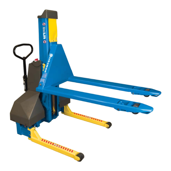
FUNCTIONAL DESCRIPTION The UniLift is a dual purpose pallet positioner and transporter designed to improve palletizing productivity and worker safety. The UniLift allows palletized loads to be transported like a pallet jack then lifted like a stacker. It rolls, steers and maneuvers like a typical pallet jack allowing easy transport and precise positioning. -
Page 11: Preperation For Use
Figure 5 Forklift Lift Points PREPARATION FOR USE Before you begin, locate and identify the components detailed in Figure 6. These components will be referred to throughout the “Installation” and “Operating” procedures. Make sure you understand the function of each component before proceeding. Items Required AC extension cord Figure 6 Installation Components... -
Page 12: Figure 7 Operator Console
Figure 7 Operator Console UP Button – Depress and hold the UP button to run the power unit and raise the forks. From a fully lowered position, the forks will rise to the maximum pallet jack height and stop. To continue, it is required that the UP button be released and then depressed. Their will be a 6 second delay while the outriggers rotate to their extended positions. -
Page 13: Figure 10 Right Outrigger Extended Led Indicators
Right Outrigger Extended – When the right outrigger reaches its fully deployed position, the upper right green LED will illuminate. At this time, the left outrigger is in the fully retracted position, as indicated by the green LED. Figure 10 Right Outrigger Extended LED Indicators Left Outrigger Extending –... -
Page 14: Figure 15 Right Outrigger Stopped Mid-Travel Led Indicators
Right Outrigger Stopped Mid-Travel – If the operator releases the UP or DOWN button with the right outrigger in between it’s fully retracted or fully deployed positions, the right 3 red LEDs will stop scrolling and fl ash. Continue to depress the UP or DOWN button to ensure the right outrigger is either fully retracted or fully extended. -
Page 15: Operating Instructions
OPERATING INSTRUCTIONS General Instructions The UniLift is designed for use with GMA style (48” long x 40” wide) pallets. Dimensions for a standard GMA pallet are identifi ed below in Figure 18. As shown below, the total depth of a GMA pallet is approximately 5 inches (127 mm). For the UniLift to operate properly, the pallet height should not exceed 5 ½... -
Page 16: Pallet Jack Mode Operation
Pallet Jack Mode Operation The UniLift is capable of operating like a pallet jack and will easily transport palletized loads on a smooth level surface. Depress the DOWN button to ensure the forks are fully lowered. Check the position of the brake. If required, rotate the brake pedal to the release position. Insert the forks into a loaded pallet. -
Page 17: Stacker Mode/Positioning A Pallet
If repositioning the pallet height is required, walk to the rear of the unit and turn the ON-OFF switch to ON. Wait 5 seconds, then raise or lower the pallet to the desired height. Turn the ON-OFF switch to OFF, then continue loading or unloading as required. When the loading or unloading process is complete, walk to the rear of the UniLift and turn the ON-OFF switch to ON. -
Page 18: Routine Maintenance
• Structural member securely positioned in the mast Always use extreme care when blocking the unloaded forks in an elevated position. If an acceptable method is not available, Bishamon offers an optional carriage support plate that will secure the elevated fork carriage to the top of the mast. Install the plate as follows: Completely lower the forks and turn the key switch to the OFF position. -
Page 19: Figure 23 Upper Console Cover Removal
Using the Allen wrench, remove the four (4) screws attaching the console plate to the upper console cover. Next, remove the four (4) screws that attach the upper console cover to the lower battery cover. As illustrated in Figure 23, slide the console plate together with the upper console cover top end straight back about one (1) inch and carefully separate the upper console cover from the console plate. -
Page 20: Figure 26 - Mast Cover Clamp
Extreme or unusual operating conditions may require a more extensive inspection and maintenance program. If you have any questions regarding the inspection or maintenance of any UniLift, do not hesitate to contact your local Bishamon dealer or Bishamon Industries Corp. -
Page 21: Chart 1 Daily Inspection Items
Weekly Inspection and Operation Checks Bishamon recommends that several items be inspected on a weekly basis. In addition to the daily inspection, the following items should be inspected every week. If any of the following conditions exist, REMOVE the UniLift from service and contact a qualifi ed service person. -
Page 22: Chart 2 Weekly Inspection Items
Detailed Inspection and Maintenance (After 30 days of use - Every 6 months thereafter) Bishamon recommends that every UniLift be inspected and maintained on a regular basis. Identifi ed below is a suggested detailed inspection and maintenance checklist for normal operating conditions and environments. Extreme or unusual operating conditions may require a more extensive inspection and maintenance program. - Page 23 If spring removal is required, contact your dealer or Bishamon for removal instructions. Bishamon recommends replacing the constant force spring every two (2) years or fi ve thousand (5000) cycles. Lower the forks and turn the key to the OFF position.
-
Page 24: Chart 3 Detailed Inspection And Maintenance
Sling and Constant Force Spring Bishamon recommends replacing the sling and constant force spring every two (2) years or fi ve thousand (5000) cycles. Both require removal of the fork carriage assembly. While not complicated, this should not be attempted without a thorough understanding of the fork carriage removal and installation procedures. -
Page 25: Chart 5 2 Year/5000 Cycle Maintenance Items
In the event the pump or cylinder seals are leaking, detailed instructions and replacement part kits are available. Contact your local dealer or Bishamon Industries Corporation to obtain service kits and instructions for these items. Electrical and Hydraulic Schematic Electrical and hydraulic schematics are available upon request. Contact your local dealer or Bishamon Industries Corporation to obtain the required schematics. -
Page 26: Troubleshooting
Replacement Parts Bishamon has carefully selected the components used in the manufacture of the UniLift. In the event replacement parts are required, ALWAYS use genuine UniLift components provided by Bishamon. These parts can be obtained from your local Bishamon dealer or by contacting Bishamon Industries Corporation For detailed exploded views and parts lists contact your local Bishamon dealer, Bishamon Industries Corporation or visit www.bishamon.com.
Need help?
Do you have a question about the UNILIFT UNI-20 and is the answer not in the manual?
Questions and answers