Table of Contents
Advertisement
Advertisement
Table of Contents

Related Manuals for Homelite HBL26BVB


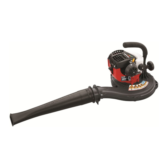
Summary of Contents for Homelite HBL26BVB
- Page 1 HBL26BVB...
- Page 2 Important! It is essential that you read the instructions in this manual before assembling, operating, and maintaining the product. Subject to technical modifications.
-
Page 3: Intended Use
Original instructions | English Safety, performance, and dependability have Never start or run the engine in a closed or ■ been given top priority in the design of your poorly ventilated area; breathing exhaust blower/vacuum. fumes can kill. Clear the work area before each use. ■... - Page 4 Original instructions | English atmosphere. Never use the product with defective ■ guards or shields, or without safety devices Never use the product when you are tired, ■ in place. ill, or under the influence of alcohol, drugs, or medicine. Do not modify the product in any way or ■...
-
Page 5: Blower Safety Warnings
Original instructions | English cap before starting the engine. Never place objects inside the blower ■ tubes. Wipe away any fuel spillage. Move 9 m ■ away from refuelling site before starting Do not place the product on top of or near ■... -
Page 6: Transportation And Storage
Original instructions | English Short term (less than 1 month) severe injury. Stop the engine and ensure that fan blades have stopped rotating Stop the engine and allow the product to ■ before opening the vacuum door, installing cool down before storing or transporting. or changing tubes, or opening or removing Clean all foreign material from the product. -
Page 7: Clearing A Blockage
Original instructions | English authorised service centre. RISK REDUCTION Have the product serviced by an authorised ■ been reported that vibrations service centre to replace damaged or from handheld tools may contribute to a unreadable labels. condition called Raynaud’s Syndrome in certain individuals. - Page 8 Original instructions | English BLOWER TUBE AND NOZZLES VACUUM HANDLE The blower tube can be installed on the blower This feature allows the user to perform without using any tools. vacuuming duties comfortably. POSITIVE SWITCHES VACUUM TUBES The product has positive switches at the The vacuum tubes can be installed on the blowing and vacuuming opening sides.
-
Page 9: Operation
If any parts are damaged or missing, ■ please call your HOMELITE service centre MIXING THE FUEL for assistance. The product is powered by a 2-stroke engine WARNING and requires premixing petrol and 2-stroke oil. -
Page 10: Filling The Tank
Original instructions | English before fuelling. WARNING Mix in small quantities. Do not mix quantities Check for fuel leaks. A leaking fuel cap ■ larger than usable in a 30-day period. A is a fire hazard and must be replaced synthetic 2-stroke lubricant containing a immediately. -
Page 11: Using The Vacuum
Original instructions | English filters. USING THE VACUUM See page 26. Use rakes and brooms to loosen debris ■ before blowing. WARNING dusty conditions, slightly dampen ■ Keep the silencer and all hot surfaces of surfaces when water is available. the blower/ vacuum away from your body. -
Page 12: Cleaning The Exhaust Port, Muf- Fler, And Spark Arrestor
See page 28. and cleaned after 5 hours of operation. Inspect and clean more frequently if used in The engine uses a HOMELITE AC00160, dusty dirty conditions. Champion RCJ-6Y or NGK BPMR7A spark plug with .025 in. electrode gap. Use an exact For best performance, the air filter should be replacement and replace annually. -
Page 13: Symbols In This Manual
Original instructions | English Waste electrical products Beware of thrown or flying should not be disposed of objects. Keep all bystanders, with household waste. Please especially children and pets, recycle where facilities exist. at least 15 m away from the Check with your local authority operating area. -
Page 14: Troubleshooting
Original instructions | English TROUBLESHOOTING Problem Possible causes Solution Engine fails to No fuel in tank. Fill tank. start. Spark plug shorted or Replace spark plug. fouled. Spark plug is broken Replace spark plug. (cracked porcelain or electrodes broken). Ignition lead wire shorted, Contact authorised service centre. - Page 15 Original instructions | English...
- Page 17 1. ON/OFF switch 7. Choke lever 14. Upper vacuum tube for blower mode 8. Primer bulb 15. Blower tube 9. Positive switch at 16. Positive switch at 2. Top handle vacuuming side blowing side 3. ON/OFF switch 10. Vacuum inlet door 17.
- Page 18 (50 : 1) Wear full eye and ear protection, substantial footwear, and Pre-mix 2-stroke engine lubricant and unleaded petrol in a long trousers at all times while operating the product. Do clean container approved for petrol at a 50:1 ratio. not operate the product when barefoot or wearing open sandals.
- Page 19 A. Attach the blower tube. B. Attach the vacuum tubes. 1. Align raised tabs on upper blower tube with the slots on Press slider plate into positive switch’s slot. NOTE: Ensure to attach the blower tube securely to the 1. Align the raised slots on the vacuum bag adaptor with 1.
- Page 21 Cold start engine Warm start engine p.21 p.23 Using the blower Using the vacuum p.25 p.26...
- Page 22 Cleaning the air filter Replacing the spark plug Cleaning the vacuum bag p.28 p.29 p.30 Storing the blower/vacuum Cleaning the blower/vacuum p.31 p.32...
-
Page 23: Starting A Cold Engine
STARTING A COLD ENGINE 1. Loosen the fuel cap slowly by turning it counterclockwise. Remove the fuel cap. Pour the fuel mixture carefully into the tank. Replace and tighten the fuel cap. 2. Set the 2 switches to “I“ (ON) position. 3. - Page 24 5. Set the choke lever to the “HALF“ choke position. 6. Squeeze the throttle trigger. Pull the starter grip until the engine attempts to start. Do not pull the starter grip more than 6 times. 7. When engine starts, wait for 10 seconds. 8.
- Page 25 NOTE: Hold blower as shown, so the air stream can work close to the ground. 9. To stop the engine, toggle either the blower or vacuum switch to the “STOP" position.
-
Page 26: Starting A Warm Engine
STARTING A WARM ENGINE 1. Toggle the 2 switches to the “I“ (ON) position. 2. Press the primer bulb 10 times. Set the choke lever to “RUN“ position. 3. Squeeze the throttle trigger. Pull the starter grip until the engine starts. Do not pull the starter grip more than 6 times. - Page 27 USING THE BLOWER 1. Attach the blower tube to the blower. Refer to the “Getting Started” section for the procedure. 2. Start the blower. Refer to the “Starting a cold engine” or “Starting a warm engine” section for the procedure. 3.
- Page 28 USING THE VACUUM 1. Align the raised slots on the vacuum bag adaptor with the raised locking tabs on the blower housing outlet; push the bag adaptor onto the housing. 2. Twist to lock into place. 3. Press the metal contact into the positive switch slot to make sure the switch is engaged and ready to operate.
- Page 29 5. Open the vacuum inlet door. 6. Align the raised locking tabs with the matching orifice on the upper vacuum tube to secure the upper and lower vacuum tubes together. An audible click can be heard to indicate that the blower tubes are secured.
-
Page 30: Replacing The Spark Plug
REPLACING THE SPARK PLUG 1. To stop the engine, toggle either the blower or vacuum switch to the “STOP” position. 2. Disconnect the lead wire from the spark plug. Using a socket wrench with an extension and spark plug socket, loosen the spark plug by turning it counterclockwise. -
Page 31: Cleaning The Air Filter
CLEANING THE AIR FILTER 1. To stop the engine, toggle either the blower or vacuum switch to the “STOP” position. 2. Press the air filter cover tab to open the air filter cover. Open the air filter cover. 3. Lift the edge of the air filter carefully and peel it out. -
Page 32: Cleaning The Vacuum Bag
CLEANING THE VACUUM BAG 1. To stop the engine, toggle either the blower or vacuum switch to the “STOP” position. 2. To remove the vacuum bag and adaptor, pull off the metal contact, twist the adaptor counterclockwise, and then remove the vacuum bag and adaptor from the blower housing outlet. -
Page 33: Cleaning The Blower/Vac- Uum
CLEANING THE BLOWER/VAC- 1. To stop the engine, toggle either the blower or vacuum switch to the “STOP” position. 2. Clean the blower/vacuum using a brush. WARNING: Avoid using solvents when cleaning plastic parts. Most plastics are susceptible to damage from various types of commercial solvents and may be damaged by their use. -
Page 34: Cleaning The Blower/Vac
CLEANING THE BLOWER/VAC- 1. To stop the engine, toggle either the blower or vacuum switch to the “STOP” position. A1.To remove the blower tube, twist and remove the tube from the blower housing outlet. B1.To remove the vacuum tube assembly, loosen the screws that secure the tube assembly to the inlet cover. - Page 35 B3. Close the vacuum inlet door and secure with the securing screw. B4. To remove the vacuum bag and adaptor, pull off the metal contact, twist the adaptor counterclockwise, and then remove the vacuum bag and adaptor from the blower housing outlet. 2.
-
Page 36: Product Specifications
WARNING PRODUCT SPECIFICATIONS The declared vibration value has been Blower/Vacuum measured with a standard test method Model HBL26BVB and may be used to compare one tool with Rated power 0.65 kW another. Engine displacement 26 cc The declared vibration value may be used in... - Page 40 Imported by: Techtronic Industries Australia Pty. Ltd. 31 Gilby Road, Mount Waverly, VIC 3149, Melbourne, Australia Techtronic Industries NZ Limited 2 Landing Drive, Mangere, Auckland, 2022 , New Zealand 960704016-01...
Need help?
Do you have a question about the HBL26BVB and is the answer not in the manual?
Questions and answers
spark plug gap
The correct spark plug gap for the Homelite HBL26BVB is 0.028–0.031 in. (0.7–0.8 mm).
This answer is automatically generated