Table of Contents
Advertisement
Quick Links
Address: Comprehensive building, Wanyelong science and technology Park, Liyuan
Industrial Zone, Shiyan Street, Bao'an District, Shenzhen City 518108
P.R.CHINA.
Tel:
+86-755-86026600 +86-755- 23230518
Fax:
+86-755-86026300
E-mail: lipei@friendcom.com
Website: http://www.friendcom.cn
SHENZHENG FRIENDCOM TECHNOLOGY DEVELOPMENT CO.,LTD
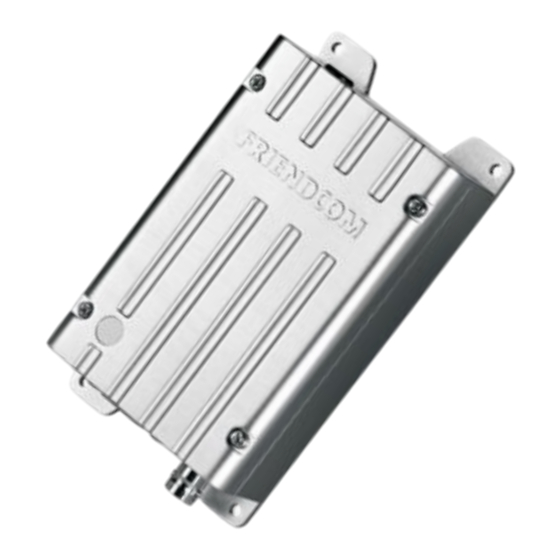
FC-302 Data Radio
User Manual
Advertisement
Table of Contents

Related Manuals for FRIENDCOM FC-302


Summary of Contents for FRIENDCOM FC-302
- Page 1 FC-302 Data Radio User Manual Address: Comprehensive building, Wanyelong science and technology Park, Liyuan Industrial Zone, Shiyan Street, Bao'an District, Shenzhen City 518108 P.R.CHINA. Tel: +86-755-86026600 +86-755- 23230518 Fax: +86-755-86026300 E-mail: lipei@friendcom.com Website: http://www.friendcom.cn SHENZHENG FRIENDCOM TECHNOLOGY DEVELOPMENT CO.,LTD...
-
Page 2: Table Of Contents
FC-302 Data Radio User Manual Content 1 Product Description...............................2 2 Technical Specifications............................3 3.1 Power Supply............................. 5 3.2 RF Channel..............................5 3.3 Data Baseband Circuit..........................6 3.4 Voice Processing Circuit..........................7 3.5 Side Tone Circuit............................7 3.6 CTCSS/DCS...............................8 3.7 Two-Point Balanced Modulation....................... 8 3.8 Channel Selection Circuit.......................... -
Page 3: Product Description
FC-302 Data Radio User Manual 1 Product Description FC-302 is a synthesized 5-watt FM transceiver module, which is designed for data transportation and voice communication. For the voice communication, it can support selected pre-emphasis, squelch and audio amplifier. The radio is PLL(Phase Lock Loop Synthesizer) /microprocessor controlled with optional GMSK, FFSK modem board. -
Page 4: Technical Specifications
FC-302 Data Radio User Manual 2 Technical Specifications General Specification Working Frequency 450MHz~490MHz Channel Spacing 12.5KHz/25KHz Programmable Modulation Type F3D/F3E Number of Channels Nominal Working Voltage 12V DC 9.5 V~16V DC Extreme Working Voltage -40℃~+80℃ Storage Temperature Operating Temperature -30℃~+65℃... - Page 5 FC-302 Data Radio User Manual Receiver Specification <-119dBm Extreme<-115dBm 25KHz Channel Spacing RX Sensitivity (12dB SINAD) <-119dBm Extreme<-115dBm 12.5KHz Channel Spacing 25KHz Channel Spacing >70dB 12.5KHz Channel Spacing >60dB Image Rejection >70dB IF Rejection >70dB Spurious Rejection >70dB Intermodulation Suppression >65dB...
-
Page 6: Power Supply
FC-302 Data Radio User Manual FC-302 is comprised of three PCBs (an Mainboard PCB, a Power board and a Modem PCB). These boards are an 18 pin female and male connector. The digital board is interfaced with external data equipment through the 15 pin d-sub male connector, which controls the radio and data receiving and sending. -
Page 7: Data Baseband Circuit
FC-302 Data Radio User Manual The low-noise band-pass amplifier adopts electric tuning technology,which can automatically adjust the center frequency of band-pass filter based on working frequency, to assure a good selectivity and anti-jamming capability. About the transmission, the frequency synthesizer(PLL) constituted by voltage-controlled oscillator(VCO), phase-locked loop chip and reference frequency source produce a carrier signal,which then is sent to radio... -
Page 8: Voice Processing Circuit
FC-302 Data Radio User Manual 3.4 Voice Processing Circuit Fig.5 Voice Processing Block Diagram When in TX mode, speech signal is transferred from the MIC IN to amplifier with automatic gain control function for amplification , and then is sent to the modulator through the audio frequency pre- emphasis circuit, a limiter circuit and low pass filter. -
Page 9: Ctcss/Dcs
FC-302 Data Radio User Manual transferred to the audio power amplifier to drive trumpet for voice. Then users can hear his own voice when sending the voice. 3.6 CTCSS/DCS Fig.7 CTCSS/DCS Processing Block Diagram CTCSS/DCS encoding and decoding is completed by the MCU. When radio is in TX mode, subaudio sent from the MCU is directly transferred to the carrier modulator-carrier modulation via second-order RC filter. -
Page 10: Interfaces
FC-302 Data Radio User Manual 3.9 Interfaces Mainboard interface: Fig.10 Mainboard Interface Description There are two external interfaces in mainboard. One is J106 and connected to the Power board, transferring available I/O signal to the user through the Power. The other is J100 and connected with modem, customers can develop appropriate modem according to specific requirement. - Page 11 FC-302 Data Radio User Manual Fig.11 Power Board Interface Description Power board J107 is docked with J106, J101 is connected to the external interface (DB9/DB15). Customer can customize and match corresponding interface connector according to the functional requirements. Channel selection switch provides 16 channels for users to choose. The switch encodes the channel number, selected into 4-bit binary code, the binary code plus one equal to the channel number.
- Page 12 FC-302 Data Radio User Manual V23 Modem Interface: Fig.13 V23 Modem Interface Description Modem is designed for data modulation and demodulation. J2 is docked with J100 and CON 1 is connected to Pin 14 in radio external interfaces (DB15). External interfaces:...
- Page 13 FC-302 Data Radio User Manual Fig.14 DB15 FSK1200 (V23) Interface Pin Assignment Fig.15 DB15 Interface Pin Assignment Page 12...
- Page 14 FC-302 Data Radio User Manual Fig.16 DB9 Interface Pin Assignment Mainboard connect to modem(J100---J2) Name Type Description Ground The output signal after the intermediate frequency demodulation in receiver. RFSK 200mVrms,sent to modem Baseband signal input end for the modulation in transmitter, 100mVrms,sent...
- Page 15 FC-302 Data Radio User Manual Mainboard is connected to power board(J106--J107) Name Type Description +12V 12V power supply,used for voltage monitoring BUSY output, dent from mainboard to power board. The default output low BUSY level AUDIO_IN Audio input, Modulation sensitivity is 100mW RX data Microphones signal input from power board to mainboard.
-
Page 16: Features
FC-302 Data Radio User Manual Power board connect to external interface(J101--DB9 or DB15) Name Type Description BUSY detect output, Sent from mainboard to power board. The default output BUSY low level. Also able to work as simulated serial and data transmission port. -
Page 17: Tx Protection
FC-302 Data Radio User Manual transmitter to avoid interference from useless signal. The CTCSS/DCS code can be programmed by PC software. For fast lock time, the CTCSS/DCS is not available for high speed data transmission. 4.3 TX Protection This feature, when enabled, limits the amount of time that the radio can continuously transmit for protecting the radio from block of the channel and damage on radio which is caused by sustained transmission. -
Page 18: Channel Select
FC-302 Data Radio User Manual 3 ---------priority scan, carry with tone 4.11 Channel Select Radio’s 16 channels can be selected by inner dip(4) switch(HW) on power board or serial command inputted from our PC software(SW). Only in SW control mode, channel can be selected by PC software in “Channel”... -
Page 19: Removing & Replacing The Upper Cover
FC-302 Data Radio User Manual 5.2 Removing & Replacing the Upper Cover Removing the Upper Cover 1. Unscrew the four upper cover mounting screws located on the upper cover of radio To replace the Upper Cover 1. Reserve the steps taken to remove the Upper Cover. -
Page 20: Removing & Replacing The Main Board
FC-302 Data Radio User Manual Fig. 21-Shield Plate Assembly Removal 5.4 Removing & Replacing the Main Board 1 Remove the Upper Cover (refer to Removing & Replacing the Upper Cover ) 2 Remove the Power board, Modem Board & Shield Plate (refer to Removing the Power board &... -
Page 21: Repairable/Replaceable Parts List
FC-302 Data Radio User Manual 5.5 Repairable/Replaceable Parts List Fig. 22 Exploded View Page 20... -
Page 22: Accessories Available
FC-302 Data Radio User Manual 6 Accessories Available Please contact the Friendcom sales team for accessory information. sales@friendcom.com Tel: +86 755 23230544 Page 21...
Need help?
Do you have a question about the FC-302 and is the answer not in the manual?
Questions and answers