Table of Contents
Advertisement
Quick Links
Advertisement
Table of Contents

Related Manuals for ProSoft Technology PLX51-DF1-ENI

Summary of Contents for ProSoft Technology PLX51-DF1-ENI
- Page 1 PLX51-DF1-ENI DF1 Router DF1 to EtherNet/IP Router June 27, 2019 USER MANUAL...
- Page 2 Preface Page 2 of 87...
-
Page 3: Table Of Contents
Preface CONTENTS Preface ..........................5 1.1. Introduction to the PLX51-DF1-ENI ................5 1.2. Features ........................6 1.3. Architecture ......................... 7 1.4. Additional Information ....................10 Installation ........................11 2.1. Module Layout ......................11 2.2. Module Mounting ..................... 13 2.3. Power ........................14 2.4. - Page 4 Preface Diagnostics ........................63 5.1. LEDs ........................... 63 5.2. Module Status Monitoring ..................64 5.3. DF1 Packet Capture ....................70 5.4. Module Event Log...................... 73 5.5. Web Server ........................ 74 Technical Specifications ....................75 6.1. Dimensions ........................ 75 6.2. Electrical ........................76 6.3.
-
Page 5: Preface
Preface 1. PREFACE 1.1. INTRODUCTION TO THE PLX51-DF1-ENI This manual describes the installation, operation, and diagnostics of the PLX51-DF1-ENI. The PLX51-DF1-ENI provides intelligent data routing between EtherNet/IP and DF1 which can help simplify the migration from PLC2, PLC3, PLC5, and SLC systems to ControlLogix®... -
Page 6: Features
Preface 1.2. FEATURES The PLX51-DF1-ENI is able to transfer data from a DF1 device to a maximum of eight Logix controllers. The module operates in one of four modes, simplifying the configuration for all applications. Mode Description Message Initiator PLX51-DF1-ENI... -
Page 7: Architecture
When connected to devices that provide more than one DF1 port, it is possible to implement DF1 communication redundancy with the use of two PLX51-DF1-ENI’s. These can be configured in one of two modes, either Simultaneous or Active / Standby. - Page 8 Systems that rely on a central ControlLogix communicating to a number of remote DF1 devices, e.g. MicroLogix and SLC stations, may find the PLX51-DF1-ENI useful when upgrading to newer ControlLogix processors, which no longer have a serial port. These systems can easily be upgraded using the PLX51-DF1-ENI without affecting the existing and often costly wireless infrastructure.
- Page 9 Preface Figure 1.4. – Remote MicroLogix System Figure 1.5. – Remote Programming (Half-duplex) Page 9 of 87...
-
Page 10: Additional Information
1.4. ADDITIONAL INFORMATION The following documents contain additional information that can assist you with the module installation and operation. Resource Link PLX50 Configuration Utility Software www.prosoft-technology.com PLX51-DF1-ENI User Manual PLX51-DF1-ENI Datasheet www.prosoft-technology.com Example Code & UDTs www.cisco.com/c/en/us/td/docs/video/cds/cde/cde205_220_420/i Ethernet wiring standard nstallation/guide/cde205_220_420_hig/Connectors.html... -
Page 11: Installation
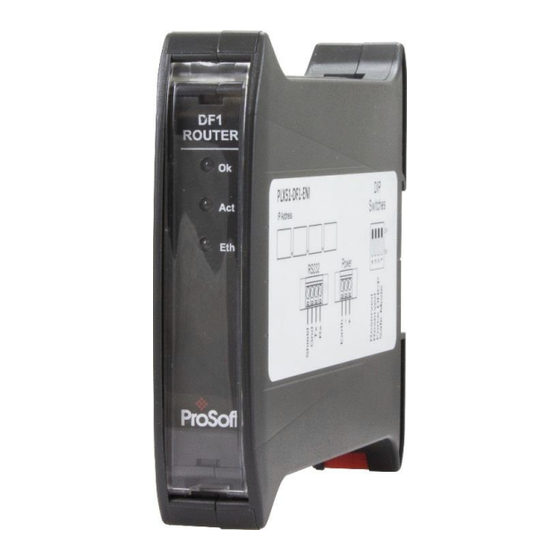
The Ethernet cable must be wired according to industry standards, which can be found in the additional information section of this document. Figure 2.1. - PLX51-DF1-ENI side and bottom view Page 11 of 87... - Page 12 Ethernet interface, and the auxiliary communication interface (RS232). Figure 2.2. – PLX51-DF1-ENI front and top view The module provides four DIP switches at the top of the enclosure as shown in the top view figure above.
-
Page 13: Module Mounting
Installation 2.2. MODULE MOUNTING The module provides a DIN rail clip to mount onto a 35mm DIN rail. Figure 2.3 - DIN rail specification The DIN rail clip is mounted on the bottom of the module, toward the back. Use a flat screw driver to pull the clip downward. -
Page 14: Power
NOTE: When using a shielded cable, it is important that only one end of the shield is connected to earth to avoid current loops. It is recommended to connect the shield to the PLX51-DF1-ENI module, and not to the other DF1 device. -
Page 15: Setup
Setup 3. SETUP 3.1. INSTALL CONFIGURATION SOFTWARE The network setup and configuration of the PLX51-DF1-ENI is done in the ProSoft PLX50 Configuration Utility. This software can be downloaded from www.prosoft-technology.com. Figure 3.1. - ProSoft PLX50 Configuration Utility Environment Page 15 of 87... -
Page 16: Network Parameters
Setup 3.2. NETWORK PARAMETERS The module has DHCP (Dynamic Host Configuration Protocol) enabled as factory default. Thus, a DHCP server must be used to provide the module with the required network parameters (IP address, subnet mask, etc.). There are a number of DHCP utilities available, however it is recommended that the DHCP server in the PLX50 Configuration Utility be used. - Page 17 Setup To assign an IP address, click on the corresponding “Assign” button. The IP Address Assignment window opens. Figure 3.4. - Assigning IP Address The required IP address can then be either entered, or a recently used IP address can be selected by clicking on an item in the Recent List.
- Page 18 Setup NOTE: It is important to return DIP switch 2 back to the Off position, to avoid the module returning to a DHCP mode after the power is cycled again. In addition to the setting the IP address, a number of other network parameters can be set during the DHCP process.
- Page 19 Setup Right-clicking on a device, reveals the context menu, including the Port Configuration option. Figure 3.8. - Selecting Port Configuration The Ethernet port configuration parameters can be modified using the Port Configuration window. Figure 3.9. - Port Configuration Alternatively, these parameters can be modified using RSLinx. Page 19 of 87...
-
Page 20: Creating A New Project
Setup 3.3. CREATING A NEW PROJECT Before you configure the module, a new PLX50 Configuration Utility project must be created. Under the File menu, select New. Figure 3.10. - Creating a new project A PLX50 Configuration Utility project will be created, showing the Project Explorer tree view. To save the project use the Save option under the File menu. - Page 21 Setup In the Add New Device window, select the PLX51-DF1-ENI, and click the Ok button. Figure 3.12 – Selecting a new PLX51-DF1-ENI The device appears in the Project Explorer tree as shown below, and its configuration window opened. The device configuration window can be reopened by either double clicking the module in the Project Explorer tree or right-clicking the module and selecting Configuration.
-
Page 22: Df1 Parameters
In DF1 Slave mode, the module automatically routes the DF1 message and function to the correct Logix tag. In this mode, the PLX51-DF1-ENI maps the DF1 request to the preconfigured tag. Communication in this mode is initiated by the remote DF1 device. - Page 23 Setup The DF1 General configuration window is opened by either double clicking on the module in the tree or right-clicking the module and selecting Configuration. Figure 3.14. - General Configuration Page 23 of 87...
- Page 24 Setup The Serial - DF1 configuration tab is shown in the figure below. The DF1 Serial configuration window is opened by either double clicking on the module in the tree or right-clicking the module and selecting Configuration. Figure 3.15 - Serial DF1 configuration The Serial –...
- Page 25 This configures the module to check for duplicate packets and flagging them Duplicate Detection when they occur. Enable Store and Forward When using the Radio Modem protocol, the PLX51-DF1-ENI can be used to repeat messages from other nodes on the radio network (only relevant for DF1 Radio Modem protocol). Repeat Delay...
-
Page 26: Message Routing
Setup 3.5. MESSAGE ROUTING The module can be configured to route DF1 data in one of four modes: Bridge mode DF1 Slave mode Schedule Tag mode Unscheduled mode 3.5.1. B RIDGE The Bridge Mode can be used for redirecting messages between the DF1 and Ethernet port. This mode allows for various remote programming options and well as mapping DF1 (PCCC) messages to a Logix controller when using the Logix PLC mapping feature. - Page 27 Setup The module can emulate more than one destination DF1 Node Address, and thus route multiple messages to different Ethernet devices. For this reason it is important to enter the correct associate DF1 Node address in each mapping record. When using PCCC data messaging the connection class can be configured by selecting either Class 3 or Unconnected (UCMM) messaging.
- Page 28 Description DF1 Node Address This parameter is one of the destination addresses that the PLX51-DF1-ENI will accept. When the DF1 message initiator sends a message to a specific DF1 node address that has been configured in the module, it will be accepted and routed to the paired Controller Path.
- Page 29 Setup 3.5.1.1. BRIDGE MODE - REMOTE PROGRAMMING The following example makes use of the PLX51-DF1-ENI to program multiple SLC / MicroLogix stations connected on Ethernet, across a serial DF1 radio network. Figure 3.19. – Remote Programming Example 1 The PLX51-DF1-ENI is configured in a Half-Duplex mode, to allow multiple EtherNet/IP devices.
- Page 30 Setup The configured nodes (1 & 2) must also be added to the Polling list definition. Figure 3.21. – Remote Programming Example 1 – RSLinx Configuration Once configured the two remote stations will appear in the RSLinx RSWho browser and can be accessed by RSLogix 500.
- Page 31 After adding the EtherNet/IP driver in RSLinx, the PLX51-DF1-ENI will automatically appear. For the routing to work, the EDS file must be installed, which can be uploaded from the device. The remote serial device will appear under the PLX51-DF1-ENI’s DF1 Port in the RSLinx RSWho browser.
- Page 32 3.5.1.2. BRIDGE MODE – DATA MAPPING In Bridge mode the PLX51-DF1-ENI will redirect a DF1 PCCC message to a Logix controller at a preconfigured path. Therefore, in this mode, the module will rely on the Logix controller to map the DF1 request to the preconfigured Logix tag.
- Page 33 Setup Figure 3.26 – Example 2 – Bridge routing map – node 7 The second part of the Bridge routing map setup is to map the DF1 request received by the Logix controller to a Logix tag. This must be done in Rockwell Automation’s RSLogix 5000. Refer to the additional information section in this document for further information regarding mapping of PLC/SLC messages in the Logix controller.
-
Page 34: Df1 Slave Mode
Thus, the routing of the Node address to Logix controller as well as DF1 File Number to a Logix tag is managed by the PLX51-DF1-ENI where in Bridge mode, the DF1 File Number was routed to a tag by the Logix controller. In the DF1 Slave mode, the PLX51-DF1-ENI can operate completely independently from the Logix controller by directly reading and writing to Logix tags. - Page 35 Setup If the EtherNet/IP module is a bridge module, it can be expanded by right-clicking on the module and selecting the Scan option. Figure 3.29. - Scanning node in the Target Browser Figure 3.30. - Target Browser selection The required Logix controller can then be chosen by selecting it and clicking the Ok button, or by double-clicking on the controller module.
- Page 36 Setup The second part of the DF1 Slave mode is to configure the link between a DF1 node and File Number combination to a Logix tag. This will allow the DF1 message initiator to effectively write to, or read from, a Logix tag using traditional File Numbers (e.g. N7, F8, etc.). Figure 3.31.
- Page 37 Setup Figure 3.32 – DF1 Slave Mapping (PLC2 Messages) NOTE: When using Unprotected Bit Write PLC-2 messages only one byte worth of bits can be written at a time. The module can emulate more than one destination DF1 Node Address, and thus route multiple messages to different Logix controllers.
- Page 38 Setup NOTE: When mapping PLC5 Boolean files (e.g. B3), it is recommended that the destination Logix tag be a SINT array, rather than a Boolean array. Using the latter may result in unexpected results due to the packing format of Logix Boolean arrays.
- Page 39 Setup Figure 3.34 - DF1 Slave mode configuration in the PLX50 Configuration Utility When receiving PLC2 messages, the Data File entered into the PLX50 Configuration Utility will be “PLC2” because there are no Data Files in PLC2 message structures. Thus, the DF1 Node address will be used to route the messages as shown below: NOTE: It is your responsibility to ensure that the Logix tag array datatype and size matches that of the PLC2 DF1 request.
-
Page 40: Scheduled Tag Mode
Unlike the Bridge and DF1 Slave mode, the PLX51-DF1-ENI when in the Scheduled Tag mode initiates the messaging. In this mode, the PLX51-DF1-ENI transfers data between a Logix controller and a DF1 device without any configuration or programming required in either the DF1 device or the Logix controller. - Page 41 Setup If the EtherNet/IP module is a bridge module, it can be expanded by right-clicking on the module and selecting the Scan option. Figure 3.37 - Scanning node in the Target Browser` Figure 3.38 - Target Browser selection The required Logix controller can then be chosen by selecting it and clicking the Ok button, or by double-clicking on the controller module.
- Page 42 Setup The third step is to configure the link between a DF1 node and File Number combination to a Logix tag, and the associated action and scan required. Figure 3.39 - Scheduled Tag Mapping The Logix Function field specifies whether the transaction will result in a read or write from the Logix controller’s perspective.
-
Page 43: Unscheduled Mode
Setup One of the Target Names configured in the first step can be selected by means of the target Name combo box. The Target Tag can be either entered manually or selected using the Tag Browser in the PLX50 Configuration Utility. The Tag Browser requires the controller to be available on the network. To browse to the tag, click on the Browse button. -
Page 44: Module Download
IP address of the module, as set in the module configuration. It can be modified if the PLX51-DF1-ENI is not on a local network. The Connection path can be set by right-clicking on the module and selecting the Connection Path option. - Page 45 Setup To initiate the download, right-click on the module and select the Download option. Figure 3.43 - Selecting Download Once complete, you will be notified that the download was successful. Figure 3.44 - Successful download During the download process, the module’s time will be compared to that of the PC’s time. Should the difference be greater than 30 seconds, you will be prompted to set the module time to that of the PC time.
- Page 46 Setup The module time is used only for the event log. Within the PLX50 Configuration Utility environment, the module will be in the Online state, indicated by the green circle around the module. The module is now configured and will start operating immediately. Figure 3.46 - Module online Page 46 of 87...
-
Page 47: Rslogix 5000 Configuration
Setup 3.7. RSLOGIX 5000 CONFIGURATION The PLX51-DF1-ENI modules can be easily integrated with Allen-Bradley Logix family of controllers. For Logix versions 20 and beyond, the modules can be added using the EDS Add-On-Profile (AOP), which is described in section 3.7.1. - Page 48 Figure 3.48 – Adding a module The module selection dialog opens. To quickly find the module, use the Vendor filter to select the ProSoft Technology modules as shown in the figure below. Figure 3.49 – Selecting the module Page 48 of 87...
- Page 49 Setup Locate and select the PLX51-DF1-ENI module, and select the Create option. The module configuration dialog opens, where you must specify the Name and IP address as a minimum to complete the instantiation. Figure 3.50 – Module instantiation Once the instantiation is complete, the module appears in the Logix IO tree.
- Page 50 Setup The Module Defined Data Types are automatically created during the instantiation process. These data types provide meaningful structures to the module data. An excerpt of the Input Image is shown in the following figure. Figure 3.52 – Module Defined Data Type Page 50 of 87...
-
Page 51: Rslogix 5000 Configuration (Pre-Version 20)
The module can operate in both a Logix “owned” and standalone mode. When the module operates in “owned” mode, the PLX51-DF1-ENI needs to be added to the RSLogix 5000 IO tree as a generic Ethernet module. This is done by right clicking on the Ethernet Bridge in the RSLogix 5000 and selecting New Module. - Page 52 1 (32-bit) Configuration 0 (8-bit) Table 3.4 - RSLogix class 1 connection parameters for the PLX51-DF1-ENI Figure 3.54 - RSLogix General module properties in RSLogix 5000 NOTE: You will need to enter the exact connection parameters before the module will establish a class 1 connection with the Logix controller.
- Page 53 Setup Figure 3.55 - Connection module properties in RSLogix 5000 Once the module has been added to the RSLogix 5000 IO tree, assign the User Defined Types (UDTs) to the input and output assemblies. You can import the required UDTs by right-clicking on User-Defined sub-folder in the Data Types folder of the IO tree, and selecting Import Data Type.
- Page 54 An example Unscheduled Message instruction with the associated Tags To change the routine to map to the correct PLX51-DF1-ENI module instance name, make sure that the mapping routine is called by the Program’s Main Routine. Figure 3.59 - Imported RSLogix 5000 objects Refer to the additional information section of this document for an example RSLogix 5000 project, as well as the required UDTs.
-
Page 55: Operation
4. OPERATION 4.1. MESSAGE ROUTING When the PLX51-DF1-ENI has been set up, the DF1 message initiator sends a read/write to a DF1 address, then routed to a Logix tag. There are various indicators to determine if the mapping has routed the DF1 messages correctly. Refer to the diagnostics section for a more detailed explanation. -
Page 56: Input Assembly
Operation 4.2.1. I NPUT SSEMBLY The following parameters are used in the input assembly of the module. Parameter Datatype Description Instance STRING The instance name of the module that was configured under the general DF1 configuration in the PLX50 Configuration Utility. Status.BridgeMode BOOL Set if the module is operating in Bridge mode. -
Page 57: Output Assembly
Table 4.2 - RSLogix 5000 output assembly parameters 4.3. UNSCHEDULED MESSAGING When the PLX51-DF1-ENI is configured in Unscheduled Mode, it processes DF1 message requests sent from Logix via a message instruction. To simplify the configuration of the required message, a number of UDTs have been preconfigured. - Page 58 Operation Figure 4.3. - Message Configuration Parameter Description Message Type CIP Generic Service Type Custom Service Code 6A (Hex) - Unscheduled DF1 Pass-through Class 408 (Hex) Instance Attribute Source Element The request tag instance. It must follow the structure of the ProSoftDF1RMsgRequest UDT.
- Page 59 Operation Figure 4.4. - Messsage Configuration - Communication The Path must be configured to that of the PLX51-DF1-ENI. If the PLX51-DF1-ENI has been added in the I/O tree, the Browse option can be used to select the path. Alternatively, enter the CIP path in the format :...
- Page 60 Operation The request tag (e.g. DF1RMsgrequest) should be configured as: Figure 4.5. - Unscheduled Message Request Tag Parameter Description Destination Node The DF1 node address of the destination device. Data File Address A string representing the Data File Address of the destination DF1 device.
- Page 61 Operation Parameter Description Status The status returned by the destination DF1 device. A value of zero indicates success. Response Length The number of bytes returned by the destination DF1 device. Response Data The data response from the destination DF1 device expressed as an INT array.
- Page 62 Operation Page 62 of 87...
-
Page 63: Diagnostics
Diagnostics 5. DIAGNOSTICS 5.1. LEDS The PLX51-DF1-ENI provides three LEDs for diagnostic purposes as shown below. Figure 5.1 - PLX51-DF1-ENI front view Description Module The Module LED provides information regarding the system-level operation of the module. If the LED is red, the module is not operating correctly. For example, if the module application firmware has been corrupted or there is a hardware fault the module will have a red Module LED. -
Page 64: Module Status Monitoring
Diagnostics 5.2. MODULE STATUS MONITORING The PLX51-DF1-ENI provides a range of statistics that can assist with module operation, maintenance, and diagnostics. The statistics can be accessed in full by the PLX50 Configuration Utility or using the web server in the module. - Page 65 Diagnostics The Status monitoring window can be opened by either double-clicking on the Status item in the Project Explorer tree, or by right-clicking on the module and selecting Status. The status window contains multiple tabs to display the current status of the module. Figure 5.4.
- Page 66 Diagnostics The General tab displays the following general parameters. It can also be used to set the module time to the PC time: Parameter Description Mode Indicates the current operating mode: Bridge, DF1 Slave, Scheduled Tag, or Unscheduled. Owned Indicates whether or not the module is currently owned (Class 1) by a Logix controller.
- Page 67 Diagnostics Figure 5.5. - Status monitoring - Transactions The Transactions tab displays the statistics associated with the following: DF1 messages PCCC messages (Bridge and Scheduled Tag Mode) Logix Tag Mapping (DF1 Slave and Scheduled Tag Mode) Statistic Description Tx Packet Count The number of DF1 packets sent by the module.
- Page 68 This may be caused by the External Access property of the Logix tag being set to either None or Read Only. Tag Reads The number of tag read transactions executed by the PLX51-DF1-ENI module. Tag Writes The number of tag write transactions executed by the PLX51-DF1-ENI module.
- Page 69 Diagnostics Figure 5.6. - Map Item status Page 69 of 87...
-
Page 70: Df1 Packet Capture
Diagnostics 5.3. DF1 PACKET CAPTURE The module provides the capability to capture the DF1 traffic for analysis. To invoke the capture of the module, double-click on the DF1 Packet Capture item in the Project Explorer tree. Figure 5.7. - Selecting DF1 Packet Capture The DF1 Packet Capture window opens and automatically starts capturing all DF1 packets. - Page 71 Diagnostics To display the captured DF1 packets, the capture process must first be stopped by pressing the Stop button. Figure 5.9. - DF1 Packet Capture complete The captured DF1 packets are tabulated as follows: Statistic Description Index The packet index, incremented for each packet sent or received. Time The elapsed time since the module powered up.
- Page 72 Diagnostics The packet capture can be saved to a file for further analysis by selecting the Save button on the toolbar. Previously saved DF1 Packet Capture files can be viewed by selecting the DF1 Packet Capture Viewer option in the tools menu. Figure 5.10.
-
Page 73: Module Event Log
Diagnostics 5.4. MODULE EVENT LOG The PLX51-DF1-ENI module logs various diagnostic records to an internal event log. These logs are stored in non-volatile memory and can be displayed using the PLX50 Configuration Utility or via the web interface. To view them in the PLX50 Configuration Utility, select the Event Viewer option in the Project Explorer tree. -
Page 74: Web Server
Diagnostics 5.5. WEB SERVER The PLX51-DF1-ENI provides a web server allowing a user without the PLX50 Configuration Utility or RSLogix 5000 to view various diagnostics of the module. This includes Ethernet parameters, system event log, advanced diagnostics, and application diagnostics (DF1 diagnostics). -
Page 75: Technical Specifications
Technical Specifications 6. TECHNICAL SPECIFICATIONS 6.1. DIMENSIONS Below are the enclosure dimensions as well as the required DIN rail dimensions. All dimensions are in millimetres. Figure 6.1 - PLX51-DF1-ENI enclosure dimensions Figure 6.2 - Required DIN dimensions Page 75 of 87... -
Page 76: Electrical
Technical Specifications 6.2. ELECTRICAL Specification Rating Power requirements Input: 10 to 28V DC, (70 mA @ 24 VDC / 130 mA @ 10 VDC) Power consumption 1.7 W Connector 3-way terminal Conductors 24 to 18 AWG Enclosure rating IP20, NEMA/UL Open Type Temperature -20°C to 70°C Earth connection... -
Page 77: Df1
6.4. DF1 Specification Rating Connector 4-way terminal Conductor 24 to 18 AWG Isolation voltage 2.5 kV Protocol DF1 Full Duplex, DF1 Half Duplex, DF1 Radio Modem BAUD 1200, 2400, 4800, 9600, 19200, 38400, 57600, 115200 Parity None, Even, Odd Data bits Stop bits Error detection CRC, BCC... - Page 78 Page 78 of 87...
-
Page 79: Appendix
7.1. EXAMPLE - LOGIX CPU TO DF1 BRIDGE MODE This example demonstrates how to issue a message instruction from an EtherNet/IP–based ControlLogix or CompactLogix CPU, to a DF1 device. 1 Set the PLX51-DF1-ENI to operate in Bridge mode. Page 79 of 87... - Page 80 Appendix 2 In the Serial - DF1 tab, ensure the settings match that of your DF1 device (this example is using a MicroLogix 1100). Also, uncheck the E box. Do this NABLE UPLICATE ETECTION in your DF1 device, as well. 3 You will not need to edit the default settings in the Bridge tab.
- Page 81 5 In the Logix MSG instruction Communication tab, specify the following Path: 2, <IP>, 3, <DF1nodeID> Where: EtherNet/IP 192.168.22.207 PLX51-DF1-ENI IP address PLX51-DF1-ENI DF1 port DF1 Node ID of MicroLogix 1100 6 In this example, the MicroLogix 1100 DF1 Ch0 port configuration is shown below: Page 81 of 87...
- Page 82 Appendix 7 Here are example values after a successful MSG. In the MicroLogix 1100: In the L36ERM: Page 82 of 87...
-
Page 83: Support, Service & Warranty
Support, Service & Warranty 8. SUPPORT, SERVICE & WARRANTY 8.1. CONTACTING TECHNICAL SUPPORT ProSoft Technology, Inc. is committed to providing the most efficient and effective support possible. Before calling, please gather the following information to assist in expediting this process: Product Version Number... - Page 84 Support, Service & Warranty Europe / Middle East / Africa Asia Pacific Regional Office Regional Office Phone: +33.(0)5.34.36.87.20 Phone: +60.3.2247.1898 europe@prosoft-technology.com asiapc@prosoft-technology.com Languages spoken: French, English Languages spoken: Bahasa, Chinese, English, Japanese, REGIONAL TECH SUPPORT Korean support.emea@prosoft-technology.com REGIONAL TECH SUPPORT support.ap@prosoft-technology.com Middle East &...
-
Page 85: Warranty Information
8.2. WARRANTY INFORMATION For complete details regarding ProSoft Technology’s TERMS & CONDITIONS OF SALE, WARRANTY, SUPPORT, SERVICE AND RETURN MATERIAL AUTHORIZATION INSTRUCTIONS, please see the documents at: www.prosoft-technology.com/legal Documentation is subject to change without notice. Page 85 of 87... - Page 86 Page 86 of 87...
-
Page 87: Index
Index 9. INDEX assembly instance, 52 LED, 63 Logix tag, 22, 32, 33, 34, 36, 38, 39, 40, 42, 43, 56, 58 Logix Tag Map, 34, 38 checksum, 24, 63 CompactLogix, 10 ControlLogix, 7 output assembly, 56, 57, 66 DC power, 11 PLC5, 5 DF1 general configuration, 23 PLX50 Configuration Utility, 21, 22, 37, 38, 43, 56...
Need help?
Do you have a question about the PLX51-DF1-ENI and is the answer not in the manual?
Questions and answers