
Related Manuals for Daikin VKM50GAV1

Summary of Contents for Daikin VKM50GAV1
- Page 1 Si71 - 812 Heat Reclaim Ventilation - with DX coil - [Applied Models] 50GAV1 80GAV1 VKM 100GAV1 VKM 50GAMV1 VKM 80GAMV1 VKM 100GAMV1...
-
Page 2: Table Of Contents
Si71-812 Heat Reclaim Ventilation - with DX coil - 50GAV1 80GAV1 VKM 100GAV1 VKM 50GAMV1 VKM 80GAMV1 VKM100GAMV1 1. Introduction .................... iv 1.1 Safety Cautions ..................iv Part 1 General Constructions ............1 1. General Information ................2 1.1 Features ....................2 Part 2 Product Specification ............ - Page 3 Si71-812 Part 5 Control Functions............. 45 1. Control Functions ..................46 1.1 Explanation of individual Functions ............46 1.2 Layout of Switches on Printed Circuit Board ..........52 Part 6 Troubleshooting ............... 53 1. Troubleshooting by Remote Controller ..........54 1.1 The INSPECTION / TEST Button............54 1.2 Self-diagnosis by Wired Remote Controller ...........55 2.
- Page 4 Si71-812 Part 8 Appendix................89 1. Appendix ....................90 1.1 Wiring Diagram..................90 1.2 List of Electrical and Functional Parts ............92 2. Piping Diagram..................93 Index ..................... i Drawings & Flow Charts ............... iii Table of Contents...
-
Page 5: Introduction
Introduction Si71-812 1. Introduction Safety Cautions Cautions and Be sure to read the following safety cautions before conducting repair work. The caution items are classified into “ Warning” and “ Caution”. The “ Warning” Warnings items are especially important since they can lead to death or serious injury if they are not followed closely. - Page 6 Si71-812 Introduction Caution Do not repair the electrical components with wet hands. Working on the equipment with wet hands can cause an electrical shock. Do not clean the air conditioner by splashing water. Washing the unit with water can cause an electrical shock. Be sure to provide the grounding when repairing the equipment in a humid or wet place, to avoid electrical shocks.
- Page 7 Introduction Si71-812 Warning Be sure to use the specified cable to connect between the indoor and outdoor units. Make the connections securely and route the cable properly so that there is no force pulling the cable at the connection terminals. Improper connections can cause excessive heat generation or fire.
- Page 8 Si71-812 Introduction Caution Check to see if the parts and wires are mounted and connected properly, and if the connections at the soldered or crimped terminals are secure. Improper installation and connections can cause excessive heat generation, fire or an electrical shock. If the installation platform or frame has corroded, replace it.
- Page 9 Introduction Si71-812 viii...
-
Page 10: Part 1 General Constructions
Si71-812 Part 1 General Constructions 1. General Information ................2 1.1 Features ....................2 General Constructions... -
Page 11: General Information
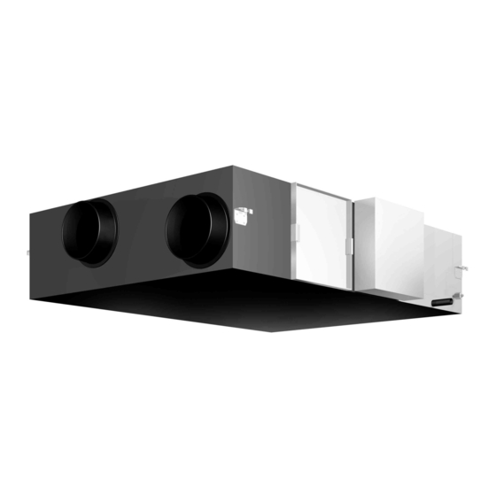
General Information Si71-812 1. General Information Features 1.1.1 External Appearance VKM50GAMV1 VKM50GAV1 VKM80GAMV1 VKM100GAMV1 VKM80GAV1 VKM100GAV1 1.1.2 Model Series Type 1000 DX-Coil and Humidifier VKM50GAMV1 VKM80GAMV1 VKM100GAMV1 DX-Coil VKM50GAV1 VKM80GAV1 VKM100GAV1 These units are applied only for CE regulation. General Constructions... - Page 12 Si71-812 General Information 1.1.3 Nomenclature V K M 50 GA M V1 Ventilation Outdoor Air Treatment Type Mounted Type Nominal Air Flow Rate 50 : 500m /h, 80 : 750m /h, 100 : 950m Major Design Category Moisture (M : With Humidifier Elements, nothing : without Humidifier Elements) Power Supply V1 : 1 Phase : 220-240V, 50Hz 1.1.4 Structures...
- Page 13 General Information Si71-812 1.1.5 Optional Accessories Installation of Optional Accessories (For VKM50GA (GAM) V1, VKM80GA (GAM) V1, VKM100GA (GAM) V1) Air suction/discharge grille (Option) Flexible duct (Option) High efficient filter (Option) Round hood Branch duct (Field supply) (Field supply) Silencer (Option) Duct (Field supply) Thermal insulation material (Field supply)
-
Page 14: Part 2 Product Specification
Si71-812 Part 2 Product Specification 1. Product Specification ................6 1.1 With DX-coil & Humidifier .................6 1.2 With DX-coil .....................8 1.3 Humidifier ....................10 Product Specification... -
Page 15: Product Specification
Product Specification Si71-812 Product Specification With DX-coil & Humidifier Type VKM50GAMV1 VKM80GAMV1 VKM100GAMV1 Refrigerant R410A Power Supply 220-240V, 1ph., 50Hz Air flow rate (m Ultra-high Static pressure (Pa) Air Flow Rate & Air flow rate (m Static Pressure High Static pressure (Pa) (Note 7) Air flow rate (m Static pressure (Pa) - Page 16 Si71-812 Product Specification Note: 1. Cooling and heating capacities are based on the following conditions. Fan is based on High and Ultra- high. The figures in the parenthesis indicate the heat reclaimed from the heat recovery ventilator. When calculating the capacity as indoor units, use the following figures : 7.0kW 2.
-
Page 17: With Dx-Coil
Product Specification Si71-812 With DX-coil Type VKM50GAV1 VKM80GAV1 VKM100GAV1 Refrigerant R410A Power Supply 220-240V, 1ph., 50Hz Air flow rate (m Ultra-high Static pressure (Pa) Air Flow Rate & Air flow rate (m Static Pressure High Static pressure (Pa) (Note 6) - Page 18 Si71-812 Product Specification Note: 1. Cooling and heating capacities are based on the following conditions. Fan is based on High and Ultra- high. The figures in the parenthesis indicate the heat reclaimed from the heat recovery ventilator. When calculating the capacity as indoor units, use the following figures : 3.5kW 2.
-
Page 19: Humidifier
Product Specification Si71-812 Humidifier VKM50GAMV1 VKM80GAMV1 VKM100GAMV1 Humidifier type Natural evaporating type humidifier Porosity plate 120 pcs. Wetted element Porosity plate 60 pcs. Porosity plate 90 pcs. (60×2 pcs.) φ6.4 C1220T (Flare Connection) Water inlet port Water outlet port PT3/4 Supply water pressure kg/cm 0.2 (Min.) ~ 5.0 (Max.) Note:... - Page 20 Si71-812 Part 3 Operation 1. Operation ....................12 1.1 Explanation for Systems.................12 1.2 Features of VKM-GA(M).................15 1.3 Central Control System ................17 1.4 Restrictions to Control System ...............18 1.5 Operation....................20 Operation...
-
Page 21: Part 3 Operation
Operation Si71-812 1. Operation Explanation for Systems Necessary System Construction System Characteristics Accessories • Independent operation of HRV (VKM) is possible. VRV remote HRV (VKM) • VRV remote controller controller can be used. Air conditioner remote controller HRV (VKM) HRV (VKM) •... - Page 22 Si71-812 Operation Necessary System Construction System Characteristics Accessories [Unified ON/OFF Controller] • One controller can control the “ON/OFF” operation of ON/OFF controller 16 groups of units or schedule collectively or individually. timer Indoor unit HRV (VKM) • Up to 8 controllers can be Unified ON/OFF Air conditioner Air conditioner...
- Page 23 Operation Si71-812 Recommended Systems 1. System with a remote sensor connected to each indoor unit On the ceiling chamber system with which generated heat loads are treated in the ceiling space, the suction thermistor (body thermistor) mounted to the indoor unit alone cannot ensure the detection of room temperatures. Consequently, for the indoor unit, in order to ensure the detection of the room temperatures, it is recommended to change to the remote sensor system.
-
Page 24: Features Of Vkm-Ga(M)
Si71-812 Operation Features of VKM-GA(M) Basic control of VKM VKM sucks the air after OA has subjected to total heat exchange with RA, detects the air temperature by means of the thermistor for inlet air into DX-coil (R3T) to make a judgment on operation mode, cooling or heating and exercises the control on the capacity of air heat exchanger. - Page 25 Operation Si71-812 [Points to be noted for VKM-GA(M)] There are following restrictions with VKM-GA(M) model due to its own controlling structure. 1. Stand alone system: No address setting is required because of its automatic addressing function (corresponding to VRV air conditioner PC-board : Master). Because it is under a group control, it is always required to connect to a remote controller.
-
Page 26: Central Control System
Si71-812 Operation Central Control System • When carrying out a central connection, connect the central line to F1 and F2 only on the corresponding VRV indoor unit’s PC-board. Do not connect to F1 and F2 on the ventilation side. ( = Connect to the terminal block X3M.) An image sketch of internal wiring on the ventilation side Terminal block X3M... -
Page 27: Restrictions To Control System
Operation Si71-812 Restrictions to Control System 1.4.1 Do not Give VKM-GA(M) Model a Function to Select Cooling/Heating. (This is because the operation mode switches automatically depending on the outdoor conditions regardless of the indoor temperature when set to "Automatic".) Give a function to select cooling/heating to either one of these. 1.4.2 Caution when Connecting with a VRV System, Heat Recovery Type When bringing the RA (exhaust gas intake) of this unit directly in from the ceiling, connect to a BS unit identical to the VRV indoor unit (master unit), and use group-linked operation. - Page 28 Si71-812 Operation 1.4.3 Caution when Connecting the Indoor Unit Directly to the Duct Follow the indications described below a) When connecting the indoor unit directly to the duct, always use the same system on the indoor unit as with the outdoor unit, perform group-linked operation, and make the direct duct connection settings from the remote controller.
-
Page 29: Operation
This operation manual is for the following systems with standard control. Before initiating operation, contact your Daikin dealer for the operation that corresponds to your system type and mark. If your installation has a customized control system, ask your dealer for the operation that corresponds to your system. - Page 30 Si71-812 Operation Remote Controller and Changeover Switch: Name and Function of Each Switch and Display Remote controller for VRV BRC1A62 13 30 UNIT No. GROUP Remote controller for VKM BRC1D527 (EU only) ∗ Only the items marked with an asterisk ( mark) are explanation relating to the functions and display of the unit.
- Page 31 Operation Si71-812 5. Display “ ” (ventilation/air cleaning) This display shows that the total heat exchange and the air cleaning unit are in operation. (these are optional accessories) 6. Display “ ” (set temperature) This displays the set temperature of the combined air conditioner. It is not displayed when the unit is used as an independent system.
- Page 32 Si71-812 Operation ∗ Display “ ” “ ” “ ” This displays the ventilation mode. (BRC1D527 and so on.) (This is not displayed on the controller BRC1A62) ∗ Ventilation fan mode selector button (available only connecting the HRV unit) This is pressed to switch the fan mode of the HRV unit. ∗...
- Page 33 Operation Si71-812 Explanation for Systems This unit can be made a part of two different systems: as part of the combined operation system used together with VRV SYSTEM Air Conditioners and as the independent system using only the HRV. An operating remote controller is required when using the unit as an independent system. Ask your dealer what kind of system your system is set up for before operation.
- Page 34 Si71-812 Operation The HRV unit cannot be operated independently when the air conditioner is connected to the HRV unit via a duct. When using the HRV unit, set the air conditioner to “fan” mode on weak fan strength. Operation mode display “Ventilation”...
- Page 35 Operation Si71-812 Example 2 : In case of the remote controller “BRC1A62” Display changes as below. When air conditioner and HRV When air conditioner and HRV unit are connected via duct unit are not connected via duct <Operation mode> <Operation mode> VRV : VRV : Cooling mode...
- Page 36 Si71-812 Operation <Conditions> 1. the indoor temperature is higher than the air conditioning setting and 2. the outdoor temperature is lower than the indoor temperature, If the above conditions are not satisfied, reevaluation is made every 60 minutes. 1.5.2 Operation Procedure Cooling, Heating and Fan Only Operation UNIT No.
- Page 37 The unit automatically switches between “ ” and “ ” when it is combined with an air conditioner (Not produced by Daikin) and based on only the information from the HRV unit (indoor and outdoor temperatures) when the HRV unit is operating alone.
- Page 38 Si71-812 Operation Setting the Master Remote Controller UNIT No. GROUP 1,2,3 1,2,3 Remote controller for VKM BRC1D527 (EU only) Remote controller for VRV BRC1A62 • When the system is installed as shown below, it is necessary to designate one of the remote controllers as the master remote controller.
- Page 39 Operation Si71-812 Details and activity of operation • Setting the master remote controller (without the “ ” display) to cooling/heating mode will make slave remote controllers (with the “ ” display) to follow to the mode of the master remote controller. Selection of fan mode is possible, however.
- Page 40 Si71-812 Operation Programming Start and Stop of the System with Timer How to Program and Set the Timer with the Remote Controller “BRC1A62” Remote controller for VRV BRC1A62 • The timer is operated in the following two ways. Programming the stop time “ ”.
- Page 41 Operation Si71-812 Example : Set the time to “8”. ↓ “ ” will display. Starts operation 8 hours after the reservation is complete. The reservation is cancelled after operation starts. • Set the start time while the unit is stopped. •...
- Page 42 Si71-812 Operation Now you must choose between 2 options: 1. CONFIRM AND COPY TO NEXT DAY The schedule timer action programmed for the current day are also valid for the next day: use the “confirm last action and copy actions to next day” function by pressing the “ ”...
- Page 43 Operation Si71-812 Operation...
-
Page 44: Part 4 Maintenance
Si71-812 Part 4 Maintenance 1. Maintenance..................36 1.1 Maintenance for the Air Filter ..............36 1.2 Maintenance for the Heat Exchange Element........38 2. Inspection and Maintenance of the Humidifier ........39 2.1 For VKM-GAMV1 Series ................39 2.2 Replacing the Humidifier Element ............43 Maintenance... -
Page 45: Maintenance
Maintenance Si71-812 Maintenance Maintenance for the Air Filter Caution During operation, never check or clean the HRV. It may cause electrical shock and it is very dangerous to touch the rotating part. Be sure to turn off the OPERATION switch and disconnect the power. - Page 46 Si71-812 Maintenance • Notes Do not wash the air filter with hot water of more than 50°C, as doing so may result in discoloration and/or deformation. • Do not expose the air filter to fire, as doing so may result in burning. •...
-
Page 47: Maintenance For The Heat Exchange Element
Maintenance Si71-812 Maintenance for the Heat Exchange Element CLEANING FREQUENCY AT LEAST ONCE EVERY TWO YEARS (FOR GENERAL OFFICE USE) (CLEAN THE ELEMENT MORE FREQUENTLY IF NECESSARY.) 1. Use a vacuum cleaner to remove dust and foreign objects on the surface of the heat exchange element. -
Page 48: Inspection And Maintenance Of The Humidifier
Si71-812 Inspection and Maintenance of the Humidifier Inspection and Maintenance of the Humidifier For VKM-GAMV1 Series In order to prevent harmful bacteria from generating, do maintenance on humidifying unit portion at the beginning or the end of the heating season. Following working is recommended once a year. - Page 49 Inspection and Maintenance of the Humidifier Si71-812 2.1.2 Inspection of the Feed Water Tank Check for Dirt 1. Remove the maintenance cover. 2. Before cleaning or replacing, remove the supporting stay. (Fig.3) 3. Please loosen a mini valve and drain the water which has accumulated. (Fig.4) 4.
- Page 50 Si71-812 Inspection and Maintenance of the Humidifier Fig. 5 Fig. 6 Hook surely the supporting screw stay on the rail. rail supporting stay Fig. 7 Fig. 8 Maintenance...
- Page 51 Inspection and Maintenance of the Humidifier Si71-812 2.1.3 Inspection of the Drain Pan Please check 1. Remove the maintenance cover. 2. Check whether there is any foreign objects or contamination in drain pan. Carefully check whether there is around the drain outlet. any foreign Wipe off inside of drain pan.
-
Page 52: Replacing The Humidifier Element
Si71-812 Inspection and Maintenance of the Humidifier Replacing the Humidifier Element Replacing the The humidifier element needs to be replaced regularly. The humidifier element should in general be replaced once every three years when supply Humidifier water is soft water, but outside factors (water quality, hard water, etc.) as well as operating Element conditions (24-hour-a-day air conditioning, etc.) may shorten its productive life. - Page 53 Inspection and Maintenance of the Humidifier Si71-812 Maintenance...
-
Page 54: Part 5 Control Functions
Si71-812 Part 5 Control Functions 1. Control Functions ..................46 1.1 Explanation of individual Functions ............46 1.2 Layout of Switches on Printed Circuit Board ..........52 Control Functions... -
Page 55: Control Functions
Control Functions Si71-812 1. Control Functions Explanation of individual Functions 1.1.1 Nighttime Free Cooling Operation Not operation Night Morning Stop Heat Release Heat Release Heat Heat Reserve Reserve Generation of heat with a PC etc. and The load of air conditioner is large and temperature does not fall easily. - Page 56 Si71-812 Control Functions Nighttime Free Cooling Operation <Flow Chart> Nighttime Free Cooling Operating Condition Air-conditioner Operation <STOP> Air-conditioner Operation <RUN> Nighttime Free Cooling Operation <ON> Temp. monitor operation time Standard mode > Lapsed time setup Lapsed time 60hr <2hr, 4hr, 6hr, 8hr> Standby mode <60 Min>...
- Page 57 Control Functions Si71-812 1.1.2 Cold Area Mode Stops or lowers ventilation airflow during defrosting operation and compressor non-operating condition when equipment in heating mode, thus reducing heating load and cold air draft. Operation chart (in heating operation only) By-pass Operation Defrosting operation mode selection or compressor in...
- Page 58 Si71-812 Control Functions 1.1.3 Automatic Selection of Ventilation Mode Unlike the conventional total heat exchanger that only collects the heat on the exhaust air side to the air supply side, the VKM unit monitors the cooling/heating operation mode and the set temperature of air conditioners using microcomputer under the interlock control, and detects indoor and outdoor temperatures under the independent control.
- Page 59 Control Functions Si71-812 1.1.5 Air Conditioner Link Operation Link system enables simultaneous ON/OFF operation of heat reclaim ventilation unit and air conditioner (VRV system, Skyair). 1) 1 group link control Allows simultaneous ON/OFF from remote controller for air conditioner. Allows independent operation of heat reclaim ventilation unit from VRV-system remote controller during interim periods (not possible when direct duct connection is used).
- Page 60 Si71-812 Control Functions 1.1.6 External Damper Operation (FIELD SUPPLY) Explanation of Intake of outdoor air can be prevented when HRV is switched OFF if this damper is incorporated in the system. Functions 1. The total heat exchanger’s main unit print board supplies power for external damper. Essential Wiring 1.
-
Page 61: Layout Of Switches On Printed Circuit Board
Control Functions Si71-812 Layout of Switches on Printed Circuit Board 1.2.1 Printed Circuit Board [A1P~A3P] VKM-GAMV1 2P130159G VKM-GAV1 2P124140C Control Functions... -
Page 62: Part 6 Troubleshooting
Si71-812 Part 6 Troubleshooting 1. Troubleshooting by Remote Controller ..........54 1.1 The INSPECTION / TEST Button............54 1.2 Self-diagnosis by Wired Remote Controller ...........55 2. Troubleshooting ..................56 2.1 Error Code Indication ................56 2.2 Operation of the Remote Controller’s Inspection / Test Operation Button ................57 2.3 Indoor Air Thermistor Error..............58 2.4 Outdoor Air Thermistor Error..............59 2.5 Damper System Error (Alarm)..............60... -
Page 63: Troubleshooting By Remote Controller
Troubleshooting by Remote Controller Si71-812 1. Troubleshooting by Remote Controller The INSPECTION / TEST Button The following modes can be selected by using the [Inspection/Test Operation] button on the remote control. Depress Inspection/Test Operation button for more than 4 seconds. Indoor unit settings can be made Service data can be obtained. -
Page 64: Self-Diagnosis By Wired Remote Controller
Si71-812 Troubleshooting by Remote Controller Self-diagnosis by Wired Remote Controller Explanation If operation stops due to malfunction, the remote controller’s operation LED blinks, and malfunction code is displayed. (Even if stop operation is carried out, malfunction contents are displayed when the inspection mode is entered.) The malfunction code enables you to tell what kind of malfunction caused operation to stop. -
Page 65: Troubleshooting
Troubleshooting Si71-812 2. Troubleshooting Error Code Indication When an abnormality is generated, take necessary measures by referring to displayed error code. After the cause of abnormality is removed, operate equipment and check proper functioning. OPERATION lamp UNIT No. INDOOR UNIT No. in which INSPECTION a malfunction occurs display... -
Page 66: Operation Of The Remote Controller's Inspection / Test Operation Button
Si71-812 Troubleshooting Operation of the Remote Controller’s Inspection / Test Operation Button Unit Malfunction code Inspection Normal display (No display) Malfunction code blinks when a malfunction occurs. Inspection/test Push the button. operation Example of capacity code display Example model Display Unit FXCQ25 0 7 1... -
Page 67: Indoor Air Thermistor Error
Troubleshooting Si71-812 Indoor Air Thermistor Error Remote Error Code Inspection — Unit No. Controller LCD Display LED Indication Remote Controller Main Unit Error Detection Temperature detected by inside air temperature sensor is used to detect errors. Method Error Generating When value detected by inside air temperature sensor is -40ºC or below (open circuit) or 70ºC or higher (short-circuit). -
Page 68: Outdoor Air Thermistor Error
Si71-812 Troubleshooting Outdoor Air Thermistor Error Remote Error Code Inspection — Unit No. Controller LCD Display LED Indication Remote Controller Main Unit Error Detection Temperature detected by outside air temperature sensor is used to detect errors. Method Error Generating When value detected by outside air temperature sensor is -40ºC or below (open circuit) or 70ºC or higher (short-circuit). -
Page 69: Damper System Error (Alarm)
Troubleshooting Si71-812 Damper System Error (Alarm) Remote Error Code Inspection — Unit No. Controller LCD Display LED Indication Remote Controller Main Unit Error Detection Measurement of damper motor limit ON/OFF time. Method Error Generating When damper motor limit switch 1 (or 2) remains ON (or OFF) for more than a certain time duration after ventilation mode is changed. -
Page 70: Damper System Error (Alarm)
Si71-812 Troubleshooting Damper System Error (Alarm) Remote Error Code Inspection Unit No. Controller LCD Display LED Indication Remote Controller Main Unit Error Detection Measurement of damper motor limit switch ON/OFF time and temperatures detected by outdoor and indoor air thermistor. Method Error Generating When damper system error (alarm) and indoor (or outdoor) thermistor error are generated at... -
Page 71: A1" Indoor Unit: Pc Board Defect
Troubleshooting Si71-812 “ ” Indoor Unit: PC Board Defect Remote Controller Display Applicable All indoor unit models Models Method of Check data from E²PROM. Malfunction Detection Malfunction When data could not be correctly received from the E²PROM E²PROM : Type of nonvolatile memory. Maintains memory contents even when the power Decision supply is turned off. -
Page 72: Electronic Expansion Valve (20E)
Si71-812 Troubleshooting “ ” Indoor Unit: Malfunction of Moving Part of Electronic Expansion Valve (20E) Remote Controller Display Applicable All indoor unit models Models Method of Detection by failure of signal for detecting number of turns to come from the fan motor Malfunction Detection Malfunction... -
Page 73: C4" Indoor Unit: Malfunction Of Thermistor (R4T) For Heat Exchanger
Troubleshooting Si71-812 “ ” Indoor Unit: Malfunction of Thermistor (R4T) for Heat Exchanger Remote Controller Display Applicable All indoor unit models Models Method of Malfunction detection is carried out by temperature detected by heat exchanger thermistor. Malfunction Detection Malfunction When the heat exchanger thermistor becomes disconnected or shorted while the unit is running. Decision Conditions Supposed... -
Page 74: C5" Indoor Unit: Malfunction Of Thermistor (R5T) For Gas Pipes
Si71-812 Troubleshooting “ ” Indoor Unit: Malfunction of Thermistor (R5T) for Gas 2.10 Pipes Remote Controller Display Applicable All indoor unit models Models Method of Malfunction detection is carried out by temperature detected by gas pipe thermistor. Malfunction Detection Malfunction When the gas pipe thermistor becomes disconnected or shorted while the unit is running. -
Page 75: C9" Indoor Unit: Malfunction Of Thermistor (R3T) For Suction Air
Troubleshooting Si71-812 “ ” Indoor Unit: Malfunction of Thermistor (R3T) for 2.11 Suction Air Remote Controller Display Applicable AII indoor unit models Models Method of Malfunction detection is carried out by temperature detected by suction air temperature thermistor. Malfunction Detection Malfunction When the suction air temperature thermistor becomes disconnected or shorted while the unit is running. -
Page 76: U3" Check Operation Not Executed
Si71-812 Troubleshooting “ ” Check Operation not Executed 2.12 Remote Controller Display Applicable Models Method of Check operation is executed or not Malfunction Detection Malfunction Malfunction is decided when the unit starts operation without check operation. Decision Conditions Supposed Check operation is not executed. Causes Troubleshooting Be sure to turn off power switch before connect or disconnect connector,... -
Page 77: Dedicated Lcd Remote Controller
Troubleshooting Si71-812 2.13 Dedicated LCD Remote Controller Error Detection When “ ” remains on remote controller display. Method Error Generating Conditions Possible Causes Master-slave setting of remote controller Remote controller PC board assembly error Main unit PC board assembly error Troubleshooting Be sure to turn off power switch before connect or disconnect connector, Caution... -
Page 78: Data Transmission Error (Between Lcd Remote Controller And Main Unit)
Si71-812 Troubleshooting 2.14 Data Transmission Error (between LCD Remote Controller and Main Unit) Remote Error Code Inspection Unit No. Controller LCD Display LED Indication Remote Controller Main Unit Error Detection Microcomputer checks if data is transmitted properly between main unit and remote controller. Method Error Generating When data transmission is not performed correctly for a certain time period. -
Page 79: U5" Malfunction Of Transmission Between Remote Controller And Indoor Unit
Troubleshooting Si71-812 “ ” Malfunction of Transmission between Remote 2.15 Controller and Indoor Unit Remote Controller Display Applicable All models of indoor units Models Method of In case of controlling with 2-remote controller, check the system using microcomputer is signal transmission between indoor unit and remote controller (main and sub) is normal. -
Page 80: U8" Malfunction Of Transmission Between Master And Slave Remote Controllers
Si71-812 Troubleshooting “ ” Malfunction of Transmission between Master and 2.16 Slave Remote Controllers Remote Controller Display Applicable All models of indoor units Models Method of In case of controlling with 2-remote controller, check the system using microcomputer if signal transmission between indoor unit and remote controller (main and sub) is normal. -
Page 81: Ua" Excessive Number Of Indoor Units
Troubleshooting Si71-812 “ ” Excessive Number of Indoor Units 2.17 Remote Controller Display Applicable All models of indoor unit Models Method of Malfunction Detection Malfunction Decision Conditions Supposed Excess of connected indoor units Defect of outdoor unit PC board (A1P) Causes Mismatching of the refrigerant type of indoor and outdoor unit. -
Page 82: Uc" Address Duplication Of Central Remote Controller
Si71-812 Troubleshooting “ ” Address Duplication of Central Remote Controller 2.18 Remote Controller Display Applicable All models of indoor unit Centralized controller Models Method of Malfunction Detection Malfunction Decision Conditions Supposed Address duplication of centralized remote controller Defect of indoor unit PC board Causes Troubleshooting Be sure to turn off power switch before connect or disconnect connector,... -
Page 83: Ue" Malfunction Of Transmission Between Central Remote Controller And Indoor Unit
Troubleshooting Si71-812 “ ” Malfunction of Transmission between Central 2.19 Remote Controller and Indoor Unit Remote Controller Display Applicable All models of indoor units Centralized controller Models Method of Microcomputer checks if transmission between indoor unit and centralized remote controller is normal. - Page 84 Si71-812 Troubleshooting Troubleshooting Be sure to turn off power switch before connect or disconnect connector, Caution or parts damage may be occurred. an indoor unit once connected been remove Reset power supply or its address simultaneously for all optional changed? controllers for centralized control.
-
Page 85: Ue" Malfunction Of Transmission Between Central Remote Controller And Indoor Unit
Troubleshooting Si71-812 “ ” Malfunction of Transmission between Central 2.20 Remote Controller and Indoor Unit Remote Controller Display Applicable All models of indoor units Models Method of Microcomputer checks if transmission between indoor unit and central remote controller is normal. Malfunction Detection Malfunction... -
Page 86: Main Unit Pc Board Assembly
Si71-812 Troubleshooting 2.21 Main Unit PC Board Assembly Error Detection Check microcomputer operation monitor. Method Error Generating When main unit PC board assembly does not operate. When communication circuit errors. Conditions Possible Causes Fuse (excess current) Power transformer Noise Main unit PC board Troubleshooting Be sure to turn off power switch before connect or disconnect connector, Caution... -
Page 87: Thermistor
Troubleshooting Si71-812 2.22 Thermistor Error Detection Remove thermistor and check resistance with tester. Method Error Generating Conditions Possible Causes Faulty thermistor Broken wire Faulty control PC board Faulty contact in connector Troubleshooting Be sure to turn off power switch before connect or disconnect connector, Caution or parts damage may be occurred. - Page 88 Si71-812 Troubleshooting For Thermistor of Indoor Air R1T For Thermistor of Outdoor Air R2T Indoor unit For air suction Outdoor unit For outdoor air For liquid pipe For coil For gas pipe For suction pipe For Receiver gas pipe R5T (kΩ) T°C T°C...
-
Page 89: Power Transformer
Troubleshooting Si71-812 2.23 Power Transformer Error Detection Check resistance and voltage with tester, and insulation resistance with megger. Method Error Generating Conditions Possible Causes Troubleshooting Be sure to turn off power switch before connect or disconnect connector, Caution or parts damage may be occurred. Check resistance of primary side of transformer. -
Page 90: Damper Motor
Si71-812 Troubleshooting 2.24 Damper Motor Error Detection Check damper motor and limit switch when damper motor does not operate. Method Error Generating Conditions Possible Causes Troubleshooting Be sure to turn off power switch before connect or disconnect connector, Caution or parts damage may be occurred. Place tester probes at connectors of limit switch, and check... - Page 91 Troubleshooting Si71-812 Troubleshooting...
-
Page 92: Part 7 Field Setting
Si71-812 Part 7 Field Setting 1. Field Setting ..................84 1.1 Field Setting and Test Run..............84 Field Setting... -
Page 93: Field Setting
Field Setting Si71-812 Field Setting Field Setting and Test Run 1.1.1 Perform Field Settings with the Remote Controller (1) Make sure the Electric Parts Box Lids are closed on the Indoor and Outdoor Units. (2) Depending on the Type of Installation, make the Field Settings from the Remote Controller after the Power is turned on, following the “Field Settings”... - Page 94 Si71-812 Field Setting <Example> When adjusting the ventilation air flow to low setting in the group setting mode, enter the mode No., “19” FIRST CODE NO., “0” and SECOND CODE NO., “01”. Settings and setting numbers FIRST SECOND CORD NO. Mode Description of setting CORD...
- Page 95 Field Setting Si71-812 5. When “Filter cleaning time setting” or “Night-purge operation setting” is changed, explain set contents to the customer. 6. See below for details on the settings for cold areas. HRV fan Air conditioner Fan Heating thermo off Operation –...
- Page 96 Si71-812 Field Setting 1.1.2 Perform a Test Run according to the Outdoor Unit’s Installation Manual 1. Make sure the electric parts box of the unit is closed before turning on power. 2. Make a test run following the operation manual of the outdoor unit. The operation lamp of the remote controller will flash when an malfunction occurs.
- Page 97 Field Setting Si71-812 1.1.3 Next, Run the Humidifier <VKM-GAMV1 series only> 1. Check that the water supply piping is connected securely. 2. Open the water supply shut-off valve. (No water will be supplied at this time.) 3. Run the HRV unit in heating mode. (See the operating manual included with the indoor unit for details on how to run the unit in heating mode.) The water supply will start and the humidifier will begin operation.
- Page 98 Si71-812 Part 8 Appendix 1. Appendix ....................90 1.1 Wiring Diagram..................90 1.2 List of Electrical and Functional Parts ............92 2. Piping Diagram..................93 Appendix...
-
Page 99: Part 8 Appendix
Appendix Si71-812 1. Appendix Wiring Diagram VKM50GAMV1 VKM80GAMV1 VKM100GAMV1 Appendix... - Page 100 Si71-812 Appendix VKM50GAV1 VKM80GAV1 VKM100GAV1 Appendix...
-
Page 101: List Of Electrical And Functional Parts
Appendix Si71-812 List of Electrical and Functional Parts Model Parts Name Symbol Remark 50GAMV1 80GAMV1 100GAMV1 50GAV1 80GAV1 100GAV1 Remote Wired Remote BRC1A61, BRC1D527 Option Controller Controller Fan Motor AC220V 280W 4P Motors MG8(3P145772-2) Damper Motor AC220~240V ST8601-15C φ4 L1000 Thermistor (Indoor Air) 20kΩ... -
Page 102: Piping Diagram
Si71-812 Piping Diagram Piping Diagram Humidifier Elements Gas piping connection port (Pipe guage φ12.7) DX-Coil Liquid piping connection port (Pipe guage φ6.4) Electronic Filter Filter expansion valve Damper Air supply fan Damper Heat exchanger elements Moter Exhaust fan R1T: Thermistor for indoor air R2T: Thermistor for outdoor air R3T: Thermistor for inlet air into DX-coil R4T: Thermistor for liquid line temperature... - Page 103 Piping Diagram Si71-812 Appendix...
-
Page 104: Index
Si71-812 Index Symbols "A1" Indoor Unit Heat Exchange Element ........38 PC Board Defect ..........62 "A9" Indoor Unit Malfunction of Moving Part of Indoor Air Thermistor Error ........58 Electronic Expansion Valve (20E) ..63 Inspection and Maintenance of the Humidifier ..39 "C4"... - Page 105 Si71-812 Index...
-
Page 106: Drawings & Flow Charts
VKM100GAMV1 ............2 Independent Operation ........12 VKM100GAV1 ............2 Recommended Systems .........14 VKM50GAMV1 ............2 Simultaneous Operation of Multiple Units ..12 VKM50GAV1 ............2 Standard System ..........12 VKM80GAMV1 ............2 Zone Control System ........13 VKM80GAV1 ............2 Field Setting ............84 Wiring Diagram ............. - Page 107 Daikin Industries, Ltd.’s products are manufactured for export to numerous countries throughout the Warning world. Daikin Industries, Ltd. does not have control over which products are exported to and used in a particular country. Prior to purchase, please therefore confirm with your local authorised importer, distributor and/or retailer whether this product conforms to the applicable standards, and is suitable for use, in the region where the product will be used.
Need help?
Do you have a question about the VKM50GAV1 and is the answer not in the manual?
Questions and answers