Table of Contents
Advertisement
Advertisement
Table of Contents

Related Manuals for Milesight Technology MS-C2981-PB


Summary of Contents for Milesight Technology MS-C2981-PB
- Page 1 Network Camera User Manual V7.14...
- Page 2 This manual is applicable to the Milesight H.265 Network Camera, series shown as follows, except where otherwise indicated. Milesight H.265 Network Camera Type Megapixel Mini Dome Network Camera MS-C2981-PB MS-C5381-PB — — IR Mini Dome Network Camera MS-C2983-PB MS-C5383-PB —...
- Page 3 This Manual explains how to use and manage Milesight network cameras on your network. Previous experience of networking will be of use when using the products. Please read this manual carefully before operation and retain it for future reference. This manual may contain several technically incorrect places or printing errors, and the content is subject to change without notice.
- Page 4 Source with DC 12V or PoE Please make sure the plug is firmly inserted into the power socket When the product is installed on a wall or ceiling, the device should be firmly fixed If the product does not work properly, please contact your dealer. Never attempt to disassemble the camera by yourself Cautions ...
-
Page 5: Table Of Contents
Table of Contents Chapter I Product Description......................1 1.1 Product Overview........................1 1.2 Key Features..........................1 1.3 Hardware Overview......................... 2 1.4 How to Connect to Alarm Interface..................16 1.5 How to Connect the Water-proof Connector................16 1.6 System Requirements......................17 Chapter II Network Connection......................18 2.1 Setting the Camera over the LAN.................. -
Page 6: Chapter I Product Description
Chapter I Product Description 1.1 Product Overview Milesight provides a consistent range of cost-effective and reliable network cameras to fully meet your requirements. Based on embedded Linux operating system, Milesight network cameras could be easily accessed and managed either locally or remotely with great reliability. With built-in high-performance DSP video processing modules, the cameras pride on low power consumption and high stability. -
Page 7: Hardware Overview
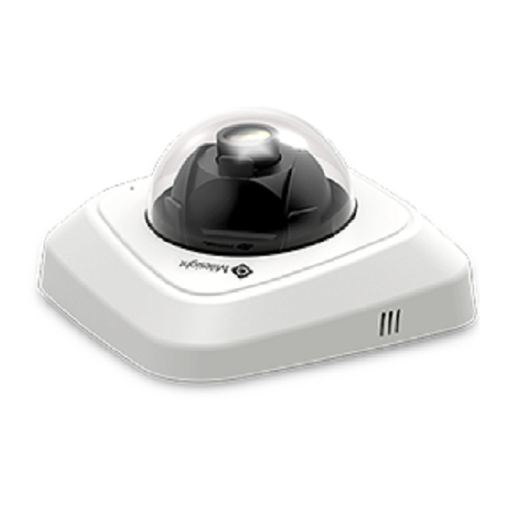
1.3 Hardware Overview 1. Mini Dome Network Camera Press Button Ethernet Port (PoE) Lens Error LED Indicator Power LED Indicator microSD/SDHC/SDXC Card Slot Reset Figure 1-3-1 Mini Dome Network Camera Note: 1) Error LED Indicator: Error LED Indicator is on when the device starts up or runs error. 2) Reset Button: Press “Reset”... - Page 8 2. IR Mini Dome Network Camera Light Sensor Lens Microphone Reset microSD/SDHC/SDXC Card Slot Power LED Indicator Error LED Indicator Ethernet Port (PoE) Press Button Figure 1-3-2 IR Mini Dome Network Camera Note: 1) Error LED Indicator: Error LED Indicator is on when the device starts up or runs error. 2) Reset Button: Press “Reset”...
- Page 9 3. Vandal-proof Mini Dome Network Camera IR LEDs Light Sensor Microphone Screw Lens microSD/SDHC/SDXC Ethernet Port (PoE) Card Slot Reset Power and System LED Indicator Figure 1-3-3 Vandal-proof Mini Dome Network Camera Note: 1) Error LED Indicator: Error LED Indicator is on when the device starts up or runs error. 2) Reset Button: Press “Reset”...
- Page 10 4. Weather-proof Mini Dome Network Camera Figure 1-3-4 Weather-proof Mini Dome Network Camera Note: 1) Reset Button: Press “Reset” button for 5 seconds, then the device will be restored to factory default. 2) Only PoE is available for power supply.
- Page 11 5. AF Motorized Mini Dome Network Camera Figure 1-3-5 AF Motorized Mini Dome Network Camera Note: 1) Reset Button: Press “Reset” button for 5 seconds, then the device will be restored to factory default. 2) DC 12V and PoE are available for power supply.
- Page 12 6. Mini Bullet Network Camera IR LEDs Lens Light Sensor Ethernet Port (PoE) microSD/SDHC/SDXC Card Slot Reset Button Figure 1-3-6 Mini Bullet Network Camera Note: 1) Only PoE is available for power supply. 2) Reset Button: Press “Reset” button for 5 seconds, then the device will be restored to factory default.
- Page 13 7. Vandal-proof Mini Bullet Network Camera Figure 1-3-7 Vandal-proof Mini Bullet Network Camera Note: 1) Only PoE is available for power supply. 2) Reset Button: Press “Reset” button for 5 seconds, then the device will be restored to factory default.
- Page 14 8. (Vandal-proof) Motorized Mini Bullet Network Camera Ethernet Port (PoE) Figure 1-3-8 (Vandal-proof) Motorized Mini Bullet Network Camera Note: 1) DC 12V and PoE are available for power supply. 2) Reset Button: Press “Reset” button for 5 seconds, then the device will be restored to factory default.
- Page 15 9. 180°Panoramic Mini Bullet Network Camera Note: 1) PoE is available for power supply. 2) Reset Button: Press “Reset” button for 5 seconds, then the device will be restored to factory default.
- Page 16 10. (12x AF) Motorized Pro Bullet Network Camera microSD/SDHC/SDXC Card Slot Reset PTFE Membrane IR LEDs Lens Light Sensor Figure 1-3-9 (12x AF) Motorized Pro Bullet Network Camera Note: 3) DC 12V and PoE are available for power supply. 4) Reset Button: Press “Reset” button for 5 seconds, then the device will be restored to factory default.
- Page 17 Ethernet Port (PoE) Alarm/Audio DC 12V Figure 1-3-10 Motorized Pro Bullet Network Camera(Version A) Audio In/Out Ethernet Port (PoE) Alarm In/Out DC 12V Figure 1-3-11 Motorized Pro Bullet Network Camera(Version B)
- Page 18 11. Motorized Pro Dome Network Camera Microphone Lens Light Sensor IR LEDs Reset microSD/SDHC/SDXC Card Slot Figure 1-3-12 Motorized Pro Dome Network Camera Note: 1) Reset Button: Press “Reset” button for 5 seconds, then the device will be restored to factory default.
- Page 19 DC 12V Alarm In/Out & Audio Out/DC 12V Ethernet Port (PoE) Water-proof Connector Figure 1-3-13 Motorized Pro Dome Network Camera multiple interface Here is one equipped cable for multiple interface usage: Ethernet Port DC 12V (PoE) Alarm In/Out Audio Out Alarm In/Out &...
- Page 20 12. (LPR) (ABF) Pro Box Network Camera Figure 1-3-15 (ABF) Pro Box Network Camera Note: Reset Button: Press “Reset” button for 5 seconds, then the device will be restored to factory default. DC 12V and PoE are available for power supply.
-
Page 21: How To Connect To Alarm Interface
1.4 How to Connect to Alarm Interface External interface of camera is as the following, you can refer to the picture to install the external alarm device: PIN1: Alarm Output NC/NO 24V DC 1A PIN2: Alarm Output NC/NO 24V DC 1A PIN3: Alarm Input NC/NO ≤12V PIN4: Alarm Input NC/NO ≤12V 1.5 How to Connect the Water-proof Connector... -
Page 22: System Requirements
1.6 System Requirements Operating System: Windows XP/Vista/7/8/10/Server 2000/Server 2008 CPU: 1.66GHz or higher RAM: 1G or higher Graphic memory: 128MB or more Internet protocol: TCP/IP (IPv4/IPv6) Web Browsers: Internet Explorer 8.0 and above version, Mozilla Firefox, Google Chrome and Safari. -
Page 23: Chapter Ii Network Connection
Chapter II Network Connection 2.1 Setting the Camera over the LAN Connecting the camera to a switch or a router is the most common connection method. The camera must be assigned an IP address that is compatible with its LAN. 2.1.1 Connect the Camera to the PC Directly In this method, only the computer connected to the camera will be able to view the camera. - Page 24 Step5: Configure the DDNS settings in the setting interface of the router; Step6: Visit the camera via the domain name. Figure 2-2 Connect the network camera via a router using dynamic IP...
-
Page 25: Chapter Iii Accessing The Network Camera
Chapter III Accessing the Network Camera The camera must be assigned an IP address to be accessible. 3.1 Assigning An IP Address The Network Camera must be assigned an IP address to be accessible. The default IP address of Milesight Network Camera is 192.168.5.190. You can either change the IP address of the camera via Smart Tools or browser. - Page 26 Step3: Select a camera or multiple cameras according to the MAC addresses; Select single camera Select multiple cameras Step4: If the selected camera shows "Active" in the status bar, you can directly type the User Name and Password (Camera with version lower than 4x.7.0.69 is using admin/ms1234 by default), change the IP address or other network values, and then click “Modify”...
- Page 27 If the selected camera shows "Inactive" in the status bar(Camera with version V4x.7.0.69 or above), click to set the password when using it for the first time. You can also set the security questions when activating the camera in case that you forget the password(You can reset the password by answering three security questions correctly).
-
Page 28: Assign An Ip Address Via Browser
Step5: Change the IP address successfully; Step6: By double clicking the selected camera or the browser of interested camera, you can access the camera via web browser directly. The Internet Explorer window will pop up. More usage of Smart Tools, please refer to the Smart Tools User Manual. 3.1.2 Assign An IP Address via Browser If the network segment of the computer and that of the camera are different, please follow the... - Page 29 steps to change the IP address: Step1: Change the IP address of computer to 192.168.5.0 segment, here are two ways as below: Start Control Panel Network and Internet Connection Network Connection Local Area Connection, and double click it. (Refer to Figure 3-1-8); Figure 3-1-8 Setting Network Segment IP Address of Computer Click “Advanced”, and then click “IP settings”...
- Page 30 Step3: If the camera’s firmware version is lower than V4x.7.0.69, it will directly display the login page, enter the user name and password when the LOGIN page appears; Default user name: admin Default password: ms1234 If the camera’s firmware version is V4x.7.0.69 or above, you need to set the password first when using it for the first time.
-
Page 31: Accessing From The Web Browser
Step5: Change the IP address or other network values. Then click “Save” button; Step6: The change of default IP address is completed. 3.2 Accessing from the Web Browser The camera can be used with the most standard operating systems and browsers. The recommended browsers are Internet Explorer, Firefox, Chrome, Microsoft Edge, Safari. - Page 32 If IE9 or higher version browser is used, it is suggested that the Milesight camera web link should be added as a trusted site. See the instructions as follows: Step1: Start the IE9 or higher version browser, and select “Tools” “Internet Options”; Step2: Select “Security”...
-
Page 33: Access Without Plugin
Step4: Enter the IP address. After logging on network camera’s web GUI successfully, user is allowed to view live video as follows. 3.2.2 Access without Plugin You can preview the video on the browser without plugin in Plugin-Free mode. Currently Plugin-Free mode is supported in Chrome and Firefox browser for Windows system, MAC system and Android system. - Page 34 Step2: Click “ ” icon in the lower left corner of the webpage, you can refer to Plugin-Free Mode instruction below. Step3: Input the URL in address bar: chrome://flags/#enable-webassembly-threads You will enter the webpage shown below.
- Page 35 Step4: Set 2 flags to True status and reboot browser: --WebAssembly threads support. --Experimental enabled SharedArrayBuffer support in JavaScript Step5: Then you can preview the video without plugin by selecting Plugin-Free mode in Live View interface.
- Page 36 It supports previewing the video in Live View and other setting interfaces. (2) On Firefox browser Step1: Access camera via Firefox browser. Step2: Click “ ” icon in the lower left corner of the webpage, you can refer to Plugin-Free Mode instruction below.
- Page 37 Step3: Input the URL in address bar: about:config And accept the requiring. You will enter the webpage shown below.
-
Page 38: Accessing From Milesight Vms (Video Management Software)
Step4: Set 2 flags to Enabled status and reboot browser: --javascript.options.wasm. --javascript.options.shared_memory. Step5: Then you can preview the video without plugin by selecting Plugin-Free mode. It supports previewing the video in Live View, Playback and other setting interfaces. 3.3 Accessing from Milesight VMS (Video Management Software) Milesight VMS(ONVIF compatible) is a handy and reliable application designed to work with network cameras in order to provide video surveillance, recording settings and event management functions. - Page 39 Milesight VMS Live View...
-
Page 40: Chapter Iv System Operation Guide
Chapter IV System Operation Guide 4.1 Live Video After logging in the network camera web GUI successfully, user is allowed to view live video as follows. Table 4-1-1 Description of the buttons Parameter Description Brightness: Adjust the Brightness of the scene Contrast: Adjust the color and light contrast Saturation: Adjust the Saturation of the image.Higher Saturation makes colors appear more "pure"... - Page 41 (Chrome version 44 or below); need to install the component to display the view; MJPEG: Support to display the view on Firefox, Safari, Chrome (Chrome version 45 or above); (NOTE: IE choose Web Components mode for default, in this case, it will not show the options) TCP: More reliable connection;...
-
Page 42: Playback
Adjust iris automatically if check this box ( Only work when your camera is equipped with P-Iris) Start/Stop live view Click to capture the current image and save to the configured path. The default path is Capture C:VMS\+-1\ IMAGE-MANUAL Click to start recording video and save to the configured path. - Page 43 Step2: Click the date button, choose the date when date window pops up; Note: 1) The date with bright red means current date; one with a dark red number and white background means weekend day; one with a dark red number and blue background means that the date is selected now.
-
Page 44: Local Settings
Time Narrow/Expand Start/Stop Recording Snapshot Zoom On/Off Full Screen Note: 1) Drag the progress bar with the mouse to locate the exact playback point. You can also input the time and click to locate the playback point in the Set Playback Time filed. You can also click to zoom out/in the progress bar. - Page 45 Primary Stream Settings Secondary Stream Settings Tertiary Stream Settings Table 4-4-1 Description of the buttons Parameters Function Introduction There are differences for the camera with “-A” and “-B” Video Codec -A: H.264/MJPEG are available -B: H.265/H.264/MJPEG are available...
- Page 46 Options include 8M(3840×2160), 6M(3072×2048), 5M(2592*1944), 5M(2560*1920), 5M(2560*1440), 4M(2592*1520), 3M(2304*1296), 3M(2048*1536), 1080P(1920*1080), 2M(1600 *1200), 1.3M(1280*960), 720P(1280*720), D1(704*576). Frame Size For Secondary Stream, it includes 704*576, 640*480, 640*360, 352*288, 320*240, 320*192, 320*176. For Tertiary Stream, it include 1920*1080, 1280*720, 704*576, 640*480, 640*360, 352*288, 320*240, 320*192, 320*176. Maximum Frame Rate Maximum refresh frame rate of per second Transmitting bits of data per second, this item is optional only if you select the...
-
Page 47: Image
4.4.2 Image Display information, enhancement of image and Day/Night setting can be set in this module. OSD (On Screen Display) content and video time can be displayed to rich the image information. Display Table 4-4-2 Description of the buttons Parameters Function Introduction Power Line Frequency 60HZ flicker for NTSC mode and 50HZ flicker for PAL mode... - Page 48 object distance. Also, the Low Beam and High Beam's brightness can be adjusted manually or automatically on the basis of the Zoom ratio. Moreover, with the IR anti-reflection panel, the infrared light transmittance is highly increased. Support to set the strength of the IR to Auto Mode or Customize to achieve the best effect.
- Page 49 Table 4-4-3 Description of the buttons Parameters Function Introduction There is an option to turn On/Off the IR LED. IR Balance Mode IR Balance Mode would avoid the problem of overexposure and darkness, and the IR LED will change according to the actual illumination. To restore white objects, removed color distortion caused by the light of the environment Auto White Balance: This option will automatically enable the White...
- Page 50 Centre: This option will automatically add an inclusive region in the middle of the window and give the necessary light compensation This function which can capture and display both bright and dark areas in the same frame enables details of objects in both bright and dark areas to be visible.
- Page 51 3) You can customize the schedule to enable/disable BLC/WDR/HLC mode. 4) WDR/HLC has higher priority than exposure settings at the same time frame. 5) Defog Image. 6) HLC Image.
- Page 52 Day/Night Mode Table 4-4-4 Description of the buttons Parameters Function Introduction Exposure Level Level 0~10 are available to meet your need Minimum Shutter is the same as Maximum Exposure Time. Set the minimum Minimum Shutter Shutter to 1~1/100000 Maximum Shutter is the same as Minimum Exposure Time. Set the maximum Maximum Shutter Shutter to 1~1/100000 IR-CUT Latency...
- Page 53 On Screen Display(OSD) Table 4-4-5 Description of the buttons Parameters Function Introduction Video Stream Enable to set OSD for primary stream and secondary stream Font Size Smallest/Small/Medium/Large/Largest/Auto are available for title and date Font Color Enable to set different color for title and date Show Video Title Check the checkbox to show video title Video Title...
- Page 54 Privacy Mask Privacy mask enables to cover certain areas on the live video to prevent certain spots in the surveillance area from being viewed and recorded. You can set 8 mask areas at most. Table 4-4-6 Description of the buttons Parameters Function Introduction Enable...
-
Page 55: Audio
Table 4-4-7 Description of the buttons Parameters Function Introduction Enable Check the checkbox to enable the ROI function Clear All Clear all areas you drew before Video Stream Choose the Video Stream Note: You can set a low bit rate. For example, you can set a bit rate with 512Kbps and a resolution with 1080P, then you can see the image quality of ROI is more clear and fluent than the other region. - Page 56 Table 4-4-8 Description of the buttons Parameters Function Introduction Enable Audio Check on the checkbox to enable audio feature Denoise: Set it as On/Off. When you set the function on, the noise detected can be filtered Encoding: G711-ULaw, G711-ALaw and AAC LC are available Audio Input Sample Rate: There are 8KHz/16KHz two options Input Gain: Input audio gain level, 0-100...
-
Page 57: Network
Note: 1) The Audio mode and Audio Output are only for certain modules. 2) Only support ‘.wav’ audio files with codec type PCM/PCMU/PCMA, 64kbps or 128 kbps and no more than 500k. 4.4.4 Network TCP/IP Table 4-4-9 Description of the buttons Parameters Function Introduction Get IPv4 Address... - Page 58 IPv4 Address: An address that used to identify a network camera on the network IPv4 Subnet Mask: It is used to identify the subnet where the network camera is located IPv4 Default Gateway: The default router address Preferred DNS Server: The DNS Server translates the domain name to IP Use fixed IP address address IPv6 Mode: Choose different mode for IPv6: Manual/Route Advertisement/...
- Page 59 HTTP Settings Upload and set the SSL certificate . HTTP URL are as below: Stream Main Stream http://username:password@IP:port/ipcam/mjpeg.cgi Secondary Stream http://username:password@IP:port/ipcam/mjpegcif.cgi Tertiary Stream http://username:password@IP:port/ipcam/mjpegthird.cgi Note: You need to change the codec type of streams to MJPEG except the main stream of H.264 cameras whose models with “-A”.
- Page 60 Main Stream rtsp://username:password@IP:port/main Secondary Stream rtsp://username:password@IP:port/sub Tertiary Stream rtsp://username:password@IP:port/third Note: 1) Get the format of RTSP URL by clicking “ ”on the right side of RTSP Port. 2) Get the playback tip by clicking “ ”on the right side of Playback Port. 3) DSCP refers to the Differentiated Service Code Point;...
- Page 61 Enable Port Mapping Check the checkbox to enable the Port Mapping Name The name of the device detected online can be edited Auto: Automatically obtain the corresponding HTTP and RTSP port, without any settings Type Manual: Need to manually set the appropriate HTTP port and RTSP Port. When choose Manual, you can customize the value of the port number by yourself DDNS DDNS allows you to access the camera via domain names instead of IP address.
- Page 62 Note: 1)Please do the Port Forwarding of HTTP Port and RTSP Port before you use Milesight DDNS. 2)Make sure that the internal and the external port number of RTSP are the same. Email Alarm video files can be sent to specific mail account through SMTP server. You must configure the email settings correctly before using it.
- Page 63 Alarm video files can be sent to specific FTP server. You must configure the FTP settings correctly before using it. Table 4-4-15 Description of the buttons Parameters Function Introduction Server Address FTP server address Server Port The port of the FTP server. Generally it is 21 User Name User name used to log in to the FTP sever Password...
- Page 64 If you choose to customize the alarm action file name, YYYY-MM-DD/ Video File Name MM-DD-YYYY/ DD-MM-YYYY/ Add prefix are available. If you choose to customize the alarm action file name, YYYY-MM-DD/ Image File Name MM-DD-YYYY/ DD-MM-YYYY/ Add prefix are available. Timing Snapshot File Default(YYYY-MM-DD) /MM-DD-YYYY/ DD-MM-YYYY/ Add prefix/ Overwrite with Name...
- Page 65 Note: 1) The obtained IP address is dynamically assigned via PPPoE, so the IP address always changes after rebooting the camera. To solve the inconvenience of the dynamic IP, you need to get a domain name from the DDNS provider (e.g. DynDns.com). 2) The user name and password should be assigned by your ISP.
-
Page 66: Date&Time
Level of Security There are three levels available: (auth, priv), (auth, no priv) and (no auth, no priv) Write Security Name Input the name of Write Security Community Level of Security There are three levels available: (auth, priv), (auth, no priv) and (no auth, no priv) SNMP Port The port of SNMP, the default is 161 Note:... -
Page 67: Advanced Settings
Current System Time Current date&time of the system Set the System Time Table 4-4-17 Description of the buttons Parameters Function Introduction Time Zone Choose a time zone for your location Daylight Saving time Enable the daylight saving time NTP Sync Regularly update your time according to the interval time Synchronize with Synchronize the time with your computer... - Page 68 Table 4-5-1 Description of the buttons Parameters Function Introduction Enable Motion Check the checkbox to enable Motion Detection function Detection Normal and Compatible are available for the option. If the setting of motion Onvif Motion region of the third-party software is different from ours, please set this option to ActiveCells Settings Compatible.
- Page 69 Upload Via FTP Upload the recording files via FTP Upload Via SMTP Upload the files via SMTP If the camera equips with External Output, you can enable the action after External Output configuring the trigger duration If the camera equips with Speaker, you can enable the action after configuring the Play Audio audio speaker If the camera equips with Buzzer, you can check the checkbox to enable the...
- Page 70 Example: http://192.168.8.75:8601/Interface/Cameras/MotionDetection/Notify?Camera=annie, this URL format is exactly supported by Digifort VMS, so we can set as above to our cameras and get it work well. Step3: choose use motion detection by external notification; Step4: If successful, you can see the device icon turns yellow in the Surveillance when the camera is under Motion Detection Alarm;...
- Page 71 Table 4-5-3 Description of the buttons Parameters Function Introduction Record Video Sections Six different periods are available(5, 10, 15, 20, 25, 30 sec) Pre-record Reserve the record time before alarm, 0~10 sec Snapshot The number of snapshot, 1~5 Snapshot Interval This cannot be edited unless you choose more than 1 to Snapshot External Output Action Length of time an alarm lasts, this cannot be edited unless you enable the...
- Page 72 The meaning of items please refer to table 4-5-2 and 4-5-3, here will not repeat again.
- Page 73 External Input The meaning of items please refer to table 4-5-2 and 4-5-3, here will not repeat again.
- Page 74 Other Alarm Table 4-5-4 Description of the buttons Parameters Function Introduction Network Lost, Tampering and IP Address Conflicted are available Alarm Type Check the checkbox to enable the alarm type you selected Save Into SD Card: Save alarm recording files into SD Card External Output: If the camera equips with External Output, you can enable the action after configuring the trigger duration Alarm Action...
-
Page 75: Storage
Record Video Sections: Six different periods are available(5, 10, 15, 20, 25, 30 sec) Pre-record: Reserve the record time before alarm, 0~10 sec Snapshot: The number of snapshot, 1~5 Snapshot Interval: This cannot be edited unless you choose more than 1 to Snapshot Alarm Setting External Output Action Time: Length of time an alarm lasts, this cannot be edited... - Page 76 Mount/UnMount Mount/Dismount SD card Enable cyclic storage, when the free disk space reach at a certain value, it will Delete automatically delete the files at certain percentage according to your settings The network disk should be available within the network and properly configured to store the recorded files, etc.
- Page 77 Table 4-5-7 Description of the buttons Parameters Function Introduction Enable/Disable Recycle Storage, if you enable this option, it will delete the files Enable Recycle Storage when the free disk space reach a certain value. Schedule Settings Click the Edit button to edit record schedule Note: SD Card or NAS are available.
- Page 78 Table 4-5-8 Description of the buttons Parameters Function Introduction Enable Time Snapshot: Check the checkbox to enable the Timing Snapshot function Interval: Set the snapshots interval, input the number and choose the unit(millisecond, second, minute, hour, day) Save Into Storage: Save the snapshots into SD card or NAS, and choose the file name to add time suffix or overwrite the base file name.
-
Page 79: Security
4.5.3 Security User Table 4-5-9 Description of the buttons Parameters Function Introduction Allow anonymous viewing: Check the checkbox to enable visit from whom Manage Privilege doesn’t have account of the device Click “Edit” button to set three security questions for your camera. In case that Security Question you forget the password, you can click “Forget Password”... - Page 80 There are twelve default questions below, you can also customize the security questions. Click “Add” button, it will display Account Management page. You can add an account to the camera by entering the following information. The added account will be displayed in the account list. You can edit and delete the account in the account list (except the admin account).
- Page 81 3) For V4x.7.0.69 or above, it removes the default admin password and allows to set a password when logging in for the first time. It also supports set-up of the security questions for the devices. Users can reset the password by answering the correct security questions in case of forgetting the password, which is more convenient for users.
-
Page 82: Sip
Table 4-5-11 Description of the buttons Parameters Function Introduction Secure Shell (SSH) has many functions: it can replace Telnet and also provides a SSH Settings secure channel for FTP, POP, even for PPP. 4.5.4 SIP The Session Initiation Protocol(SIP) is a signaling communications protocol, widely used for controlling multimedia communication sessions such as voice and video calls over Internet Protocol(IP) networks. - Page 83 Table 4-5-12 Description of the buttons Parameters Function Introduction Unregistered/ SIP registration status. Display “Unregistered” or “Registered” Registered Enable Start or stop using SIP Choose to use Enable mode or Disable mode. Enable mode means to use SIP with Register Mode register account.
-
Page 84: Smart Event
Remark Name Display name. Duration The time schedule to use SIP. White List Table 4-5-14 Description of the buttons Parameters Function Introduction Phone Type Phone Number(Call by phone number) & Direct IP Call Phone Number/ Including the phone number or IP address on the white list IP Address Enable White List When enabled, only the designated phone number or IP address can visit... - Page 85 Step1: Set entrance detection region; Step2: Set detection schedule; Step3: Set alarm action; Step4: Set alarm settings. Region Exiting Region exiting is to make sure that any person or object won't exit the area that is being monitored. Any exit of people or objects will trigger an alarm. Step1: Set exiting detection region;...
- Page 86 Step1: Set detecting sensitivity; Step2: Set advanced motion detection region; Step3: Set detection schedule; Step4: Set alarm action; Step5: Set alarm settings. Note: The sensitivity can be configured to detect various movement according to different requirements. When the level of sensitivity is low, slight movement won’t trigger the alarm. Tamper Detection Tamper Detection is used to detect possible tampering like the camera being unfocused, obstructed or moved.
- Page 87 Line Crossing Line Crossing detection is designed to work in most indoor and outdoor environment. An event will be triggered every time when the camera detects objects crossing a defined virtual line. Settings steps are shown as follows: Step1: Choose a line number; Step2: Enable Line Crossing Detection and define its direction;...
- Page 88 Loitering When objects are loitering in a defined area for a specific period of time, it would trigger an alarm. Step1: Set minimum loitering time; Step2: Set object size; Step3: Set loitering detection region; Step4: Set detection schedule; Step5: Set alarm action; Step6: Set alarm settings.
- Page 89 People Counting People counting is able to count that how many people enter or exit during the setting period. Step1: Set detection line; Step2: Set detection schedule; Step3: Set counting OSD; The OSD of the people counting support automatic zeroing; Step4: Click “Edit”...
- Page 90 from 1 to 9999. Step6: Set alarm action; Step7: Set alarm settings. Note: Crossing along the direction of the arrow will record as “In”, opposite is “Out”; Object Left/Removed(Optional) Object Left can detect and prompt an alarm if an object is left in a pre-defined region. Object Removed can detect and prompt an alarm if an object is removed from a pre-defined region.
- Page 91 means that only if the object size is bigger than the frame, the settings for other VCA functions will take effect. Maximum Size means opposite, the frame you draw on the screen stands for that only if the object size is smaller than the frame, the settings for other VCA functions will take effect. Table 4-5-15 Description of the buttons Parameters Function Introduction...
-
Page 92: Lpr(Optional)
4.5.6 LPR(Optional) The LPR function will automatically detects and captures license plate in real time and compares to a predefined list, then takes appropriate action such as generating an alert once the license plate is on the predefined black list. Note: (1) LPR is optional for 12x AF Motorized Pro Bullet, Mini PoE PTZ Bullet, ABF Pro Box, Vandal-proof Motorized Mini Bullet, Motorized Pro Bullet Network Camera. - Page 93 License Generated by camera’s information (Only for LPR2 and LPR3) License Status Show present license status, including Valid, Invalid. (Only for LPR2 and LPR3) Resolution of the stream for LPR analysis, including 1920*1280, 1280*720, Processing Resolution 640*360, 320*176. Country/ Region Select country/ region to detect the license plate.
- Page 94 Delete All Click the "Delete All" button to delete all the added areas. Step3: Schedule Settings. You can draw the schedule by clicking Edit button. Step4: Set Detection Settings and LPR Message Post Settings. Table 4-5-17 Description of the buttons Parameters Function Introduction Always: in this mode, camera will always detect the license plate.
- Page 95 on the logs interface. Check the checkbox to enable LPR Message Post. It will push information to Enable LPR Message Post some third-party devices or softwares that are compatible with ours. Post Type Information can be pushed by RTSP, TCP or HTTP. List Management Add the license plates to this interface as Black or White type (Black/White List), and then you can set the alarm action for these license plates in the corresponding black list mode or white list...
- Page 96 Click the "Export List" button to export the license plate in the current list to a Export List csv form locally. Delete List Click the "Delete List" button to delete all the license plate in the current list. Note: It supports adding 1000 Black List and White List. Black List Mode Step1: Check the checkbox to enable Black List Mode.
- Page 97 After that, when a license plate marked as “black” is detected, the camera will respond accordingly to your settings. White List Mode Step1: Check the checkbox to enable White List Mode. Step2: Schedule Settings. You can draw the schedule by clicking Edit button. Step3: Set alarm action.
- Page 98 Step4: Set alarm settings. After that, when a license plate marked as “White” is detected, the camera will respond accordingly to your settings. Visitor Mode Step1: Check the checkbox to enable Visitor Mode. Step2: Schedule Settings. You can draw the schedule by clicking Edit button. Step3: Set alarm action.
- Page 99 Step4: Set alarm settings. After that, when a license plate that is not marked as "Black" or "White" is detected, the camera will respond accordingly to your settings. Logs The detect results in real time will be displayed on the right side of Logs page, including detected time, live screenshot, and license plate.
- Page 100 Select Plate Type or directly enter the license plate number, select Start Time and End Time, click the “Search” button, the corresponding license plate will be displayed in the list below. Note: It supports displaying 10,000 logs. Click on the "Detail" button to the right of each log to display license plate details as shown below. LPR1...
- Page 101 LPR2 LPR3 Click the "Log Export" button to export the license plate in the current list to a csv form locally. You can also click the "Auto Export" button to automatically export the log to FTP, SMTP or Storage.
-
Page 102: Face Detection(Optional)
4.5.7 Face Detection(Optional) The face detection function can detect the face appearing in the drawn area and support to upload the face screenshot to NAS, FTP, SMTP, HTTP Notification, etc. Face Detection is optional for Motorized Pro Dome, ABF Pro Box and Motorized Pro Bullet Network Camera. - Page 103 Quality Priority: In this mode, it will push a face screenshot of best quality when the face is detected. Timeliness Priority: In this mode, it will push a face screenshot in the shortest time when the face is detected. Customize: In this mode, you can customize some detect conditions, including Snapshot Interval, Oblique Face Angle Limit, Pitching Face Angle Limit, Side Face Angle Limit, Blur Limit.
- Page 104 It will push information to some third-party devices or softwares that are compatible with ours. Inf ormation can be pushed by TCP. Step6: It will detect the face in the live view according to the region and conditions you set. If you check the "Show Tracks"...
-
Page 105: Logs
4.5.8 Logs The logs contain the information about the time and IP that has accessed the camera through web. Table 4-5-20 Description of the buttons Parameters Function Introduction There are five main log types: All Type, Event, Operation, Information, Main Type Exception, Event On the premise of main type has been selected, select the sub type to narrow the Sub Type... -
Page 106: Maintenance
Table 4-6-1 Description of the buttons Parameters Function Introduction Device Name The device name can be customized. It will be seen in file names of video files Product Model The product model of the camera Hardware Version The hardware version of the camera Software Version The software version of the camera can be upgraded MAC Address... - Page 107 reboots successfully, the update is done. Note: Do not disconnect the power of the device during the update. The device will be restarted to complete the upgrading. Table 4-7-1 Description of the buttons Parameters Function Introduction Software Version: The software version of the camera System Upgrade Firmware File: Select the firmware used to upgrade Reset after Upgrading: Check this option to reset the camera after upgrading it...
-
Page 108: Auto Reboot
4.7.2 Auto Reboot Set the date and time to enable Auto Reboot function, the camera will reboot automatically according to the customized time in case that camera overload after running a long time. -
Page 109: Chapter V Services
Chapter V Services Milesight Technology Co., Ltd provides customers with timely and comprehensive technical support services. End-users can contact your local dealer to obtain technical support. Distributors and resellers can contact directly with Milesight for technical support. Technical Support Mailbox: support@milesight.com Web: http://www.milesight.com...
Need help?
Do you have a question about the MS-C2981-PB and is the answer not in the manual?
Questions and answers