Table of Contents
Advertisement
SP
SP
SP ART
SP
SP
Record the Serial Number of your
Model 2001
and give the number to the factory when
ordering parts.
Serial
Number_________________________
44292100 6-20-12
ART
ART
ART AN
ART
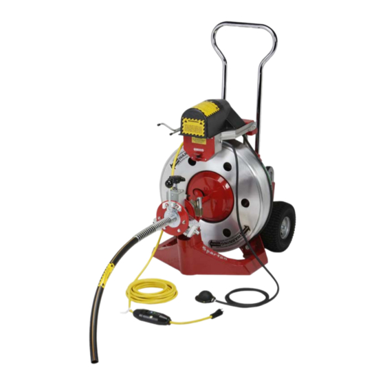
MODEL 2001
Owner's Manual
Spartan Tool L.L.C.
800.435.3866
www.spartantool.com
AN
AN
AN
AN
© 2012 Spartan Tool LLC
Advertisement
Table of Contents

Subscribe to Our Youtube Channel
Summary of Contents for Spartan Tool 2001
- Page 1 SP ART ART AN MODEL 2001 Owner’s Manual Record the Serial Number of your Model 2001 and give the number to the factory when ordering parts. Serial Number_________________________ Spartan Tool L.L.C. 800.435.3866 www.spartantool.com 44292100 6-20-12 © 2012 Spartan Tool LLC...
- Page 2 Warning — Read the safety and operating instructions before using any Spartan Tool product. Drain and sewer cleaning can be dangerous if proper procedures are not followed and appropriate safety gear is not utilized. — Before starting unit, be sure to wear personal protective equipment such as safety goggles or face shield and protective clothing such as gloves, coveralls or raincoat, rubber boots with metatarsal guards, and hearing protection.
-
Page 3: Table Of Contents
Setting Your Cable Size ----------------------- 54 Maintenance ........29-30 Universal Power Feed - 04221000 --------- 55 Unpacking Instructions ......31 Model 2001 Power Feed - 44224200 ------ 56 Power Feed Assembly - 04217500 --------- 57 PARTS SECTION Bearing Block Assy (Long) - 04224000 ---- 58 Power Unit - 44226000 ...... -
Page 4: Introduction
NOTE: Information in this manual is current at the time of printing. Spartan Tool reserves the right to make changes and improvements to its products at any time without notice or obligation. -
Page 5: Safety Instructions
Safety Instructions Use of any electrical equipment in a wet or damp environment can cause fatal shock if not properly guarded against by the operator. 1. Know Your Drain Cleaning Machine. Read this Operator’s Manual carefully. Learn the operation, applications and limitations of this machine. 2. - Page 6 Safety Instructions (cont.) 3. Extension Cords. DANGER- Improper use of an extension cord will cause death or severe injury. The GFCI on the machine’s power cord does not protect the operator from electrical shock along the extension cord. If an extension cord must be used, it must be of an approved, three-wire construction, equipped with a three-pronged plug, and in good condition.
- Page 7 Safety Instructions (cont.) 11. Dress properly. Do not wear loose clothing or jewelry. They can be caught in moving parts. Wear protective hair covering to contain long hair. Wear standard equipment. (Spartan riveted gloves). Never grasp a rotating cable with a cloth or loose fitting glove which would get wrapped around cable.
-
Page 8: Safety Instructions
Safety Instructions (cont.) 21. Maintain Tools with Care. Keep tools sharp and clean for better and safer performance. Follow instructions for lubricating and changing accessories. Never use damaged power cords. Inspect tool cords periodically and if damaged, repair with proper Spartan replacement parts. Inspect extension cords periodically and replace if damaged. -
Page 9: Description
Description GENERAL DESCRIPTION. The Spartan Model 2001 Electric Sewer and Drain Cleaner is designed for cleaning 3” to 10” sewer and drain lines up to 300’ long. The complete machine has five major components - the frame, cable drum, power drive unit with electric controls, “Dial-A-Cable” power feed, and removable smart-cart. - Page 10 Description (cont.) SPECIFICATIONS Drum Capacity ........3/4 inch 112 ft .66 magnum 137 ft Cleaning Capacity ...... 3” to 10” up to 300 ft Motor ... Permanent Magnet 120VAC 60Hz (Rectified) 4.2 amp (DC) max @ 200 inch - 02 Torque 180 RPM .36 HP 3000RPM @ 1 amp no load automatic brake Weight .....
- Page 11 CABLE ASSEMBLIES. The Model 2001 is designed to handle four types of cable assemblies listed in the Specifications Section of this manual. POWER CABLE FEED. The Spartan Dial-A-Cable power feed is standard on the Model 2001.
- Page 12 Description (cont.) SMART CART. An exclusive feature of the Model 2001 is the Smart Cart which can transport the complete machine or can be removed to handle loaded cable drums separately. A double shaft arrangement on the cart can be swung to carry the complete machine, or the cable drum, or power unit separately.
- Page 13 Description (cont.) FRAME Spring latch SHAFT engaged in lower DOUBLE SHAFT ASSEMBLY. The lock position. Double Shaft Assembly can be swung to carry the complete machine, the PIVOT cable drum, or power unit separately. SHAFT The Assembly has two engagement positions: upper and lower.
- Page 14 Description (cont.) TRANSPORTING COMPLETE MACHINE OR POWER UNIT. Starting with the Smart Cart unattached from the Machine/Power Unit, pull back the spring loaded latch handle to disengage the spring latch. Slide the spring loaded latch assembly up and engage the latch in the upper position.
-
Page 15: Before Operation
Before Operation WARNING: Operator must be thoroughly familiar with the Safety Instructions of this manual before attempting to operate this equipment. PREPLANNING OPERATIONS. Before starting a cleaning operation, preplanning will save time, money and effort. After analyzing the blockage problem; consider the type of cable and tools needed, determine best location for the machine and cable entry, and consider access to the power source. - Page 16 Before Operation (cont.) CABLE DRUM REPLACEMENT. Loaded cable drums can be quickly installed on the machine for added cable reach or to change cable size. Loaded or empty drums can also be removed from the power unit for replacement or for easier transport of machine and drum. NOTE: If the drum is loaded with cable, use the Smart Cart to transport it to the power unit.
- Page 17 Before Operation (cont.) DRUM INSTALLATION. Install the drum on the power unit as follows: 1. Check the drum anchor cable or supply cable extends a few inches from the ditributor arm so the female coupling is clear. If there is an expansion pin in the female coupling, drive it out before installing the drum.
-
Page 18: Before Operation
Before Operation (cont.) DIAL-A-CABLE POWER CABLE FEED. The Spartan Dial-A-Cable power feed unit provides infinitely variable cable penetration speeds. The single lever control varies the speed, and the forward or reverse movement of the cable through two lower and one upper bearing assemblies. The two lower bearing blocks can be adjusted to match the cable size in the drum. -
Page 19: Operation
Operation WARNING: Operator must be thoroughly familiar with the Safety Instructions section before attempting to operate this equipment. WARNING: Always use safety goggles. Guard against foreign material that might fly off the cable. BEFORE OPERATING CHECK LIST. Before starting operation, check the following: 1. - Page 20 Operation (cont.) WARNING: Avoid operating machine in reverse. Operating machine in reverse can result in cable damage and is used only to back stuck or imbedded tool out of an obstruction. Continual drum rotation in reverse position will cause cable to “jump” out of drum.
- Page 21 Operation (cont.) CLEANING OPERATION. Move the machine as close to the entry point as possible. The end of the cable safety guide and cutting tool should be inside the entry point of the cleanout. This machine should be operated from the side of the power feed. During operations, always have one hand on the power feed lever, and the other hand resting on the cable safety guide so torque build-up may be felt as the motor slows down.
- Page 22 Operation (cont.) Kinkage and breakage of cable are caused by allowing the working end of the cable to get hung up in an obstruction while twisting the other end with the motor, until something must give. The only way to clean an obstruction from a line, or negotiate a bend in a line, is with the blade rotating. A good rule to follow for releasing tension on a cable is: when the blade gets hung up in the obstruction and fails to rotate, a motor RPM sound reduction will be noticeable, which indicates it is time to pull the blade away from the obstruction.
-
Page 23: Operation
Operation (cont.) CABLE PULLBACK. When the job is complete, feed the cable back into drum by moving the power feed lever towards the “R” position, making sure the machine is running forward with the power switch in “FWD” position, so that the distributor arm can feed and distribute cable into the drum properly. -
Page 24: Cable And Tools
Cable and Tools CABLE DESCRIPTION. There are two types and sizes of cable available for the Spartan 2001. Each is designed for particular types of cleaning operations. Consult your Spartan Tool Representative for the cable type to be used in each applications. - Page 25 SPARE DRUMS. Due to the ease of changing cable drums on the Model 2001, it may expedite the job to have spare drums already loaded with the cable to be used on the job. When cleaning further than the length of cable available in the drum, and change drums, refer to the procedure for cleaning farther than 100’...
- Page 26 Cable and Tools (cont.) BLADE ASSEMBLY. Blade assembly and attachment to the cable is the same for both types of blades. Either a double male coupling or a 2’ leader cable is used to attach the cutters. 1. Seat the blade holder assembly on the leader or male coupling threaded end. 2.
-
Page 27: Cable And Tools
Cable and Tools (cont.) REMOVING ANCHOR CABLE Remove drum from the machine. Pull anchor cable out through the distributor arm as far as possible. Using external retaining ring pliers, remove external retaining ring from inner drum shaft at rear of the drum. With distributor arm and cable at the notch in the drum opening, pull the inner drum away from the outer drum exposing the anchor clamp at the end of the anchor cable Loosen the two cable clamp screws from rear outside of the drum. -
Page 28: Special Applications
Special Applications CAUTION: Excessive distance between the drain/sewer cleaning machine and pipe opening may cause rotating cable to become uncontrollable and lead to personal injury. CLEANING FARTHER THAN DRUM CAPACITY. Cable can be added to the operation in two ways - replacing a loaded drum on the machine, or reloading cable into the cable drum. To replace the drum, refer to DRUM ASSEMBLY HANDLING in BEFORE OPERATION Section of this manual. -
Page 29: Maintenance
NOTE: If any maintenance is required other than listed above or any other problem, call your Spartan Tool Territory Manager or contact Spartan Tool. Refer to your Spartan accessories book or parts manual for all repair parts and machine options. - Page 30 Maintenance (cont.) CHECK LIST FOR MACHINE MAINTENANCE Electrical power cable Inspect for damaged cord, ground fault interrupter and plug connections, 3-prong plug. Ground fault interrupter Test breaker for correct operation using test button. Foot actuator Test operation of foot actuator to be sure motor does not operate unless actuator is pressed.
-
Page 31: Unpacking Instructions
Unpacking Instructions UNPACKING AND ASSEMBLY. The power unit carton will include the power unit with drum and cable safety guide. Before unpacking the cartons, examine them for damage that might have occurred during shipping. In case of damage, report it immediately to the carrier. Unpack the power unit and drum from the carton and examine them for damage also. -
Page 32: Parts Section Power Unit - 44226000
44225300 Assy Cable Guide 44228500 Assy, Cable Retriever 71108000 Machine ID Plate 44292100 Manual, 2001 Owners 44281400 Decal, 1065, 300, 2001 Safety 44163000 Safety Instructions 44291500 Adapter, Anchor .66 - 3/4 02769100 Bearing, Thrust 44239700 Spacer, Steel 1.505" ID x 2.379"... -
Page 33: Frame Assembly - 44213200
44226600 Assy, Locking Pin 02825000 W asher, Lock 5/16 00167100 Internal Tooth Lockwasher 44213300 Assy, Upper Back 44294000 Assy, 220V PM Mtr Support 2001 44291000 Assy, PM Motor Support 44216600 Smart Cart Assembly 44220000 Propeller Tee Nut 5/16-18 Additional Parts - see page 32... -
Page 34: Upper Front Assembly - 44212900
Upper Front Assembly 44212900 ITEM QTY P ART NUMBER DESCRIPTION 44212400 2001 S wing B olt 03424000 Assy, Handle B ody 44213000 Pin, Roll P in 1/4 x 1.50 Locking Pin Assembly 44226600 ITEM QTY PART NUMBER DESCRIPTION 44225200 Pin, Quick Release 77726800 Chain, #5 Double Loop .062"... -
Page 35: Smart Cart Assembly - 44216600
Smart Cart Assembly 44216600 26 27 24 13 14 19 18 20 18 16 DESCRIPTION DESCRIPTION PART NO. PART NO. ITEM QTY ITEM QTY SMART CART-MACHINED CAP, PROTECTIVE 44215000 44217600 ASSY, LOCK DOUBLE SHAFT ROLL PIN, 1/8 X 1 44300000 44217400 BLOCK, PIVOT ROD, KICK STAND... -
Page 36: Double Shaft Assembly - 44300000
Locking Double Shaft Assembly 44300000 ITEM QTY PART NO. DESCRIPTION 44301000 WELDMENT, LOCKING DOUBLE SHAFT 44217100 ROLL PIN .25 X 3.00 44216300 SHAFT, PIVOT 44225700 SPACER, NYLON 02893300 SCREW, SOC HD SET 1/4-20 x 5/16 44218200 CAP, 1" PLUG 44300100 WELDMENT, DOUBLE SHAFT LOCK 44300800 LATCH, SMART CART DOUBLE SHAFT 44300350 SPRING, EXTENTION 44300400 FOAM GRIP 3/16-1/4 X 1-1/2... -
Page 37: Motor Support Assembly - 44291000
Item Q ty Q ty Numbe r De scription 44210200 Cas ting, Motor Support Mac hined 2001 44290000 PM Motor Ass y w/ Brake 44002600 Pressure Switc h 71107600 Velcro 71103300 Power Cord w / GFI 44225800 As sy, Air Footswitc h w / Sleeve... -
Page 38: Wiring Diagram
Outlet Cover Assembly 44290900 P a rt Ite m Qty Num be r De scription 44290901 Cover, Outlet Box 2001 44221500 Toggle Switch Assy 04714900 Label, Switch Direction 44230200 Guard, Toggle Switch 44290400 Label, W arning S top Motor Page 38... -
Page 39: Drum Assembly - 44219505
Drum Assembly 44219505 Item No Qty Part No. Description 44214000 Assy, External Drum 44214100 Assy, InnerDrum 02822500 Retaining Ring 44292400 .66 Universal Anchor Assy. 44218400 Assy, Bearing Support 02751600 Set Collar Assy .66 Universal Anchor Assembly 44292400 ITEM QTY PART NUMBER DESCRIPTION 02821800 Expansion Pin 3/4"... -
Page 40: External Drum Assembly - 44214000
44218800 Assy, Hub 00167100 Internal Tooth Lockwasher 00165600 Washer Lock - Split Medium 02885000 Cable Clamp Assy. 02796300 Grease Zerk 1/8" 45 Deg. 44219300 Label, Drum 2001 44230000 Plub, Button 1/2" 00115100 Screw, Hex Hd Cap Inner Drum Assembly 44214100 Item Req'd Part No. -
Page 41: Motor Assembly - 44290000
Motor Assembly 44290000 Pa rt Num be r Re q'd De scription 44304000 M otor A s s em bly Brus h K it Air Foot Switch - 44225800 Ite m No Pa rt No Re q'd De scription 44055500 Air Foot Switch (Complete As Shown) 04576900 Pressure Transmitter... -
Page 42: Decal Package - 44230600
Decal Package 44230600 Pa rt Ite m Qty Num be r 44228800 44228700 44219300 04220000 44228900 44290400 44219400 44229000 04714900 Page 42... - Page 43 Decal Package (cont.) 44230600 Page 43...
-
Page 44: 3/4" Cable For 2001
3/4” Cable for 2001 Spartan 3/4” Cable With and Without Inner-Core for Use in 3” to 10” Lines 3/4" No Tens ion 3/4" Sew er Inner-Core Cable w /o Inner- (Loos e Wound 3/4" Inner-Core Core f or "P" Traps) Dia - Lth P a rt No. -
Page 45: .66 Magnum Cable For 2001
.66 Magnum Cable for 2001 Spartan .66 Magnum Cable for Use in 3” to 10” Lines Dia - Lth Part No. Item .66 x 25' 44053505 Part No. Description .66 x 50' 44053502 44120500 Female Coupling .66 x 10' 44053501 44053400 Splicer .66 x 2'... -
Page 46: Compact Lift - 02884900
Compact Lift - Optional 02884900 Item Part No Req'd Description 02888700 Rail & Hook Assembly 02888500 Spring 02811900 Wheel, Model 100/200 02821800 Pin, Roll 1/4 Dia X 3/4 03410500 Adjustable Knob 02887600 Locating Pin 02826200 Screw, Hex Hd 5/8-18 x 3 02821300 Stop Nut 5/8-18 00760400... -
Page 47: Tool Box And Accessory Kit
Tool Box and Accessory Kit 44060700 (.66 Cable) - 04647000 (3/4 Cable) Item Req'd Part No. Description 44060700 Tool Box & Assy Kit (.66) 04647000 Tool Box & Assy Kit (3/4") 02752500 Tool Box 02883200 Cable Uncoupling Stand 02807700 Retriever 02893900 Glove (Pair) 02799400... - Page 48 Tool Box and Accessory Kit (cont) Item Req'd Part No. Description 02799100 3" "P" Trap Blade 02799200 3-1/2" "P" Trap Blade 02798700 4" Saw Blade 02799600 2" - 3 Blade Cutter 02791700 3" - 3 Blade Cutter 02791800 4" - 3 Blade Cutter 02870300 6"...
-
Page 49: Spartan Accessory Blades
Spartan Accessory Blades Page 49... -
Page 50: Power Cable Feed Section
MODEL 75 Power Cable Feed Section Operating & Maintenance Instructions Page 50... - Page 51 Attaching the Cable Safety Guide ----------- 53 Setting Your Cable Size ----------------------- 54 Universal Power Feed - 04221000 --------- 55 Model 2001 Power Feed - 44224200 ------ 56 Power Feed Assembly - 04217500 --------- 57 Bearing Block Assy (Long) - 04224000 ---- 58...
-
Page 52: Introduction
10 pounds, will feed and retrieve a cable up to 30 feet per minute. A universal mounting plate allows adaptation to current Spartan Model 1065’s, 200’s, 300’s, and 100’s. (The Model 2001 does not need a mounting plate.) The power cable feed can be used on cable size from 5/16” through 3/4”. -
Page 53: Attaching The Cable Safety Guide
Attaching the Cable Safety Guide To The Power Cable Feed Disconnect the cable machine from its power source to avoid accidental starting. Pick up the Cable Safety Guide and place the spring against the hub on the Power Cable Feed and turn it counterclockwise until the spring rests against the plate behind the hub. -
Page 54: Setting Your Cable Size
Setting Your Spartan Power Cable Feed for Cable Size (Refer to Fig. 2 for details) Fig. 2 To adjust for cable size, push in on the pin knob (#37) located on the bottom of the bearing blocks (#29) to unlock from setting. Turn pin knob right/clockwise and pull out. As each cable setting is reached the knob can be felt locking in. -
Page 55: Universal Power Feed - 04221000
Model 75 Universal Power Feed 04221000 (Universal Unit Fits 100-200-300-1065 Machines) Reference: FIG 4 Item # 11 For use with model 300 only Fig. 14 PART ITEM NUMBER DESCRIPTION 03409000 Bushing Lock 00113600 Screw, Hex Hd 1/4-20 x 3/4 00162400 Washer, Flat 3/16 USS 00167000 Lockwasher, Internal Tooth... -
Page 56: Model 2001 Power Feed 44224200
Model 2001 Power Feed 44224200 Fig. 15 PART ITEM QTY NUMBER DESCRIPTION 02856900 KNOB 04134900 NUT ACORN CAP 5/16-18 04220000 DECAL BRG PLATE MOD 75 FEED 44224100 BEARING PLATE 00162600 WASHER, FLAT 5/16 USS 44223900 2001 ACTURATOR ASSY 04218300 PLATE STATIONARY 75 FEED... -
Page 57: Power Feed Assembly 04217500
04134900 NUT ACORN CAP 5/16-18 04220000 DECAL BRG PLATE MOD 75 FEED 44224100 BEARING PLATE 00162600 WASHER, FLAT 5/16 USS 44223900 2001 ACTURATOR ASSY 04218300 PLATE STATIONARY 75 FEED 00167100 INTERNAL TOOTH LOCKWASHER 00169500 SCREW, HEX HD CAP 5/16-18x3-1/2 44249900 MOUNTING PLATE, MODEL 300/1065... -
Page 58: Bearing Block Assy (Long) 04224000
03312001 Nut Kep #8-32 Zinc Plated 44221900 2001 Cover Spring 01921801 Screw, Mach Rd Hd Sl 8-32 x 1/2 44230100 2001 Spring Feed Ext 03415800 Knob and Screw Assy 04219000 Cap End Weld Assy 75 00113700 Screw, Hex Hd 1/4-20 X 3/4... -
Page 59: Bearing Block Assy (Short) 44219900
04217800 Block Bearing Short Mod 75 Feed 00113901 Screw, Hex Hd 1/4-20 x 1 04219600 Thrust Race 04219500 Thrust Bearing 44222100 2001 Knob 44213800 Dial A Cable Block 44222200 Roll Pin 2001 FIG 8 44119700 Wheel Carrier Body Comp (Short) Page 59... -
Page 60: Wheel Carrier Body (Long) - 44119600
Wheel Carrier Body Comp (Long) 44119600 PART ITEM QTY NUMBER DESCRIPTION 04217700 Pin Drive Mod 75 Feed 04219700 Bearing Drive Mod 75 Feed 04219800 Washer 75 Feed Stainless 04219900 Ring Retaining-External 44250200 O-Ring Seal, Wheel Carrier 04218400 Body Wheel Carrier w/ Hole Long (Includes item 30) Fig. -
Page 61: Model 1065 & 2001 Installation
8. Apply grease through grease fitting on bearing assembly. Installation is complete. Refer to operating instructions for safe operation. Special Note: 2001 Dial-A-Cable Power Feed Replacement. When Replacing Dial-A-Cable power feed unit on 2001 machines, the two (2) long screws #15 must be used for old unit. Page 61... -
Page 62: Model 200 And 300 Installation
Installation Instructions For Model 300 (See: Fig. 4, Fig. 5 & Fig 14) Fig. 9 The following instructions are for manual machines, delete step 1 through 3 when replacing older power feed units. 1. Remove upper front casting assembly. 2. Install new upper front casting assembly (04202700). 3. -
Page 63: Model 100 Installation
Installation Instructions For Model 100 (See: Fig. 4 and Fig. 5) The following instructions are for manual machines, delete step 1 through 3 when replacing older power feed units. 1. Remove mounting plate (#16) from Dial-A-Cable power feed and reposition bolts in upper holes in (#16) plate. -
Page 64: Operating Instructions
Operating Instructions For Model 75 Dial-A-Cable Power Feed (See: Fig. 4, Fig. 5, Fig. 6 & Fig. 8) Follow all safety instructions as outlined in your operator’s manual supplied WARNING! with your machine. If a new operator manual is required, contact Spartan Tool (800-435-3866) or download it at www.spartantool.com. -
Page 65: Cleaning Operation
1. Remove top two (2) acorn nuts #3 from screws #15 that holds feed unit to mounting plate #16. (On 2001 unit, remove two (2) #15 screws at bottom that holds feed unit to upper front casting). 2. Remove feed unit from mounting screw #15 by pulling forward. -
Page 66: Disassembly Of Short Bearing Blocks
Disassembly of Short Bearing Blocks (See: Fig.10 and Fig. 11) 1. Pull wheel carrier bodies #21 from blocks #29. 2. Remove the two (2) thrust races #33 and one (1) thrust bearing #34 from each unit. 3. Remove four screws #31 holding Dial-A-Cable assembly #35, 36, and 37 to bearing block #29. (Do not disassemble unit) 4. -
Page 67: Disassembly Of Long Bearing Blocks
Disassembly of Long Bearing Blocks (See: Fig.12 and Fig. 13) 1. Remove the two (2) screws #20 holding spring cover #7 to top of long bearing block #23. Leave remaining two (2) screws. 2. Pull wheel carrier body #32 from block #23 with cove #7 and spring #9 attached. 3. -
Page 68: Cleaning & Lubricating Instructions
Cleaning and Lubricating Instructions WARNING! The cleaning of parts in this instruction section recommends the use of kerosene for parts cleaning which is combustible and care should be used. Always work in a well ventilated area away from fire or open flame. When parts cleaning, always wear eye protection, rubber gloves and plastic or rubber apron. -
Page 69: Re-Assembly Of Long Bearing Blocks
Re-Assembly - Long Bearing Blocks 1. Replace “O” rings #30 into groove in long wheel carrier block #32. (Spring hole in bottom) 2. Lubricate inside cylindrical section of long bearing block #23. Install end cap #19 on end of long bearing block with two (2) short screws #20. -
Page 70: Cable Safety Guide Instructions
Cable Safety Guide Instructions The Spartan Tool Cable Safety Guide has been designed to improve the operational safety. It’s purpose is to prevent direct contact with the rotating cable. To install, place the spring end of the Cable Safety Guide against the hub of the power feed and rotate it counterclockwise under pres- sure until the spring rests against the wall of the Actuator Assembly. -
Page 71: Cable Safety Guide Instructions
Cable Safety Guide Instructions (cont) The length of the Cable Safety Guide is the correct distance the machine should be located from the pipe opening. If the machine cannot be located as prescribed, precautions must be taken. A pipe section must be placed in the area between the “cleanout entry” and the end of the Cable Safety Guide to avoid injury. - Page 72 EC Declaration of Conformity Page 72...
-
Page 73: Warranty Information
Spartan Tool will direct where to take or send the equipment for service. If the defect is covered by the warranty, Spartan Tool will repair or replace, at its option, the defective equipment, without charge for labor or materials. (Freight and insurance are the purchaser’s responsibility.)
Need help?
Do you have a question about the 2001 and is the answer not in the manual?
Questions and answers